Overview
The Challenger 350 aircraft is an all metal, pressurized, low-wing, turbofan-powered monoplane. The wing design is a high-aspect ratio, fully cantilevered, swept-back wings with winglets. The fuselage is of semi-monocoque construction and uses a constant circular cross-sectional shape fuselage.
The aircraft structure is primarily fabricated from aluminum alloys but also includes alloy steels, stainless steel, titanium, and composites.
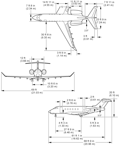
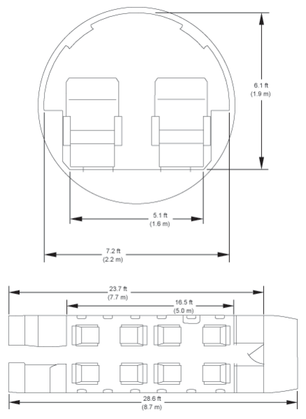
Dimensions and Areas
The aircraft exterior and interior dimensions are illustrated.
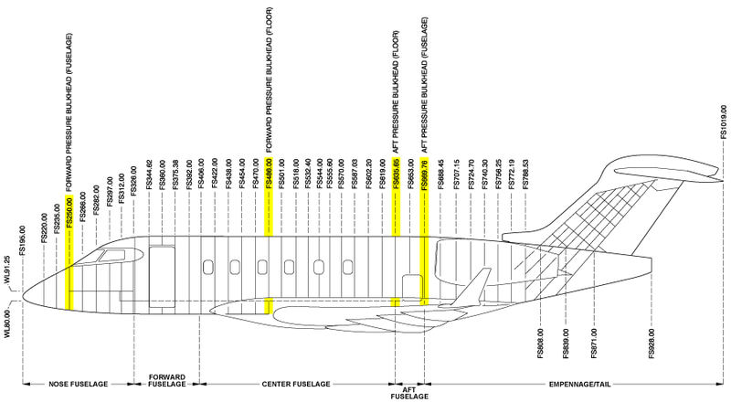
Fuselage Stations
The Fuselage Stations (FS) are measured along the longitudinal axis of the aircraft and are reference planes found at right angles to the fuselage center line. The primary FS datum line (FS0.00, not shown) is 195.00 inches forward of the aircraft nose (FS195.00). The aircraft is divided into the primary fuselage areas that follow:
- Nose fuselage area
- Forward fuselage area
- Center fuselage area
- Aft fuselage area
- Empennage and tail area
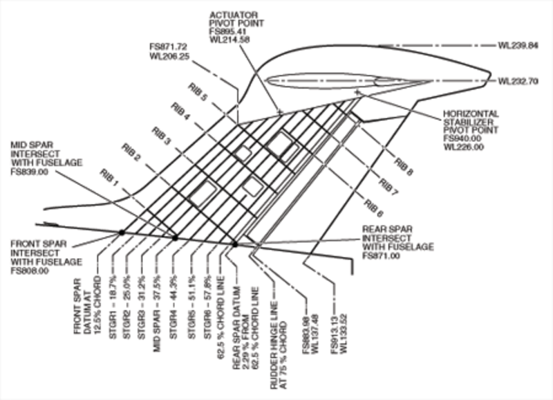
Vertical and Rudder Stations
The vertical stabilizer ribs also have references to the percentage (%) of chord line. The 0% chord point is the point at the leading edge of the vertical stabilizer where a vertical line intersects with the fuselage. The 100% chord point is the point at the trailing edge of the rudder where a vertical line intersects with the fuselage. The percentage of chord numbers shown in the figure are related to the range between the 0% chord and 100% chord points.
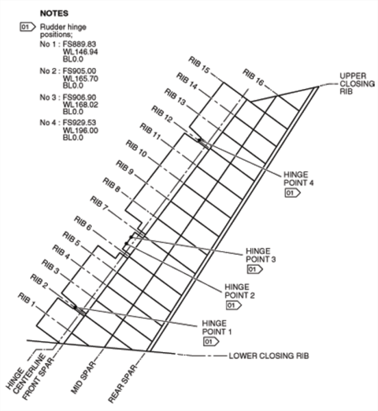
For the rudder, the ribs are found at right angles to the rear spar. The rudder spar center line is parallel to the rear spar of the vertical stabilizer. The rudder has four hinge positions.
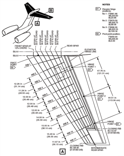
Horizontal Stabilizer and Elevator Stations
The horizontal stabilizer and the elevator are identified by their ribs, closing ribs, spars, horn spars and stringers.
For the horizontal stabilizer, the ribs are found at right angles to the rear spar and intersect the stringers, the front and the rear spar. The horizontal stabilizer has one pivot point and three hinge points.
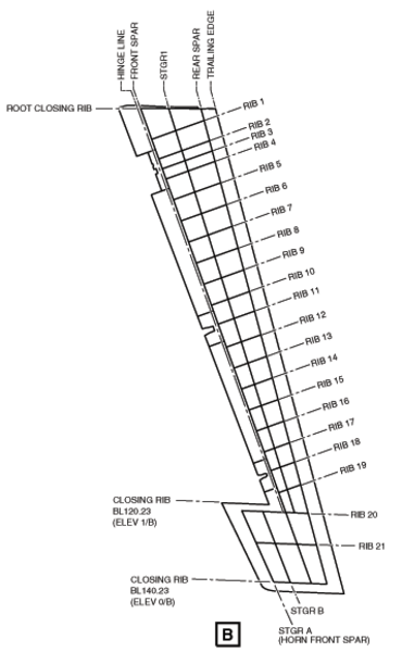
For the elevator, ribs 1 to 19 are found at right angles to the front spar. Ribs 20 and 21 intersect the horn front spar at an angle other than the right angle. The elevator hinge line is parallel to the front spar of the elevator. The elevator has three hinge positions.
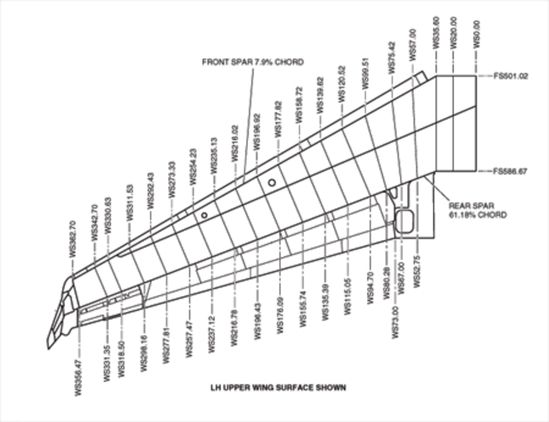
Wing Stations
The wing stations (WS) are measured along the lateral axis of the aircraft. The WGLTS abbreviation is used to identify winglet stations.
The wings have references to the percentage (%) of chord. The 0% chord line is the line made by the leading edge of the wings. The 100% chord line is the line made by the trailing edge of the flaps and the ailerons of the wings. The percentage of chord numbers shown in the figure are related to the range between the 0% chord and 100% chord lines.
The length of the wing chord changes from the wing root to the wing tip. This is because the 0% and the 100% chord lines are not parallel.
The primary WS datum line (WS0.00) is 370 inches inboard of the wingtip (WS370.00). The WS datum point is at the fuselage center line which divides the center wing.
The WRP is the horizontal datum line that goes through the wing's aerodynamic center line. The WRP is at a right angle to the WS.
The WGLTS also have references to the percentage (%) of chord. The 0% chord line is the line made by the leading edge of the WGLTS. The 100% chord line is the line made by the trailing edge of the WGLTS. The percentage of chord numbers shown in the figure are related to the range between the 0% chord and 100% chord lines.