


Overview
The integrated flight information system (IFIS) is a multi-function display (MFD) upgrade that adds electronic charts (e-charts), graphical weather (GWX), and enhanced map (e-map) features to the existing electronic flight instrumentation system (EFIS).
The IFIS is made up of one or two (optional) file server units (FSU), two cursor control panels (CCP), and two MFDs (with ethernet capability). A third VHF COM transceiver with datalink and a radio interface unit (RIU) with an integral communication management unit (CMU) are required when the optional Universal weather (GWX-5000) is installed. An XM weather receiver is required when the optional XM weather (GWX-3000) is installed.
The primary system component is the FSU. The CCPs are part of the EFIS, and allow a dedicated interface to the MFD for controlling the IFIS functions via on-screen menus. The VHF datalink radio and RIU provide air and ground data communications with compatible air-ground networks when the optional universal weather is installed. A control display unit (CDU) requests universal weather from the ground-based service provider and displays IFIS messages. The optional XM weather receiver receives a constant broadcast of graphical and textual weather data from the XM satellite radio weather service provider. The XM satellite provides weather data to the FSU through the XM weather antenna and the XM weather receiver.
01/16/16
File Server Unit
The FSU supplies stored graphical symbology to the MFDs through a dedicated bi-directional ethernet bus. The FSU contains large data bases using non-volatile random access memory (NVRAM). In a dual FSU installation, each FSU is connected to the respective on-side MFD only. A second optional FSU is available for installation.
The key operating features for the FSU are as follows:
- E-charts available for display on the MFD
- Automated e-chart selection linked with FMS flight plan
- GWX available for display on the MFD (for example: plan map)
- E-map (geographical/political, airways, airspace) available for display on the FMS PPOS map and FMS plan map
- System status pages are available for display on the MFD
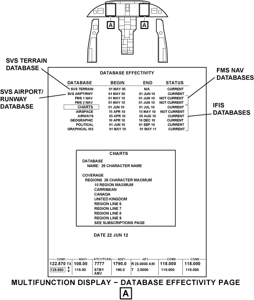
The FSU also provides a gateway service for upload and download of data to other LRUs on the aircraft using Rockwell Collins portable access software (CPAS-3000). A data base subscription or data service is required for each of the features of IFIS. There are data bases associated with each of the IFIS features that require periodic updates. The FSU contains the following data bases with the update cycle:
- Charts (14 day update cycle)
- Airspace (28 day update cycle)
- Airways (28 day update cycle)
- Political (update on user demand)
- Geographical (update on user demand)
- Graphical weather (XM and UV) (update on user demand)
When an installed data base is out of date, the CHECK DATABASE STATUS message shows on the MFD. The DATABASE EFFECTIVITY pages shows the flight crew or maintenance personnel the status of the installed data base.


Electronic Charts
The electronics charts (ECH-5000) function provides the display of arrival procedure (STAR), approach procedure, airport diagram, departure procedure (SID or DP), noise and notice-to-airmen (NOTAM) charts on the MFD. Access to the e-charts format is through CCP CHART pushbutton. With the FMS installed, the origin, departure, and alternate airports and procedures are automatically filled in from the flight plan data to provide easy access to all charts pertinent to the flight plan. Pilot entered stations IDS are also supported. The e-chart function also depicts the aircraft position on all geo-referenced charts.
Chart files are updated (on a subscription basis with Jeppesen) on a periodic basis. The chart database is dataloaded into the FSU.
Split Charts
The split chart function provides the display of two charts. The split chart view provides a profile and minimum strip views. In the split chart view while in flight, when the TOGA pushbutton is pushed, the view defaults to the briefing strip view. The DSK DATA control knob on the CCP controls the display for the split charts.
Automatic Charts
The automatic charts function provides an automatic chart display on the MFD. When the aircraft is in an on ground status, the chart of the destination airport is shown on the display.

Enhanced Map Overlay (Post SB 350-46-004)
The enhanced map overlay (OVL-5000) function provides the display of individual symbology of geopolitical boundaries (state and country boundaries, major water), airways (high and low), and restricted airspace on the MFD present position and plan maps.
The enhanced map overlays provide the functions that follow:
- NEXRAD (from GWX-300X or GWX-5000)
- Airways (Victor and Jet)
- Airspace (class B and class C terminal airspace and restricted airspace)
- TFRs (from the GWX-300X)
Universal Graphical Weather (Post SB 350-46-003)
Universal weather (GWX-5000) is requested for uplink through the CDU. The graphical weather images are uplinked to the aircraft through the VHF No. 3 (option) system. The graphical weather images are displayed on the MFD. The MFD format displays one stored graphical weather at a given time. The images received are stored in the FSU and are automatically listed in the graphical weather image menu. The graphical weather menu provides effectivity information and timestamp information of the various images and forecast products. Images that are no longer valid are automatically deleted from the FSU when the aircraft is on the ground.
The universal weather images are provided as follows:
- NEXRAD radar images (CONUS)
- Tops and movement (CONUS)
- Weather depiction (ceiling and visibility summary) (Worldwide)
- Icing (at forecast times) (Worldwide)
- Turbulence (at altitudes) (at forecast times) (Worldwide)
Note:
Only one service, either XM weather or universal weather, may be installed on an FSU at one time.
In a dual FSU installation, the uplinked images are cross-talked between the units to avoid the cost of requesting the images on both sides.
Radio Interface Unit
The radio interface unit (RIU) is required for installations that include the universal weather (GWX-5000). Graphical weather images are requested from the ground station through control pages on the CDU. The requested GWX images are uplinked through the VHF COM No. 3 (option) unit and supplied to the FSU through the RIU.

XM Weather (Post SB 350-46-002)
XM weather (GWX-300X) is enabled by an electronic key. The function provides capability to show and use the graphical and textual weather information for the CONUS USA, Canada, and Puerto Rico.
XM Weather CONUS USA
The XM weather CONUS USA provides the functions that follow:
- High-resolution animated NEXRAD imaging overlay
- Origin and destination ICAO shown on the overlay
- Severe weather storm track (storm cell identification tracking (SCIT)
- Textual TAF and METAR reports for station IDs
- Textual SIGMET and AIRMET reports
- METAR overlay
- SIGMET overlay
- Lightning strike overlay
- Satellite imagery
- Winds aloft
- Icing level
- Turbulence
- Temporary flight restrictions (TFRs) shown on the map
XM Weather Canada
The XM weather Canada provides the functions that follow:
- Radar coverage
- High resolution NEXRAD radar
- Winds aloft
- METARS
- TAFS
- Textual AIRMETs and SIGMETs
XM Weather Puerto Rico
The XM weather Puerto Rico provides the functions that follow:
- Radar coverage
- High resolution NEXRAD radar
- Surface precipitation
- Sever weather storm track
- TFRs
01/16/16
File Server Unit Mounting Tray
The file server unit mounting tray is a mounting tray that holds the file server unit in the equipment rack. The FSU mounting tray is attached to the equipment rack with screws.
There is one FSU mounting tray for the FSU No. 1 and one FSU mounting tray for the optional FSU No. 2.
Each mounting tray has a hold-down clamp that engages in the hold-down hook of the FSU.
The FSU mounting tray has an integral cooling fan. The cooling fan receives 28 VDC power input. The cooling fan outputs the FAN MONITOR discrete to the FSU. The FAN MONITOR discrete indicates the fan speed to the FSU.

01/16/16
External Compensation Unit
The external compensation unit (ECU) is remotely mounted.
The ECU is a personality module that stores the FSU configuration information and the encrypted application keys (EAK). The EAK is an alphanumeric string that is generated to unlock an application on the single aircraft for which the EAK is generated to. An EAK for one aircraft does not work for another aircraft. The EAKs enable and disable features of the FSU. Each FSU (FSU No. 2 if installed) has a dedicated ECU as part of the system. The ECU has two electrically erasable programmable read-only memory (EEPROM) chips that store the FSU configuration data.

01/16/16
XM Weather Receiver (Post SB 350-46-002)
The XM weather receiver receives a satellite signal from the XM WX aviation weather service provider.
The XM weather receiver receives streamed data and sends the data to the FSU. The data stream includes the products that follow:
- High-resolution animated NEXRAD imaging overlay
- Origin and destination ICAO shown on the overlay
- Sever weather storm track (storm cell identification tracking (SCIT))
- Textual TAF and METAR reports for station IDs
- Textual SIGMET and AIRMET reports
- METAR overlay
- SIGMET overlay
- Lightning strike overlay
- Satellite imagery
- Winds aloft
- Icing level
- Turbulence
- Temporary flight restrictions (TFRs) shown on the map
The XM weather receiver and antenna hardware are provided by Rockwell Collins. The XM weather subscription service is provided by XM WX Satellite Weather. Call 1-800-985-9200 for service provider specific questions.
Note:
Only one service, either XM WX aviation weather or universal weather, may be installed on an FSU at one time.

01/16/16
XM Weather Antenna (Post SB 350-46-002)
The XM weather antenna receives a satellite signal from the XM weather service provider. The XM weather antenna is located on top of the aircraft (FS538.00) and is mounted to the aircraft surface. The aircraft must be in line-of-sight of the XM satellite to provide a continuous signal.

01/16/16
System Operation
File Server Unit 1
The FSU uses NVRAM solid state memory to function with the mass media storage. The FSU provides a gateway service for the upload and download of data to other LRUs on the aircraft. The USB port on the DBU-5010E with an ethernet connection provides the dataload function.
The FSU has four ethernet channels. Three of the four channels are capable of 10/100 Base-T ethernet communications. The fourth channel supports only 10 Base-T ethernet communications.
The FSU No. 1 outputs one ARINC 429 high-speed bus. The FSU No. 1 outputs the L-FSU-1 bus to the IOC No. 1 in the integrated avionics processing system (IAPS). The FSU No. 1 receives an input signal on the L-IOC-2 bus from the IAPS.
The L-FSU-3 bus provides the ARINC 429 software dataload capability (optional) for data load function.
The FSU No. 1 receives two ARINC 429 high-speed buses. The IOC No. 1 outputs the L-IOC-2 bus to the FSU. The L-IOC-2 bus contains the IAPS data.
The FSU No. 1 has three full-duplex RS-422 serial interfaces. The FSU No. 1 uses the RS-422 interface to load the monthly data base updates to the flight management computers (FMC) and new diagnostic tables to the maintenance diagnostic computer (MDC).
The FSU No. 1 outputs the L-FSU-21 (RSS-422) data load bus to the FMC No. 1. The FSU No. 1 outputs the L-FSU-22 (RSS-422) data load bus to the FMC No. 2. The FSU No. 1 outputs the L-FSU-23 (RSS-422) data load bus to the MDC. The FSU No. 1 receives an input from the L-FMC-5 (RSS-422) bus and from the R-FMC-5 (RSS-422) bus from the DBU and the IAPS. The MDC outputs the MDC-6 (RSS-422) data load bus to the FSU No. 1. The MDC-6 bus contains the data load status information from the MDC.
The FSU No. 1 outputs the L-FSU-11 ARINC 664 ethernet bus to the MFD. The FSU No. 1 supplies the electronic charts, enhanced map overlays that include geopolitical boundaries, lakes, rivers, and oceans, high and low level airways, restricted and controlled airspace, and obstacles, and graphical weather displays to the MFD No. 1. The data is formatted for display on the MFD without additional processing.
The MFD outputs the L-MFD-11 ARINC 664 ethernet bus to the FSU No. 1.
The FSU No. 1 outputs the L-FSU-12 ARINC 664 ethernet bus to the optional FSU No. 2.
The FSU No. 1 outputs the L-FSU-13 ARINC 664 ethernet bus to the ethernet connection to the DBU. The DBU outputs the DBU-13 ARINC 664 ethernet bus to the FSU.
The FSU No. 1 receives broadcast XM Weather data (option) through the XMWR-1 bus. This gives the current XM graphical weather display data for the IFIS.
File Server Unit 2 (Post SB 350-46-001)
The hardware and power description of the FSU No. 2 are the same as FSU No. 1. The SDI pins are grounded to indicate the FSU No. 2.
The FSU No. 2 receives ARINC 429 high-speed buses. The IOC No. 2 outputs the R-IOC-2 bus to the FSU. The R-IOC-2 bus contains the IAPS data. The RIU No. 1 outputs the L-RIU-12 bus to the FSU.
The FSU No. 2 has ethernet connections to the MFD and the DBU. The FSU No. 2 outputs the R-FSU-11 ARINC 664 ethernet bus to the MFD No. 2. The FSU No. 2 supplies the electronic charts, enhanced map overlays that include geopolitical boundaries, lakes rivers, and oceans, high and low level airways, restricted and controlled airspace, and obstacles, and graphical weather displays to the MFD No. 2. The data is formatted for display on the MFD without additional processing.
The FSU No. 2 outputs one ARINC 429 high-speed data bus through the R-FSU-12 ARINC 664 ethernet bus to the FSU No. 1.
The FSU No. 2 outputs the R-FSU-2 664 ethernet bus to the FSU No. 1. The FSU No. 2 outputs the R-FSU-13 ARINC 664 ethernet connection to the data base unit (DBU). The DBU connection outputs through the DBU-15 ARINC 664 ethernet bus to the FSU.
The FSU No. 2 receives broadcast XM weather data through the XMWR-1 bus. The signal gives the current XM graphical weather display data for the IFIS.
External Compensation Unit
The ECU has two electrically erasable programmable read only memory (EEPROM) chips that store the FSU configuration data. The CHIP SEL discrete outputs select the desired EEPROM to read or write data. The WRITE PROTECT discretes are grounded to write data to the selected EEPROM. The CLOCK line is used to clock data on the SERIAL DATA TX and SERIAL DATA RX lines.
The FSU supplies the ECU with 8 VDC power. The FSU has the SLOT STRAP and SDI strap inputs. The SDI pins are grounded to indicate the FSU No. 1.
XM Weather Receiver (Post SB 350-46-002)
Broadcast graphical weather for the IFIS is received by the XM weather antenna and processed by the XM weather receiver.
The FSU No. 1 and the FSU No. 2 receives broadcast XM weather data (option) through the XMWR-1 bus. This gives the current XM graphical weather display data for the IFIS.
XM Weather Antenna (Post SB 350-46-002)
The XM weather antenna is connected to the XM weather receiver. The XM weather antenna is located on top of the aircraft (FS538.00).
GWX-5000 Universal Weather (Post SB 350-46-003)
The VHF COM No. 3 receives datalink communication from the universal weather service provider. The signal is routed through the RIU to the FSU.
01/16/16
Control and Displays
The pilot and copilot have the ability to control the IFIS features with the CCP No. 1 and the CCP No. 2. The CDU No. 1 and the CDU No. 2 are also used to control the GWX-5000 images and menu.
Cursor Control Panel
The CCPs provide the display control inputs for the on-side MFD. The joystick positions the pilot-created waypoint on the FMS PPOS map, controls the view angle of the 3-D map, and does paging and scrolling through checklists. The CCP buttons select the engine indicating and crew alerting system (EICAS) page displays, the MFD format, checklist control, and optional 3-D map functions. The CCP controls and pushbuttons let the pilot and copilot pan and zoom charts and graphical weather displays. The Menu ADV/Data/Push Select knob/button gives controls for navigation and selection of menu items for the upper and lower formats on the MFD. Memory buttons let the pilot and copilot create saved formats for recall.

Control Display Unit
The CDU provides centralized control and display functions for the flight management system (FMS), the optional datalink system, and the optional SATCOM system. The CDU is used to select FMS map background symbology for display on the AFD FMS maps and to request optional universal graphical weather (GWX) images for uplink. The CDU is capable to display GWX images with the required options.
Adaptive Flight Display
The multifunction display shows the database effectivity page. The CCP No. 1 and the CCP No. 2 let the pilot and copilot control the cursor movements on the MFD.
01/16/16
System Interface
The control, monitor, and display functions for the IFIS interface through with:
- Two components of the electronic flight information system (adaptive flight displays (AFD))
- Two components of the electronic flight information system (cursor control panels (CCP))
- Two control display units (CDU)
- One component of the audio system and communication system (radio interface unit (RIU))
Adaptive Flight Display
The adaptive flight displays provide display and control functions for the flight instruments, flight guidance, engine instruments, CAS messages, navigation, hazard avoidance, and communications systems. Four AFDs are installed, two at each pilot position. In normal operation, the outboard AFD at each station is configured as a primary flight display (PFD) and the inboard AFD is configured as a multi-function display (MFD). The MFD interfaces with the FSU through ARINC 664 ethernet connection sending and receiving data. Two of the AFDs (pilot and copilot MFDs) have ethernet capability to support the IFIS.

Cursor Control Panel
The cursor control panels give the pilot and copilot control inputs for the MFD. Each CCP has a joystick that positions a waypoint on the map, controls the view angle of the optional 3-D map, or scrolls through checklists. The CCP No. 1 inputs to the MFD No. 1 through the L-CCP-1 bus. The CCP No. 2 inputs to the MFD No. 2 through the R-CCP-1 bus.
Control Display Unit
The CDUs send/receive communication and recall frequencies data to/from the VHF communication units on ARINC 429 low-speed (LS) data buses as follows:
- L-CDU-6 ARINC 429 bus inputs signals to the RIU No. 1 and VHF No. 3 (option) from the CDU No. 1
- L-RIU-11 high speed bus inputs to the CDU No. 1 from the RIU No. 1
- R-CDU-6 ARINC 429 inputs signals to the RIU No. 1 and VHF No. 3 (option) from the CDU No. 2
- L-RIU-12 high speed bus inputs to the CDU No. 2 from the RIU No. 1
Radio Interface Unit
The radio interface unit send and receive data to and from the VHF communication unit No. 3 (option), on ARINC 429 high-speed (HS) data buses, as follows:
- For the VHF communication unit No. 3 (option),
- RIU No. 1 receives frequency and maintenance data from the VHF communication unit No. 3 (option), on the T-VHF-3 bus
- RIU No. 1 sends frequency data to the VHF communication unit No. 3 (option), on the LA-RIU-2 bus
- RIU No. 1 sends digital audio and frequency data to the VHF communication unit No. 3 (option), on the LB-RIU-2 bus
The datalink capability requires the installation of the VHF COM No. 3 (option) transceiver and a communications management capable radio interface unit.
The RIU No. 1 communicates with the FSU through the IOC on a ARINC 429 bus connections.

01/16/16
System Test
The AFD, CCP (indirectly reports through the MFD), CDU, FSU, RIU, XM weather receiver (indirectly reports through the FSU), and VHF (indirectly reports through the RIU) are capable of reporting faults to the maintenance diagnostic computer (MDC).
Access to the self-test results for the IFIS is through the MDC.