01/07/16
Overview
The engine fuel and control system supplies sufficient fuel to the engine as necessary during ground and flight engine operation. The conditions that have an effect on engine load and operation continuously change as altitude, pressure and temperature change. The engine fuel and control system must adapt to these changes to ensure the engine operates satisfactorily.
The engine fuel supply system:
- Filters fuel
- Increases fuel operating pressure
- Increases the temperature of the fuel, as necessary, to prevent filter icing
- Supplies fuel to the engine fuel control system for fuel burn
- Provides fuel under pressure to the compressor variable geometry (CVG) actuator
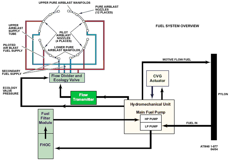
Fuel enters the centrifugal boost stage of the multi-stage pump, passes through the fuel heater/oil cooler (FHOC), the pump inter-stage filter, and to the gears of the high pressure stage of the fuel pump. From the pump discharge, the fuel passes through the motive flow and CVG lockout valve and into the flow scheduling portion of the control.
After metered fuel flow leaves the fuel control, the fuel passes through a flow meter, then continues to the ecology and flow divider assembly.
Two metered fuel flow divider valves distribute fuel flow between the primary atomizers and air blast combustion nozzles based on fuel flow.
The ecology valve piston assembly, inside of the flow divider, travels a preset distance to remove fuel from fuel manifolds after the engine is shutdown, then re-introduces the fuel to the manifold during the next engine startup.
The engine fuel and control system has interfaces with the components/systems that follow:
- Fuel Feed System
- Engine Indication and Crew Alerting System (EICAS)
- Compressor Variable-Geometry Actuator
- Electronic Control Unit (ECU)
- Oil Distribution System