


05/16/19
Overview
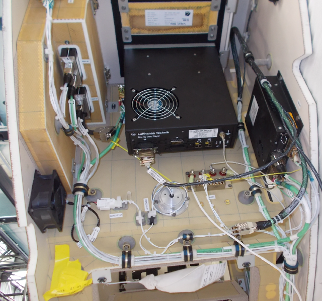
Networked Integrated Cabin Equipment HD (nice® HD) entertainment and cabin management system manufactured by Lufthansa Technik AG.
The ethernet-based network provides audio and video content over a 1000 megabit network. It interfaces to Airshow, iPod, XM radio, water, and lighting systems, etc.
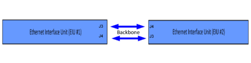
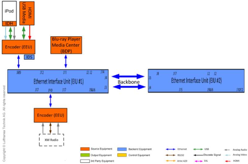
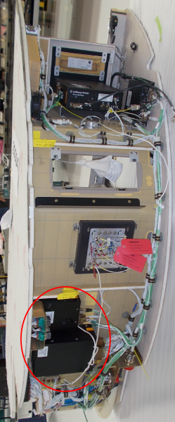
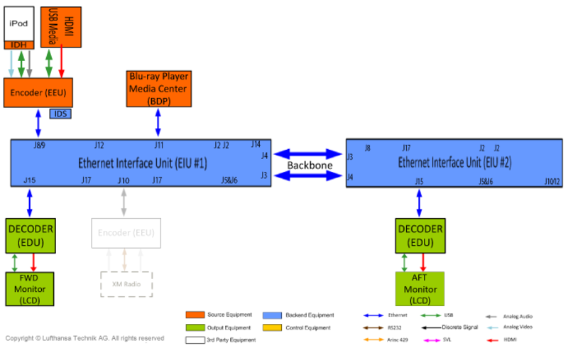
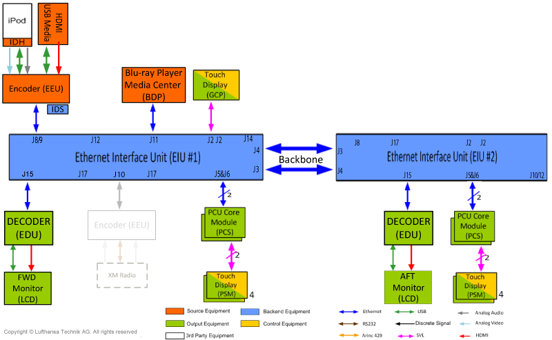
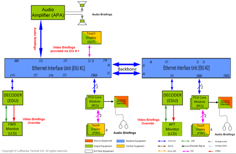
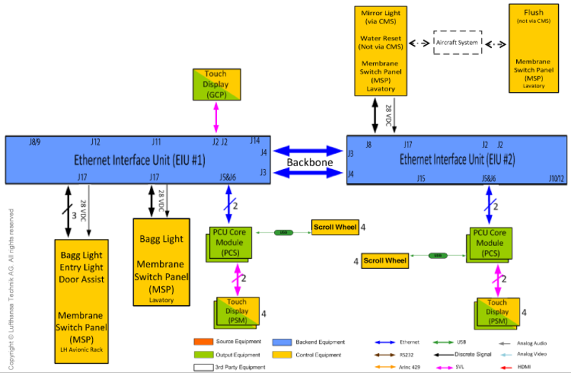
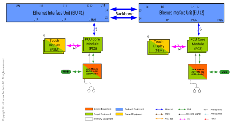
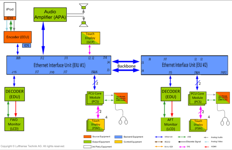
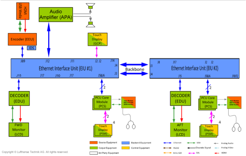
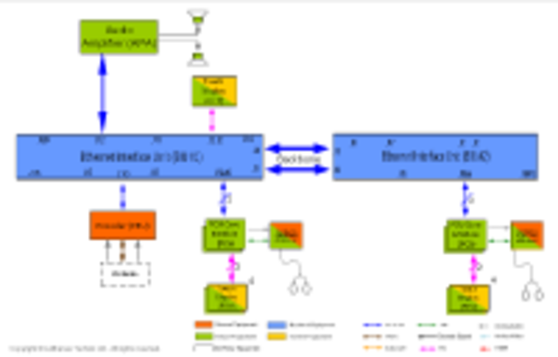
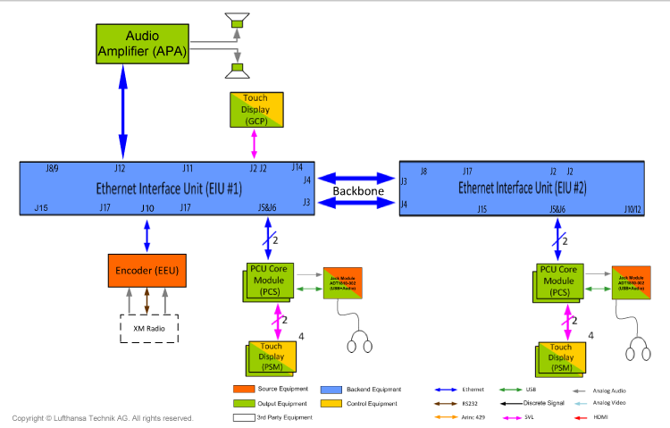
nice® HD controls all cabin functions and distributes audio/video signals and data through one digital wired or wireless Ethernet network. The system comprises a set of LRUs connected to an Ethernet backbone.
Multiple quantities of the same LRU part number may be used in a single system. Installation Position / Location ID determines the LRU "address". The unique installation position of each LRU is defined by location identifier (ID) which is programmed by a jumper integrated into the A/C harness.
The nice® HD Technical User Guide outlines the procedures to 1) acquaint the operator with the technical background of the nice® HD Cabin Management System, and 2) troubleshoot issues that arise during and after initialization.
The Software Load Procedure for nice® HD provides a general overview of the system architecture as required for loading software, it also provides procedures to load and validate the system software.
There are Lighting Presets that can be selected on the assigned Master Seat touch screen: Cabin Menu - Lighting - Lighting Presets. These presets include Boarding Day, Boarding Night, Briefing Day, Briefing Night, Cruise Day, Cruise Night, Takeoff, Landing, Cinema, Breakfast, Lunch, Sleeping, and Reading. The presets set the cabin lighting to a predetermined ambiance. The details of each light in each preset is listed in the attached table CABIN LIGHTING SYSTEM PRESETS.

Ethernet
- IEEE standard
- 1000 BaseT Ethernet supports data rate of 1000Mbits/second 100 BaseT Ethernet supports data rate of 100Mbits/second
- Different signals are routed through same cable (e.g. control commands, audio/video content as MPEG stream).
Digital Video
HDMI - HDMI video signal is capable of supporting resolution up to 1080p.
MPEG Streaming - Flexible Ethernet distribution and routing with Audio signal integrated.
Audio Signal Types
Analog Audio - Interfaces with flight deck Audio Control Panel (ACP)
Digital Audio - MPEG streaming, Ethernet distribution, Flexible routing.
Backend Equipment
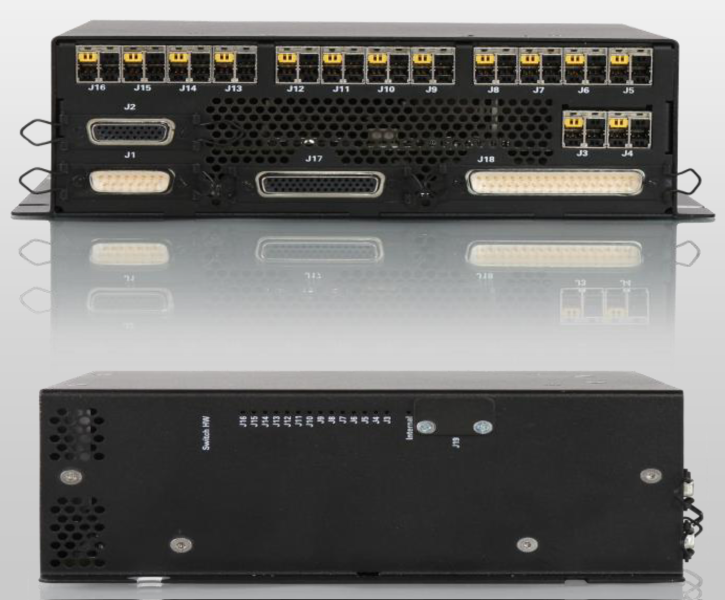
Ethernet Interface Unit (EIU)
Provides Ethernet switching capability, discrete interfaces, relays, and serial bus connections to 3rd party systems.
- 10/100/1000 BaseT Ethernet - 14 each
- Relay outputs (normally open/common/normally closed) - 4 each
- Relay outputs (normally open/common) - 12 each
- Discrete tri-state inputs - 16 each
- Discrete tri-state outputs - 16 each
- USB ports - 2 each
- RS232 port - 1 each
- RS485 port - 1 each
- Serial video out (HDCP protected) - 1 each
- Variable resistor output - 2 each.
Source Equipment
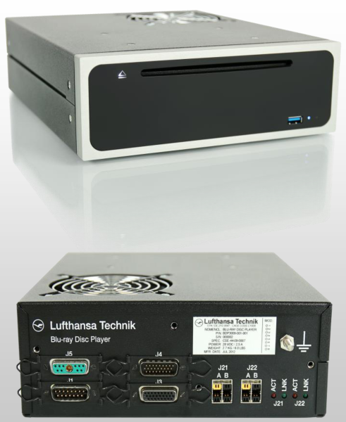
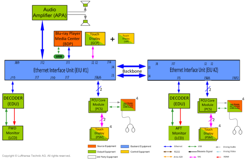
Media Center / Blu-ray Disc Player
- Plays Blu-ray, DVD & CD
- niceviewTM lite 2D Moving Map System (baseline software)
- niceviewTM High-Resolution 3D Moving Map System (software option)
- Media File Server (software option)
- Audio Video on Demand (AVoD) (software option).
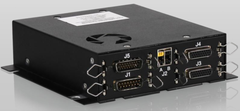
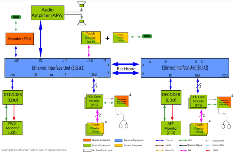
Ethernet Encoder Unit (EEU)
MPEG Encoder that supports iPod Audio/Video, HDMI Input, and XM Radio Audio Entertainment Interfaces.
The EEU has the following interface ports:
- 10/100/1000 BaseT Ethernet - 1 each
- RS232 port - 1 each
- RS485 port - 1 each
- Digital HDMI (HDCP compatible) input - 1 each
- Composite video input - 2 each
- Analog audio input - 2 each
- USB interface - 2 each
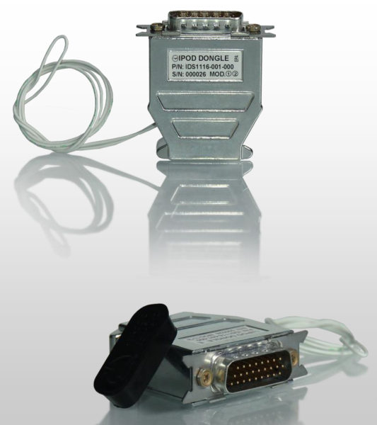
iPhone/ iPod/ iPad Docking Harness
Docking Harness with 0.5m cable length provides interface between iDevices and EEU.

Apple iDevice Authentication Dongle
Enables authentication of iDevices by nice® HD system, and allows control and access of encrypted audio/video content for playback. Dongle connects via USB to the EEU.
XM Radio (Option)
XM Radio is a satellite-based radio system allowing on-aircraft access to over a 100 different music, sports and news channels with coverage over the US, Canada and Mexico.
XM-Radio receiver provides 2 channels of satellite audio and requires an additional EEU encoder.
XM-Radio is controlled from nice® HD Galley Control Panel (GCP) or master seat.
Output Equipment
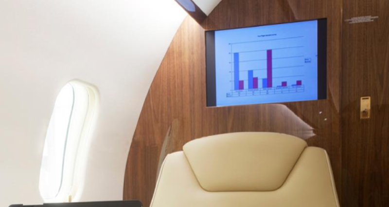
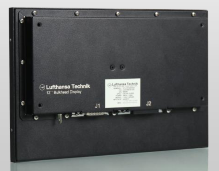
Liquid Crystal Display (LCD)
High-Definition Bulkhead-Mounted LED Backlit LCD Monitor supports multiple video input formats (auto-sensing). The monitor is a 22-inch monitor having a resolution of 1280 x 720 and requires the Ethernet Decoder Unit (EDU) for interface.
The monitor has the following ports:
- USB - 1 each
- Component Video - 1 each
- VGA Input - 1 each
- HDMI Inputs- 2 each
- Discrete Inputs/Outputs - 4 each/1-each
- Analog Audio Stereo Output - 1 each
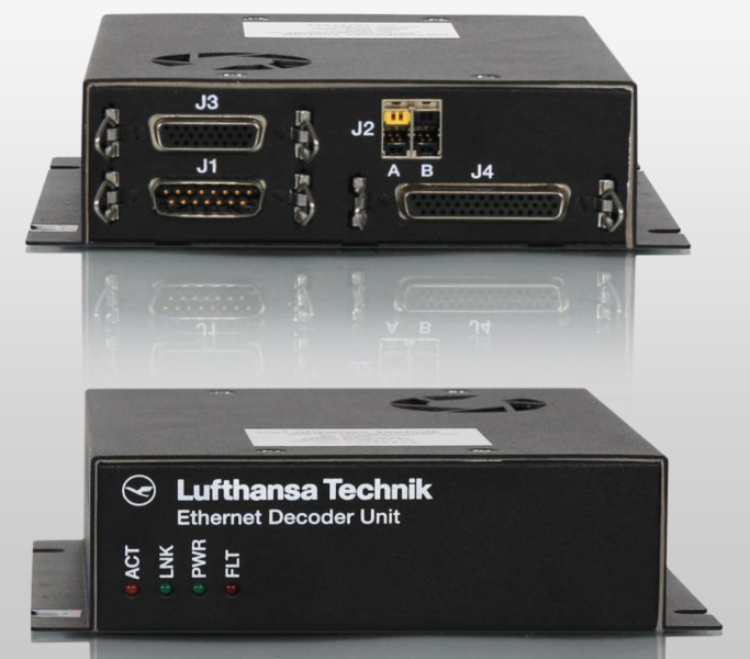
Ethernet Decoder Unit (EDU)
MPEG decoder for bulkhead display. Provides display with serial video and power.
The EDU has the following ports:
- 10/100/1000 BaseT Ethernet - 1 each
- Digital HDMI (HDCP protected) output - 1 each
- Serial video (HDCP protected) output - 1 each
- Analog stereo audio output - 1 each
- 28VDC display power outputs - 2 each
- USB ports - 3 each
- RS232 port - 1 each
- RS485 port - 1 each
- Discrete Inputs/Outputs - 2 each

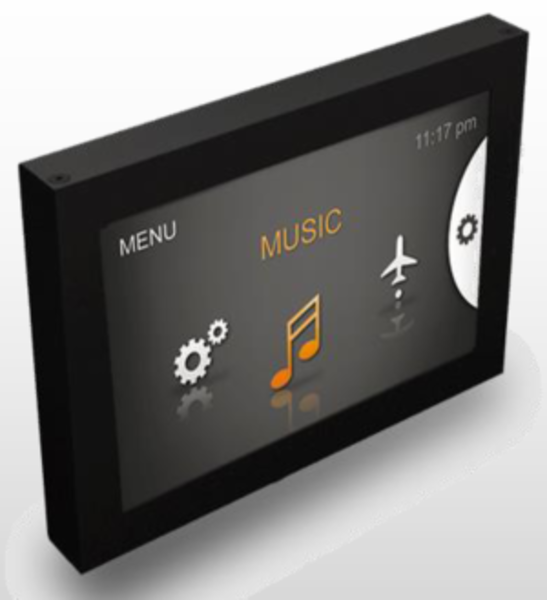
Passenger Control Unit (PCU)
A 4.3 inch Touch-enabled LCD is located at every seat. As an output device, it is used to view video.
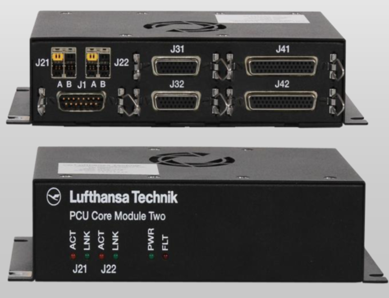
PCU Core Module Two (PCS)
Supports services at the seat:
- MPEG Decoder
- Serial Video & power for seat displays (PCU)
- USB Interface for Scroll Wheel & passenger Ports
- Headphone amplifier
The PCS has the following ports:
- 10/100/1000 BaseT Ethernet - 2 each
- Digital HDMI (HDCP protected) outputs - 2 each
- Serial video (HDCP protected) outputs - 2 each
- 28VDC display power outputs - 2 each
- USB ports for display data - 2 each
- RS232 ports - 2 each
- Discrete Inputs/Outputs - 8 each
- Analog stereo headphone audio outputs - 2 each
- USB Ports (Scroll Wheel) - 2 each
- USB ports (passenger devices) - 2 each
- ANR headphone power outputs - 2 each
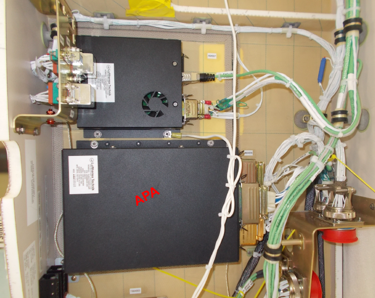
Audio Power Amplifier (APA)
Provides the following:
- Controlled over Ethernet
- Integrated Audio Switching
- Decodes MPEG Audio Stream
- Dynamic Range Compression
- Built-in Crossover
- Integrated Chime Tone Generator
- Dual-mode: Entertainment & PA
The APA has the following ports:
- High-power output channels - 6 each (330 Watts combined)
- 10/100/1000 BaseT Ethernet - 1 each
- Flight deck PA audio input - 2 each
- Flight deck side tone - 2 each
- Analog audio output - 1 each
- Keyline inputs for PA activation - 2 each
- FireWire interfaces - 2 each
- Main power input (Entertainment Audio) - 1 each
- Emergency battery power input (PA only) - 1 each
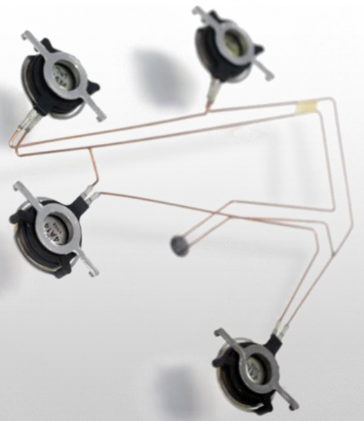
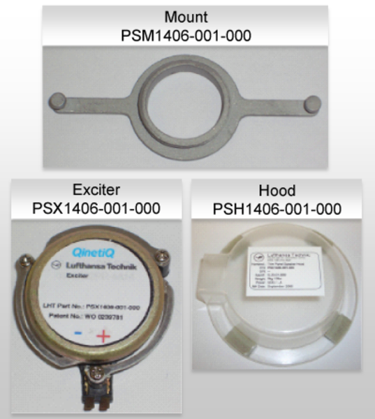
Trim Panel Speaker System
The speakers are installed on sidewall panels. The system consists of an Exciter, Hood & Mount. Exciter is installed on panel using a Mount. The Hood covers Exciter to prevent interference with insulation.
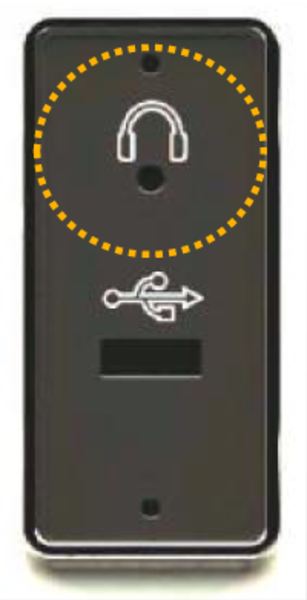
Headphone Jacks
One headphone jack at each seat (in storage box on side ledge). The jacks permit use of noise reduction headsets. Headphone volume control is provided through quick access menu of PCU GUI.
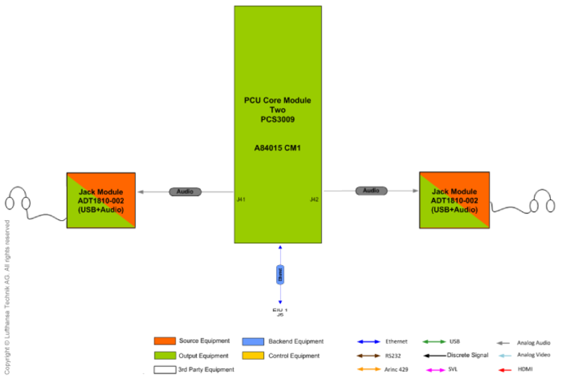
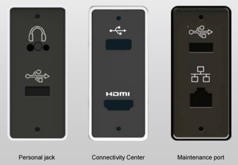
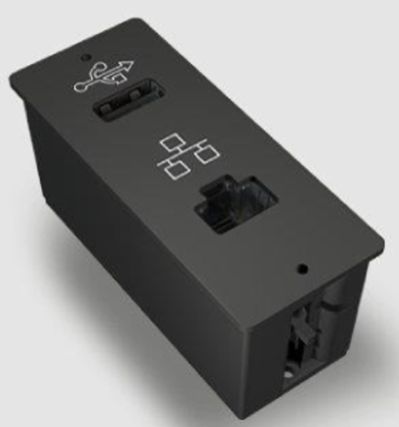
Jack Module
3 variants of jack modules provide connectivity ports for passenger and maintenance use.
Interfaces:
- 3,5 mm stereo headphone jack
- USB
- HDMI
- Ethernet
Control Equipment
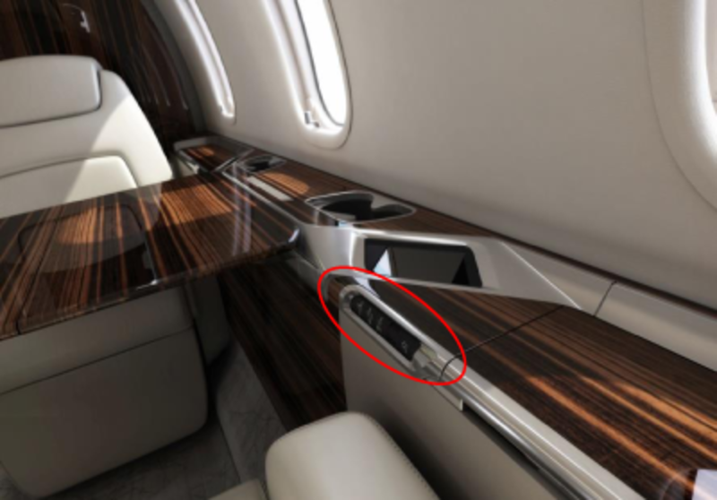
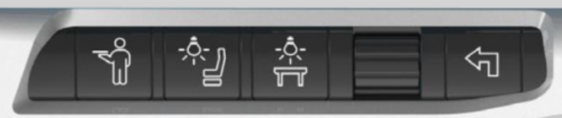
Control Panel
Comprises 4 membrane switches (Attendant Call, Reading Light, Table Light and Return buttons) and a Scroll Wheel (select button). LED backlight provides button status indication (green when selected). Interfaces to PCU Core Module via USB.
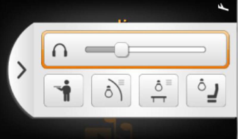
Passenger Control Unit (PCU)
4.3" Touch-enabled LCD that provides intuitive GUI to control lighting, audio/video source selection, and headphone volume.
The PCU interfaces with PCU Core Module Two or with EIU via serial video link. PCU Core Module Two also provides power for the PCU.
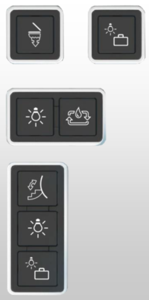
Membrane Switches
Membrane switches control various cabin functions. LED backlight provides button status indication (green when selected). Switches are powered by the DC-system.
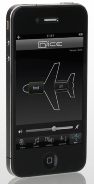
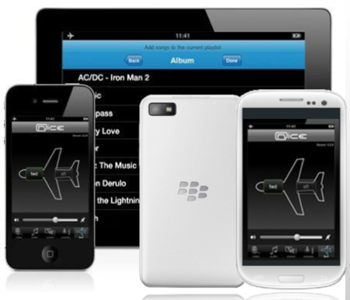
nice® HD Remote Web App
The nice® HD remote Web App enables control of nice® HD system via any mobile device or laptop. The browser based application is resident on the nice® HD system. It is used by entering IP address in the device's web browser.
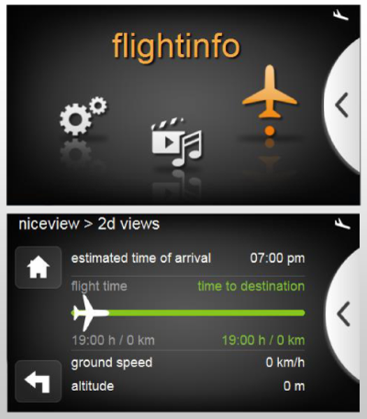
niceview Lite Moving Map System
Flight information viewable on GCP, bulkhead displays and PCUs.
Moving Map terrain scenery viewable on bulkhead displays & GCP
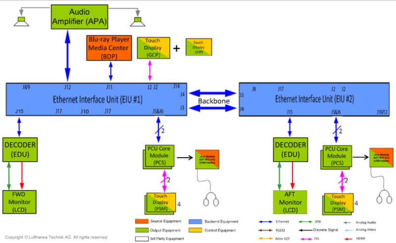
System Interface
Blu-ray:
Passenger Address from Cockpit:
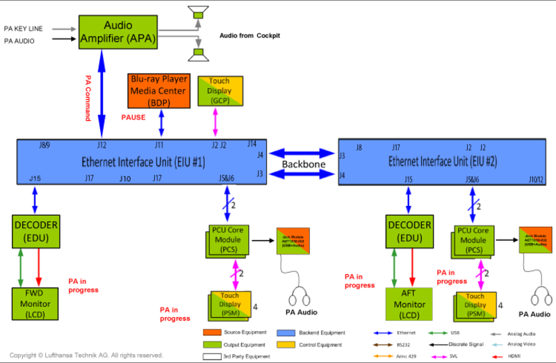
Passenger Address Briefings:
Cabin Control:
USB Media Input to Media Server:
USB Media Input to Monitor and PSM:
USB Media Input to Local Seats:
iPod/iDevice Docking Harness:
Connectivity Center HDMI Connection:
XM Radio:
System Configuration
Software
The Ethernet Interface Unit (EIU) Provides Ethernet switching. It functions as a Configuration Server providing software to all LRUs in the system (Configuration Server Database).
After LRU replacement, the new LRU must be updated by the maintenance technician via the GCP. The new LRU will download the software from the Configuration Server, automatically reboot and return as a fully configured, functional unit.
Each nice® LRU has its own configuration software, ensuring that it functions as intended based on the aircraft wiring and selected options.
A CSDB (Configuration Server Database) contains the configuration software for all LRUs The is specific to each A/C and is delivered on a USB-Stick.
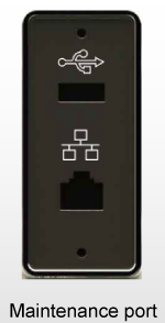
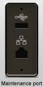
The CSDB is loaded via the maintenance USB port in the left wardrobe. Once loaded, the CSDB resides on EIU 1. LRU software updates are initiated on the GCP via the "CMS equipment" page.
The CSDB must be re-installed from the USB stick if:
- EIU 1 is exchanged
- Software update is provided
If a LRU (other than the EIU 1) is replaced, the CSDB is not required to be reloaded. Only an update is required, initiated from the "CMS equipment" page on the Galley Control Panel.
Unit Identification and Updates
Each unit has a location identifier (ID)* to define installation position and define the specific functionality.
Note*: Simple LRUs (i.e. membrane switch panels and displays) do not require system software and are not specifically monitored by the configuration server
LRU configuration must be reloaded after installing, replacing, swapping, or after a location identifier change.
Download is initiated via GCP "CMS equipment" page.
CSDB Upload Procedure
- Connect USB stick to maintenance port (wardrobe).
- Wait approximately 15 seconds.
- Select "equipment" menu.
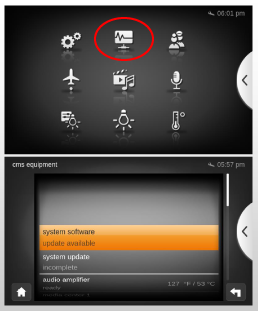
- Select sub menu "CMS equipment".
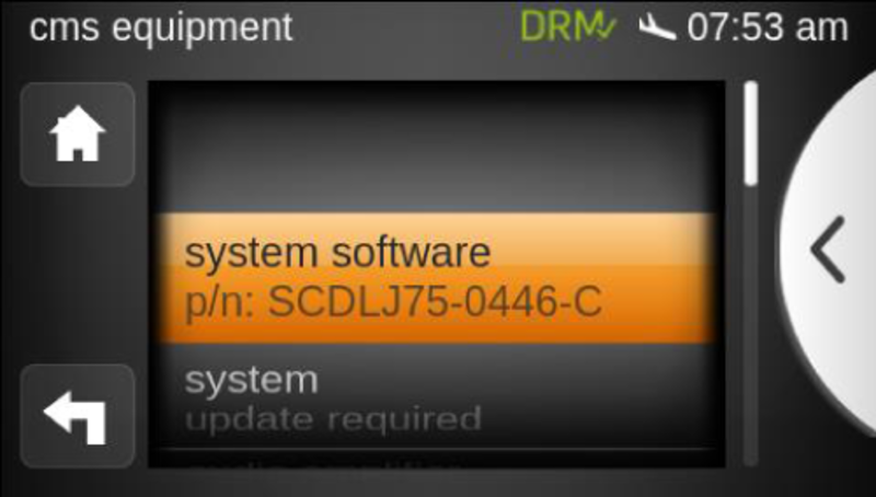
- System software line item will identify that an update is available.
- Select "system software".
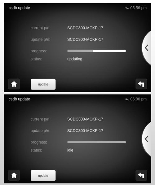
- Verify CSDB P/N.
- Verify status.
- Select "update" button.
- While downloading, a progress bar and status message "updating" is shown.
- When the download is completed, the status message "idle" together with the complete progress bar will be shown on the screen..
- New P/N is displayed.
- USB stick can be removed.
- CSDB update is completed and software is available for download by the system LRUs.
After the above procedure:
- CSDB content has been copied to EIU 1.
- Configuration Server ready to answer update requests.
- New CSDB P/N is reported on GCP "CMS equipment" page.
- LRUs are still in previous configuration and must be updated manually.
Initiate LRU Update
- Each LRU has a unique ID setting.
- The status "update required" will be shown if an update is needed.
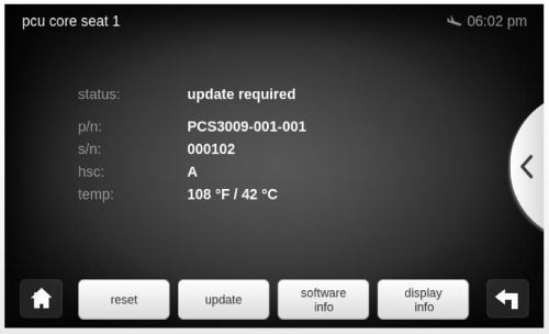
- Select "update" button.
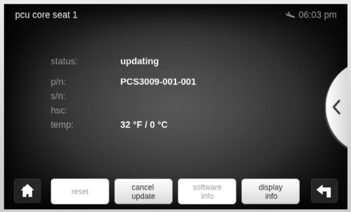
- Unit will show status "updating" during the software load.
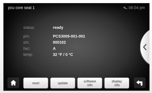
- Unit will show status "ready" after software load is completed.
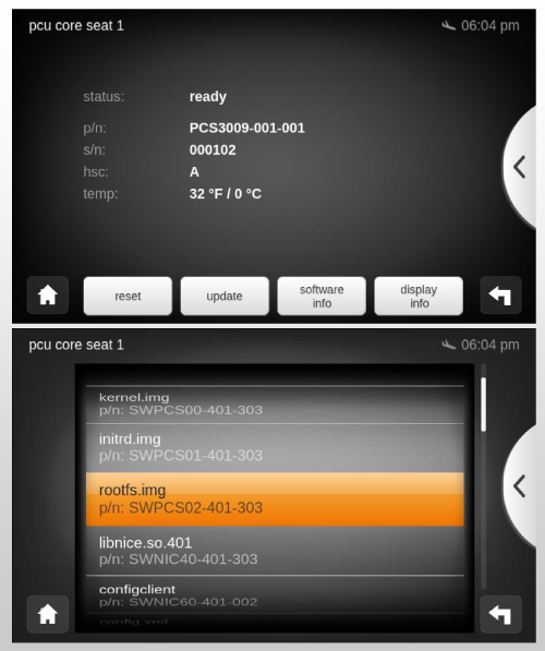
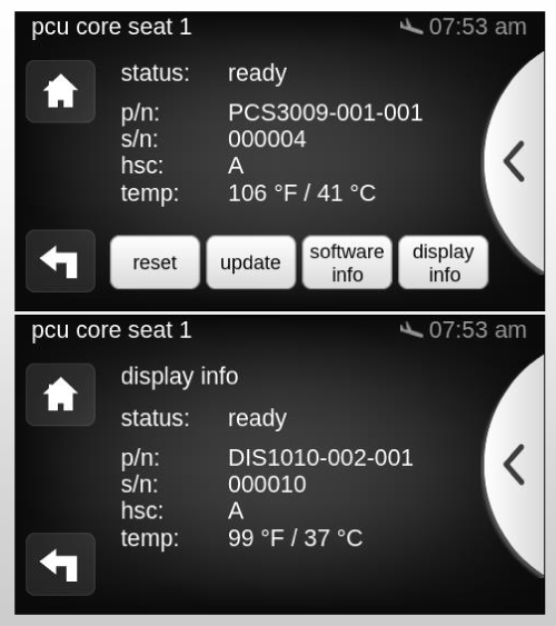
- "software info" button, when selected, shows list of software modules running on selected LRU.
- Display devices are not connected by Ethernet and therefore cannot report their information to the configuration server.
- Information on these components can be obtained from downstream LRU (i.e. PCU Core Module for 4.3" PCU).
- Selecting "display info" will present information relevant to the connected display.
Unit Configuration Update
"update device" Process
- User initiates update on the Galley Control Panel.
- LRU resets automatically.
- LRU downloads software from Configuration Server.
- GUI status indicates "updating".
- LRU reports "ready" after software installation is complete.
General Considerations
- CSDB is aircraft specific.
- Never exchange CSDBs between two different aircraft.
- CSDB always delivered on USB stick.
- CSDB update replaces whole Configuration Server content.
- LRU update is initiated on GCP by the maintenance technician.
LRU Replacement
General
LRUs with same P/N are interchangeable but their configuration must be loaded after installation.
Before doing an LRU update:
- Ensure that all aircraft buses are powered.
- Verify that CMS circuit breakers are pushed in and cabin power is switched ON.
- Wait for the CMS to fully boot.
Some units have special requirements which must be considered:
- For Ethernet Interface Unit (EIU 1), CSDB has to be loaded from USB stick.
- Displays (4.3", 22") do not have field-loadable software. They operate on software that is contained in their interfaced units (PCS, EIU, EDU).
Encoding/Decoding units need to be DRM (Digital Rights Management) enrolled and activated:
- Blu-ray Player
- Ethernet Decoder Unit
- Ethernet Encoder Unit
- Ethernet Interface Unit
- PCU Core Module Two
Note: Blu-ray Player is able to handle multiple region settings for Blue-ray and DVD disks.
DRM Enrollment and Activation
nice® HD uses Digital Rights Management (DRM) system to protect video within the system. Protected video (e.g. Blu-ray Disc movies or HDMI input video with active HDCP) will be encrypted by video encoder (EEU or BDP) before distribution on system. Each decoder (EDU or PCS) decrypts video stream before sending it to any display. Encoder and decoder must use same "key" for encrypting and decrypting, otherwise video can not be displayed. DRM key is unique for each aircraft.
During update process each LRU downloads this key via the internet from the LHT DRM License Server. As long as LRU remains on same a/c, key is valid. No need to download again. LRUs may be swapped between different locations within same a/c without need for another key update. Replacing LRU with Spare part will require a key download from LHT DRM License Server.
DRM Update Procedure
- Power up system and wait until fully booted.
- Select "CMS equipment" page from GCP.
- Wait for amber DRM icon to appear.

- Establish internet connection to nice® HD system through USB port at Maintenance Panel: For Cellphone Tethering (first connect USB cable, then activate tethering on phone). For wired connection, use USB-Ethernet adapter to nice® HD system.
- If the red DRMx icon
 appears, update EIU 1 before establishing tethering connection to the CMS system.
 - When a connection to DRM License Server is made, green icon
 appears in the header.
 - Perform DRM key activation via GUI (this is part of normal LRU update).
- Unit will be shown as DRM enrolled and activated.
Note: The amount of data transferred via the internet connection during update is less than 100 Kbyte per DRM key.
Troubleshooting
Galley Control Panel (GCP) "cms equipment" Page
The "equipment" menu on the GCP shows the status of all components within the nice™ HD Ethernet.
Status Indication on the GCP
The following states can be reported on the GCP:
- "ready" - the unit is working properly with the correct software configuration loaded.
- "updating" - the unit is currently loading the software configuration from the configuration server.
- "update required" - the software configuration installed on the unit does not match the configuration on the configuration server.
- "connected" - the unit is available on the network and fully operational. However it cannot compare its software configuration with the configuration server.
- "not connected" - the unit is not available on the network since the last power cycle.
- "disconnected" - the unit was available on the network after the last power cycle, but the connection has been lost.
LRU LED Status Light Indication
Units with a direct link to the EIU have status indication LEDs. 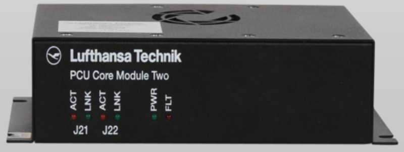
The following table lists the different LEDs and their meaning:
| Label | Description | Indication Interpretation |
|---|---|---|
| PWR | Power | Green = Power available, Off = Power not available, Flashing green = Software loading |
| BAT | Battery Power | Green = Running in battery mode, Off = Running in normal mode or unit is off |
| FLT | Fault | Red = Unit has discovered an error |
| ACT | Ethernet Activity | Flashing Amber = Port is active |
| LNK | Link | Green = Ethernet link is active, Off = No Ethernet link is available |