Overview
The engine indicating system measures parameters of the engine operation and sends electrical signals to the electronic control units (ECUs). Each ECU changes the signals into the data that supplies indications in the flight compartment, on the engine indicating and crew alerting system (EICAS) display.
Each ECU operates fully independently, but checks or fault detection are continuously done by each ECU. The two ECU channels receive inputs, but in normal conditions, only the channel-in-control sends output. If a fail condition of one of the ECU occurs, the other channel operates immediately to send the aircraft the output of the engine indicating sensors.
The engine indicating system measures and displays parameters related to:
- Engine power
- Temperature of the low-pressure (LP) turbine gases
- Engine oil pressure
- Engine oil temperature
- Engine fuel flow
- Engine vibration level
The engine power parameters are measured with N1 sensors, N2 sensors, and N1 compensators.
The N1 sensor measures the speed of the LP rotor and the N2 sensor measures the speed of the high pressure (HP) rotor. The two sensors supply a signal to the ECUs with frequency in proportion to the measured speed of the related rotor. The N1 compensator adjusts the signal from the N1 speed sensor to keep each engine’s thrust/N1 ratio in the correct parameters.
The LP turbine-gases temperature is measured with an exhaust gas temperature (EGT) sensor which includes two probes sets. Each set has four probes electrically connected to send one signal to the related ECU. The two ECUs calculate a value of the EGT probe and change this value to an inter-turbine temperature (ITT).
The engine oil pressure is measured with an oil pressure transducer installed in the left front side of the gear box, below the oil pump housing.
The engine oil temperature is measured with an oil temperature transducer installed in the left rear side of the gear box, below the fuel heater/oil cooler.
The engine fuel flow is measured with a fuel flow meter installed on the forward outer-fan duct.
The engine vibration level is given by a vibration sensor that measures engine vibration and sends continuous engine-vibration data to the ECU. The sensor can also be connected to a ground analyzer to balance the fan rotor assembly on the ground.
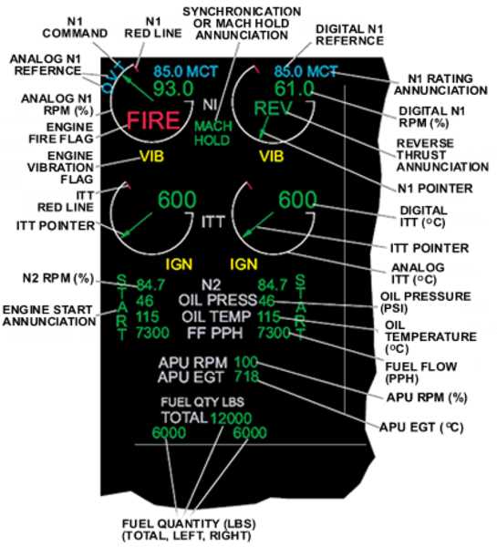
The engine operating parameters (N1 rpm, N2 rpm, ITT, oil pressure, oil temperature, and fuel flow) and engine related annuncitations are shown as one integral display, in the engine indicating system (EIS) area of the EICAS display. The EIS area also shows with the engine displays, fuel quantity indications and auxiliary power unit (APU) indications.