


09/17/21
Overview
The avionics cooling system removes the hot air that comes from the avionics equipment installed in the left and right equipment racks. It also removes the hot air that comes from the adaptive flight-display units (AFD) that are in the flight compartment.
The cabin inverter cooling fan gets cold air from the belly fairing and blows around the cabin inverter installed in the aft equipment-compartment (For CH300 and on A/C 20501 to 20902 for CH350).
Note:
For the avionics systems, cooling is done through the removal of hot air given off by the equipment. It is not done through the supply of cool air to the equipment.
Hot air from the equipment racks and the flight compartment's AFD is moved out of the aircraft through flexible and rigid low pressure ducts. This configuration keeps weight to a minimum and helps in the ducts' installation and removal.
The flexible ducts are made as follows:
- With a layer of silicone-coated glass-fabric hose. The hose is made stronger with a coil made out of metallic or non metallic wire.
- Inlet and outlet ends have two or three layers of silicone made stronger by fiberglass.
The rigid ducts are made as follows:
- With one or more layers of fiberglass phenolic resin composite material made stronger with fiberglass. The ducts are locally made stronger with more layers of material at the pneumatic and structural connections.
- With an internal electrically conductive layer.
CH300:

CH350:
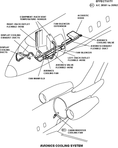
Equipment Rack Vent Temperature Sensor
Two vent temperature sensors are used to measure the ambient temperature in the equipment racks.
One sensor is installed at the top of the left equipment rack and is identified as the avionic-rack vent temperature-sensor No. 1. The other sensor is installed at the top of the right equipment rack and is identified as the avionic-rack vent temperature-sensor No. 2.
Each vent temperature-sensor has a fan and two sensor elements installed on a circuit board. The circuit board is installed into a plastic housing.
For their operation, the fans that are installed in the vent temperature sensors are supplied with 28 VDC electrical power. For the fan installed in avionic-rack vent temperature-sensor No. 1, the 28 VDC comes from junction box (JB) No. 1. For the fan installed in avionic-rack vent temperature-sensor No. 2, the 28 VDC comes from JB No. 2.
While it operates, each vent temperature sensor fan makes air movement. This air movement causes some of the ambient air in the equipment racks to go through two rectangular openings found on the sensors' housing. When the air goes through each sensor housing, it is measured and changed into electrical signals by two sensor elements. One of the sensor elements sends its data to IAS controller No. 1 while the other sensor element sends its data to IAS controller No. 2.
The IAS controllers use the data received from the vent temperature sensors to control the operation of the avionics cooling fan and the avionics cooling valve.


Avionics Cooling Fan
The avionics cooling fan is installed below the aircraft floor, near FS344.00. Its forward end is attached to the fan manifold. Its aft end is attached the fan silencer.
When it operates, the avionics cooling fan sends the hot air found in the avionics cooling system ducts and hoses overboard through the cabin-pressure control system outflow valve.
The avionics cooling fan is a mixed flow, mono-stage fan. The fan enclosure and stator blades are made out of light aluminum alloy. The impeller is made out of a composite material.
A check valve is installed on the air outlet of the avionics cooling fan. It prevents air to flow in the incorrect direction when the fan does not operate.
The 28 VDC electrical power and all electrical signals related to the operation of the fan go through a control box installed on the fan enclosure. The control box is used as an interface. It also controls the fan rotational speed. When a low fan rotational speed is sensed, the IAS controllers are told about it through a discrete output.
Power distribution and control of the avionics cooling fan is as follows:
- The 28 VDC electrical power necessary to operate the fan comes from the left and right dc power centers (DCPC).
- The speed of the fan, which can be one out of two possible speeds, is controlled by the IAS controllers (usually by IAS controller No. 1, but if IAS controller No. 1 becomes unserviceable, control is given to IAS controller No. 2).
- A thermal switch is installed in the fan motor windings. If the fan becomes too hot, the thermal switch cuts off the fan's supply of electrical power.
- Communication between the fan and the IAS controllers is done through discrete inputs/outputs.


Avionics Cooling Valve
The avionics cooling valve is installed below the aircraft floor, forward of the wing box, in the pressurized area. It is connected to the avionics exhaust-flexible duct and attached to the aircraft structure with an adapter.
When it is opened, the avionics cooling valve sends overboard the hot air found in the avionics cooling system ducts and hoses.
The avionics cooling valve has machined interface flanges. Its body is made out of an aluminum alloy.
The avionics cooling valve is opened or closed with a 28 VDC electrical supply that comes from the IAS controllers (usually by IAS controller No. 1, but if IAS controller No. 1 becomes unserviceable, control comes from IAS controller No. 2), through the avionics valve relay K97. The avionics valve relay K97 is found in JB No. 3.
The avionics cooling valve can be manually opened or closed with the external lever found on the avionics cooling valve itself. As a secondary function, the lever gives a visual indication of the avionics cooling valve position. The avionics cooling valve full-open and full-closed position are monitored by the IAS controllers.


Fan Manifold
The fan manifold is installed below the aircraft floor near FS326.00. It connects the rack outlet flexible-hoses and the display cooling exhaust-ducts to the avionics cooling fan.
The fan manifold collects the hot air that comes from the equipment racks and the flight compartment avionics displays and sends it, as applicable, in the direction of the avionics cooling fan or the avionics cooling valve.

Fan Silencer
The fan silencer is installed below the aircraft floor, aft of the avionics cooling fan, between FS344.00 and FS392.00. It is a rigid duct and it is connected to the aft end of the avionics cooling fan and to the fan silencer extension.
The fan silencer sends the hot air that comes from the avionics cooling fan to the cabin-pressure control system outflow valve. It also decreases the noise and the air turbulence caused by the avionics cooling fan.
To decrease the noise caused by the avionics cooling fan, the fan silencer has a cover made out of three layers of fiberglass. Each layer of fiberglass is isolated with a glass-fabric liner.

Display Cooling Ducts
The display cooling ducts are installed behind the flight compartment AFD and are connected to the display cooling exhaust-ducts. They are made up of the parts that follow:
- Two rigid ducts
- One flexible hose
The display cooling ducts collect the hot air that comes from the flight compartment AFD and send it to the display cooling exhaust-ducts.

Display Cooling Exhaust Ducts
The display cooling exhaust-ducts are installed below the flight compartment floor. They connect the display cooling ducts to the fan manifold and to the avionics valve flexible-hose.
The display cooling exhaust-ducts are made up of the parts that follow:
- Two flexible hoses
- One tee joint
The display cooling exhaust-ducts send hot air from the display cooling ducts to the fan manifold and avionics valve flexible hose.

Avionics Valve Flexible Hose
The avionics valve flexible-hose is installed below the flight compartment and forward passenger compartment floors. It connects the display cooling exhaust-ducts to the avionics exhaust flexible-duct.
The avionics valve flexible-hose sends the hot air that comes from the display cooling exhaust-ducts to the avionics exhaust flexible-duct.

Rack Outlet Flexible Hose
There are fourrack outlet flexible-hoses installed in the aircraft: the left and the right rack outlet flexible-hoses.
The left rack outlet flexible-hoses are installed behind the left side equipment rack and in the lower fuselage. The right rack outlet flexible-hose is installed behind the right side equipment rack and in the lower fuselage. The lower rack outlet flexible-hoses are connected to the fan manifold.
The rack outlet flexible-hoses collect the hot air that comes from the equipment-racks and send it to the fan manifold.

Avionics Exhaust Flexible-Duct
The avionics exhaust flexible-duct is installed below the passenger compartment floor. It connect the avionics valve flexible-hose to the avionics cooling valve.
The avionics exhaust flexible-duct sends the hot air that comes from the avionics valve flexible-hose to the avionics cooling valve.

Fan Silencer Extension
The fan silencer extension is installed in the lower fuselage. It connects the fan silencer to the acoustic hood. The fan silencer sends hot air that comes from the fan silencer to the acoustic hood.
The fan silencer decreases the noise caused by the avionics cooling fan. The acoustic hood is made of panels that are attached to the floor structure. The acoustic hood is installed above the cabin-pressure control system outflow-valve. To decrease the noise caused by the avionics fan, the acoustic hood panels have insulation blankets. The acoustic hood is a part of the aircraft structure.

Cabin Inverter Cooling Fan (For CH300 and on A/C 20501 to 20902 for CH350)
The cabin inverter cooling fan is installed in the aft equipment-compartment, near FS688.45. Its inlet end is attached to the plenum duct which is installed on belly fairing. Its outlet end is attached to the duct.
When it operates, the cabin inverter cooling fan gets cold air from the belly fairing and blows around the cabin inverter. The cabin inverter cooling fan provides additional air cooling flow to prevent the cabin inverter from overheating under extreme temperature/altitude/load conditions.
The cabin inverter cooling fan is a simplex fan. It is a single-speed electronically commutated fan operating on nominal fault excitation of 28 VDC. There is an enable function that lets the fan to turn on or off remotely. The nominal fan intake diameter is 4.2 in and the exhaust diameter is 4.00 in.

11/10/15
System Operation
Ambient temperature (usually hot air) in the equipment racks is measured and changed into electrical signals by two vent temperature sensors. The electrical signals are then sent to the IAS controllers. The IAS controllers use the data to control the operation of the avionics cooling fan and the avionics cooling valve. The fan can be energized or de-energized, and the valve can be opened or closed.
When the avionics cooling fan is energized and the avionics cooling valve is closed, the hot air that comes from the equipment racks and the AFD is pulled into a low-pressure ducting system and sent overboard through the cabin-pressure control system outflow valve.
When the avionics cooling fan is not energized and the avionics cooling valve is opened, the hot air in the low-pressure ducting system is sent overboard through the avionics cooling valve.
IAS controller No. 1 usually controls the operation of the avionics cooling system, but if IAS No. 1 becomes unserviceable, control is given to IAS controller No. 2.
Decision by IAS controller No. 1 or No. 2 to energize the avionics cooling fan or the avionics cooling valve is related to parameters that follow:
- The avionics cooling system mode of operation (usual or degraded)
- The condition (serviceable or unserviceable) of the avionics cooling fan and the avionics cooling valve.
The avionics cooling system has two modes of operation. They are as follows:
- Usual mode of operation
- Degraded mode of operation

Usual Mode of Operation
In the usual mode of operation, the IAS controller No. 1 controls the avionics cooling fan and the avionics cooling valve. At all times the system operation is monitored by the two IAS controllers. The system operation is as follows:
- On the ground the fan is operated in the high speed mode
- In flight the fan is operated in the low speed mode. The fan will operate in the high speed mode when the ambient temperature in the avionics rack is 50°C for 60 seconds.
Note:
In the two cases, the avionics cooling valve is kept closed.
Automatic air extraction source selection logics (independent of the aircraft altitude or operation) are also implemented to cater for fan or valve failure:
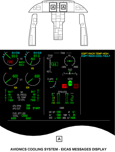
- If the fan is detected failed, the valve is driven open. A fault EQPT RACK COOL FAULT advisory message is posted on EICAS and logged on the MDC.
- If the valve is detected failed closed, the fan continues to operate ON. A fault EQPT RACK COOL FAULT advisory message is posted on EICAS and logged on the MDC.
- If the avionics valve is detected failed open and the aircraft altitude is above 10,000 ft (to avoid cooling by both fan and valve at high differential pressure), the fan shall be turned off by IASC and EQPT RACK COOL FAULT advisory message is posted on EICAS and logged on the MDC.
- When a small overheat (65°C [149°F] during 60 seconds) is detected in the left or right avionics rack while the aircraft altitude is above 10,000 ft, the AVV is commanded to open and the fan is OFF.
Degraded Mode of Operation
In order to ensure system safe operation in the event of the normal in-control controller failure, a degraded mode, involving system control through IAS Controller No. 2 is activated. In case of failure of IAS Controller No. 1 channel A, EAS Controller No. 2 channel A takes control.
IASC Controller No.1 channel A is detected failed when valve and fan are detected failed or an internal failure of channel A.
Unsatisfactory operation of IAS controller No. 1 is sensed by IAS controller No. 2 when one of the condition that follows occurs:
- On the IAS controllers cross-talk bus, no ARINC signal is received by IAS controller No. 2.
- On the IAS controllers cross-talk bus, IAS controller No. 1 indicates that the avionics cooling system does not operate.
In degraded mode, the avionics fan is always operated at the same speed selection logic as normal operation (usually on high speed, but on low speed during single bleed operation). If the fan is failed, the avionics valve takes over.
Operation Limitations
Dispatch with fan failed is not allowed for smoke penetration concerns. Loss of adequate ventilation in the avionics racks does not result in an overheat condition and thus cannot be detected. However, if an overheat condition occurs, it is detected by a dedicated dual sensing element, ventilated temperature sensor installed in the avionics racks. This failure is indicated top the pilot by an EQPT RACK TEMP HIGH caution message, and may result in mission interruption.
Warning:
Obey all the safety precautions when you do maintenance on or near the air-conditioning system. If you do not obey the safety precautions, you can cause injury to persons and damage to the equipment.
Caution:
Do not remove the bond tab from the avionics cooling fan. If you do this, you can cause damage to the avionics cooling fan.
Caution:
Be careful when you do work on or near the aircraft ducts compression of the duct insulation could cause hot spots or decreased airflow. This can cause damage to the ducts and to the aircraft.
The open/close lever on the avionics cooling valve can be useful to release the aircraft for flight.
If the avionics cooling fan is unserviceable, the aircraft can be released for flight if the following conditions are met:
- Avionics cooling fan check valve is closed
- Avionics cooling valve remains in the open position
The procedure described above must be followed to ensure air pulled through the avionics cooling valve comes from the equipment racks and avionics displays.
Aircraft operation is then limited to the following parameters:
- Flight is limited at or below flight level (FL) 300 (30,000 ft or 9,144m)
- Ground operation with the avionics systems energized is limited to 20 minutes when the outside air temperature is more that 86°F (30°C).

Displays
The EQPT RACK TEMP HIGH caution message will show when the temperature in one of the two equipment racks is high.
The EQPT RACK COOL FAULT advisory message will show when a fault has been sensed in the avionics equipment rack cooling system.
The EICAS messages that follow are related to the avionics cooling system:
| EICAS MESSAGE | LEVEL (COLOR) |
|---|---|
| EQPT RACK TEMP HIGH | CAUTION (amber) |
| EQPT RACK COOL FAULT | ADVISORY (cyan) |
11/10/15
System Interface
The avionics cooling system has interfaces with the systems/components that follow:
- Integrated Air System (IAS) Controller
- Outflow Valve
- DC Power Center (DCPC)
- Junction Box JB1
- Junction Box JB2
- Junction Box JB3
- Engine Indication and Crew Alerting System (EICAS)
- Adaptive Flight-Display Unit
System Monitoring
Even if the avionics cooling system becomes unserviceable, hot air can not collect behind the avionics displays. Because of natural convection, the hot air will instead be sent in the direction of the windshield through special ventilation holes.
Insufficient ventilation in the equipment racks is sensed by the equipment-rack vent temperature-sensors. This condition is shown by the EQPT RACK TEMP HIGH caution message on the EICAS.
Insufficient ventilation in the equipment racks can cause mission interruption. Independently of the aircraft altitude or the avionics cooling system mode of operation (usual or degraded), the actions that follow occur automatically:
- If the avionics cooling fan is sensed to be unserviceable, the avionics cooling valve is opened and the EQPT RACK COOL FAULT advisory message is shown on the EICAS. The fault is also recorded on the maintenance diagnostic computer (MDC).
- If the avionics cooling valve is sensed to be unserviceable and in the closed position, the avionics cooling fan is energized and the EQPT RACK COOL FAULT advisory message is shown on the EICAS. The fault is also recorded on the MDC.
- If the avionics cooling valve is sensed to be unserviceable, in the open position, and the aircraft is not on the ground, the avionics cooling fan is de-energized unless the left or right equipment-rack ambient temperature is sensed to be too hot.
10/13/20
Component Location Index
| Component Location Index | |||
|---|---|---|---|
| IDENT | DESCRIPTION | LOCATION | IPC REF |
| MT39 | EQUIPMENT-RACK VENT TEMPERATURE-SENSOR (LH) | ZONE(S) 211 | 21-23-01 |
| MT30 | EQUIPMENT-RACK VENT TEMPERATURE-SENSOR (RH) | ZONE(S) 212 | 21-23-01 |
| B3 | AVIONICS COOLING FAN | ZONE(S) 141 | 21-23-05 |
| MPE14 | AVIONICS COOLING VALVE | ZONE(S) 141 | 21-23-09 |
| - | FAN MANIFOLD | ZONE(S) 141 | 21-23-11 |
| - | FAN SILENCER | ZONE(S) 141 | 21-23-13 |
| - | DISPLAY COOLING DUCTS | ZONE(S) 212 | 21-23-15 |
| - | DISPLAY COOLING EXHAUST-DUCTS | ZONE(S) 212 | 21-23-17 |
| - | AVIONICS VALVE FLEXIBLE-HOSE | ZONE(S) 141 | 21-23-19 |
| - | RACK OUTLET FLEXIBLE-HOSE | ZONE(S) 211/212 | 21-23-21 |
| - | AVIONICS EXHAUST FLEXIBLE-DUCT | ZONE(S) 141 | 21-23-23 |
| - | FAN SILENCER EXTENSION | ZONE(S) 141/142 | 21-23-27 |
| A207 | CABIN INVERTER COOLING FAN | ZONE(S) 312 | 21-23-31 |