


Overview
The temperature control and indication system controls the temperature of air supplied to the passenger and flight compartments. The temperature is controlled by the COCKPIT and CABIN temperature selectors on the AIR COND/ BLEED control panel. Sensors measure the air temperature in each zone.
Temperature control is done by adding hot trim air to the cool air supplied by the air-conditioning system. Sensors monitor the temperature of air in the supply ducts. The integrated air system (IAS) controllers control the hot-air regulating and shutoff valves (HARSOVs) to control the amount of hot air added to the conditioned air.
Some of the components of the temperature control and indication system (trim air) are trim-air ducts, made of high-pressure ducting. The trim-air ducts supply the flight and passenger compartments with hot air from the precooler outlet. Flexible joints along the ducting cope with manufacturing and installation tolerances, structural movement, and thermal expansion of the pipes. Trim-air ducts are insulated so that the touch temperature does not exceed 200°C (392°F). The insulation shell is drilled with small holes at approximately every 20 in. (50.80 cm). Air leakage from the ducts is collected in the shell and exhausted through the holes that direct air onto the leak detection loops. Insulated ducts with flanges are attached end-to-end by means of band clamps covered with coupling covers made of silicon rubber.

Hot Air Check Valve
There are two hot air check valves (HACKVs) in the aft baggage compartment. They are on the trim-air bulkhead adapters. They have two flappers installed on a hinge pin. A spring keeps the flappers in the closed position. The HACKVs prevent reverse flow of bleed air through the HARSOVs. They also prevent cabin depressurization if a trim air duct failure.


Trim Air Bulkhead Adapter
There are two trim air bulkhead adapters on the lower part of the aft pressure bulkhead. They connect the cabin trim duct and HACKV to the cabin feed duct and the flight compartment trim duct and HACKV to the flight compartment feed duct.


12/16/20
Hot Air Regulating and Shutoff Valve
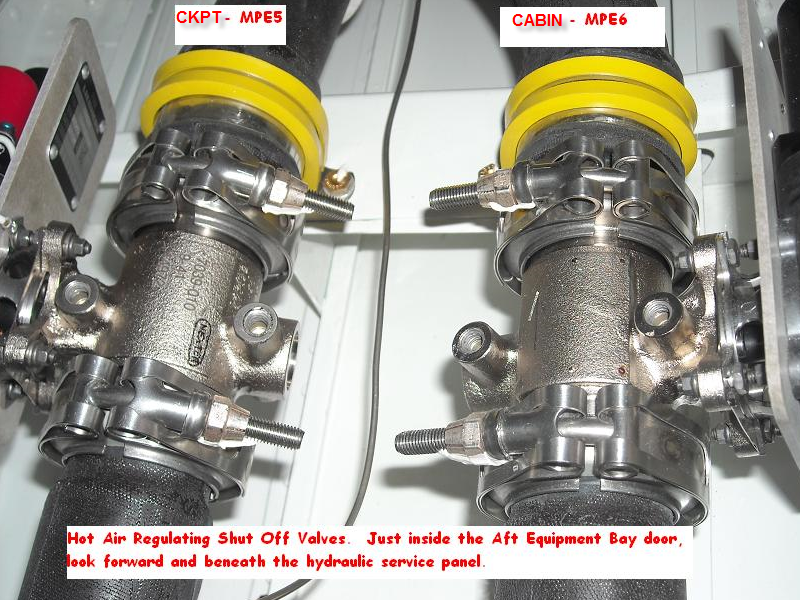
There are two HARSOVs installed in the aft equipment compartment that control the hot air flow from the trim split duct to the distribution system. The HARSOV1 (MPE5) is located to the left and it controls the hot air supplied to the flight compartment. The HARSOV2 (MPE6) is located to the right and it controls the hot air supplied to the passenger compartment.
Each HARSOV has an aluminum body and butterfly valve. The 28 VDC motor operates the butterfly valve. Electrical power is supplied by the IAS controller. The butterfly valve shaft is guided by two diametrically opposed self-lubricating rings. Two micros-witches monitor the FULL-CLOSED and FULL-OPEN positions.


Precooler Crossover Valve (MPE11)
There is one precooler crossover valve (PCV) in the aft equipment compartment. It connects the pack inlet duct and the pack outlet duct. The PCV balances the airflow distribution to the air conditioning system and to the trim-air ducting, depending on the zone temperature demand. The PCV can also isolate the air-conditioning system from the trim air ducting, if required.
Note:
The pack inlet duct and pack outlet duct are components of the intermediate-pressure bleed-air system.
The PCV is operated by a 28 VDC motor. FULL-CLOSED and FULL-OPEN positions are monitored by micros-witches The valve body is made of stainless steel and insulated by a removable insulating jacket to keep the touch temperature below 200°C (392°F).
A lever on the valve lets the PCV be manually positioned and secured for dispatch in the CLOSED position. The upstream flange has a notch to make sure it is properly installed.


11/08/15
Flight Compartment Duct Temperature Sensor
There is one flight compartment duct temperature sensor (DTS) in the aft baggage compartment, in the flight-compartment duct, downstream of the mix manifold. It measures the temperature of the air supplied to the flight compartment distribution system and sends this data to the IAS controller.
Note:
The flight compartment duct is a component of the flight compartment distribution system.


11/08/15
Cabin Duct Temperature Sensor
There is one cabin DTS, installed in the aft baggage compartment, in the rigid tee duct, downstream of the mix manifold. It measures the temperature of the air supplied to the passenger compartment air distribution system and sends this data to the IAS controller.
Note:
The rigid tee duct is a component of the passenger compartment distribution system.


Cabin Ventilated Temperature Sensor
There is one cabin-ventilated temperature sensor (VENTS), installed on the right side, near the mid point of the passenger compartment. It measures the ambient temperature of the air in the passenger compartment and sends this data to the IAS controller. The sensor is made of a sensing element and a fan, contained in a plastic housing. The fan is supplied with 28 VDC from the IAS controller. The fan extracts ambient air into the housing. This circulates the air around the sensing element which then accurately measures the air temperature.


Flight Compartment Ventilated Temperature Sensor
There is one flight-compartment VENTS, installed in the flight compartment. It measures the ambient temperature of the air in the flight compartment and sends this data to the IAS controller. The sensor is made of a sensing element and a fan, contained in a plastic housing. The fan is supplied with 28 VDC from the IAS. The fan extracts ambient air into the housing. This circulates the air around the sensing element which then accurately measures the air temperature.


Hot-Air Temperature Sensor
There is one hot-air temperature sensor (HATS), installed in the aft equipment compartment, in the APU discharge duct. It measures the temperature of the air in the trim air line. The HATS output signal is used by the IAS controller to control the right flow control valve (FCV), which then controls the temperature of the trim air.
Note:
The APU discharge duct is a component of the intermediate-pressure bleed-air system. The flow control valve is a component of the filtering and flow control system.

Pack Inlet Temperature Sensor
There is one pack inlet temperature-sensor (PITS), installed in the aft equipment compartment, in the pack inlet duct. The PITS measures the temperature of the air supplied to the air conditioning system and sends this data to the IAS controller.
Note:
The pack inlet duct is a component of the intermediate-pressure bleed-air system. The precooler is a component of the filtering and flow control system.

11/08/15
Midtrim Discharge Duct
There is one mid-trim discharge duct, installed in the aft equipment compartment. It connects the pack outlet duct to the forward-trim discharge duct .


11/08/15
Forward Trim Discharge Duct
There is one forward-trim discharge duct, installed in the aft equipment compartment. It connects the mid-trim discharge duct to the trim split duct.

11/08/15
Trim Split Duct
There is one trim split duct, installed in the aft equipment compartment. It connects the forward-trim discharge duct to the HARSOVs. The trim split duct separates the trim air and supplies both the flight compartment and passenger compartment distribution systems.


11/08/15
Flight Compartment Trim Duct
There is one flight-compartment trim duct, installed in the aft equipment compartment. It connects the left HARSOV to the left HACKV.

11/08/15
Flight Compartment Feed Duct
There is one flight-compartment feed duct, installed in the aft baggage compartment. It is connected to the HACKV. The flight-compartment feed duct injects hot air into the conditioned air supply of the flight compartment distribution system, downstream of the mix manifold.
Note:
The mix manifold is a component of the passenger compartment distribution system.

11/08/15
Cabin Trim Duct
There is one cabin trim duct, installed in the aft equipment compartment. It connects the right HARSOV to the right HACKV.


11/08/15
Cabin Feed Duct
There is one cabin feed duct in the aft baggage compartment. It connects the HACKV to the cabin trim injector.

11/08/15
Cabin Trim Injector
There is one cabin trim injector, installed in the aft baggage compartment. It connects the cabin feed duct to the mix manifold. The cabin trim injector supplies hot air to the conditioned air downstream of the mix manifold.

11/08/15
System Operation
The trim air is supplied with pre-cooled bleed air from the filtering and flow control system. The HATS and the PITS measure the temperature of the air entering the HARSOVs and the air conditioning system (also known as the pack), and send this data to the IAS controller (IASC). The HARSOVs control the bleed air supplied to the flight compartment and cabin trim duct injectors. The injectors inject air into the air supply from the HARSOVs and send this to the mix manifold. The mix manifold supplies conditioned air at the required temperature to the flight compartment and the passenger compartment. The flight compartment and cabin duct temperature sensors measure the temperature in the ducts downstream of the mix manifold and send this data to the IASC. The IASC uses this information to control the HARSOVs, along with the temperature data from the HATS and the PITS.
The ambient air temperature in the passenger compartment and cabin is monitored by the appropriate VENTS. The aircrew can control the flight compartment and passenger compartment air temperature through the COCKPIT and CABIN temperature selectors on the AIR COND/BLEED control panel. The COCKPIT and CABIN temperature selectors send signals to the HARSOVs.
The AIR COND/BLEED control panel installed in the flight-compartment center pedestal controls the temperature control and indication system. The COCKPIT and CABIN temperature selectors on the AIR COND/BLEED control panel control the temperature in the flight compartment and passenger compartment. They send signals to the IAS controllers to control the air temperature of each zone in the range of 59 to 95°F (15 to 35°C).
When the MAN TEMP push button annunciator (PBA) on the AIR COND/BLEED control panel is pushed and the light goes out, the automatic mode is set for each of the configurations. When the MAN TEMP PBA is pushed and the light comes on, the manual mode is set.
The trim-air system has three configurations of operation as follows:
- NORM
- TRIM AIR ONLY
- PACK ONLY
NORM
In this configuration, the flight compartment and passenger compartment temperature is controlled by the IASC, which controls the amount of hot air injected by the HARSOVs into the conditioned air supply. One HARSOV is used for flight compartment distribution and the other for passenger compartment distribution. Also in this configuration, the IAS controller commands the PCV to the full open position. The COCKPIT and CABIN temperature selectors send signals to the IASC, which control the HARSOVs to supply air for each zone at the required ambient temperature. The ambient temperature control range is from 16° C to 32° C (60° F to 89° F)
In automatic mode, the air temperature is monitored by the flight compartment VENTS. In manual mode, the air temperature is monitored by the appropriate DTS.
TRIM AIR ONLY
This configuration is used if the pack becomes defective. The pack is shut down and the HARSOVs are fully opened. The PCV is closed. This configuration gives a degraded air-conditioning performance and the zone temperature control capability is limited. The temperature control of the gasper air supply is also limited. The COCKPIT temperature selector position is used to control the temperature of the trim air supplied to both the flight compartment and the passenger compartment. The COCKPIT temperature selector sends a signal to the IASC.
The IASC controls the ram-air regulating valve (RARV) to supply air to the flight compartment and cabin with air at the required temperature.
Note:
The ram-air regulating valve is a component of the ram-air system.
In automatic mode, the air temperature is monitored by the flight compartment VENTS. In manual mode, the air temperature is monitored by the flight-compartment DTS.
PACK ONLY
This configuration is used if the trim air supply becomes defective. The HARSOVs are open and the PCV is closed. The air supply from the pack pressurizes the aircraft and supplies fresh air to the flight compartment and passenger compartment. The COCKPIT temperature selector position is used to control the temperature of the air supplied to both the flight and passenger compartments. The IASC controls the temperature control valve to supply air at the required temperature.
Note:
The temperature control valve is a component of the air-conditioning system.
In automatic mode, the air temperature is monitored by the flight compartment VENTS. In manual mode, the air temperature is monitored by the flight-compartment DTS.
DISPLAYS
If a trim-air duct ruptures or becomes disconnected, a TRIM AIR LEAK warning message is shown on the EICAS.
If the flight-compartment or cabin VENTS becomes defective, an AIR COND TEMP FAIL caution message is shown on the EICAS.
If the DTS sense a temperature of more than 85°C (185°F) for longer than 30 seconds or more than 100°C (212°F) for longer than 10 seconds, an AIR COND TEMP HIGH caution message is shown on the EICAS.
If an HARSOV becomes defective or one of the DTS becomes defective, a TRIM AIR FAIL caution message is shown on the EICAS.
If the PITS senses a temperature of more than 232°C (450°F) for longer than 30 seconds or more than 260°C (500°F) for longer than one second or the PITS becomes defective, a L (R) BLEED FAIL caution message is shown on the EICAS.
If the PCV becomes defective in the open position or defective in the closed position, an AIR COND FAULT advisory message is shown on the EICAS.
The EICAS messages that follow are related to the intermediate-pressure bleed-air system:
| EICAS MESSAGE(S) | LEVEL (COLOR) |
|---|---|
| TRIM AIR LEAK | WARNING (red) |
| AIR COND TEMP FAIL | CAUTION (amber) |
| AIR COND TEMP HIGH | CAUTION (amber) |
| TRIM AIR FAIL | CAUTION (amber) |
| L BLEED FAIL | CAUTION (amber) |
| R BLEED FAIL | CAUTION (amber) |
| AIR COND FAULT | ADVISORY (cyan) |


11/08/15
System Interface
The temperature control and indication system has interfaces with the systems or components that follow:
- Flight Compartment Distribution
- Passenger Compartment Distribution
- Integrated Air System (IAS) Controller
- Cooling
- Filtering and Flow Control System
- Air Conditioning System
- Ram Air System
- Engine Indication and Crew Alerting System (EICAS)
- Intermediate-Pressure Bleed-Air System
11/12/15
System Monitoring
The trim air is controlled by the IAS controller, which monitors different parts of the system. Both IAS controllers are connected to each other and the data concentrator unit (DCU) through an ARINC 429 bus interface.
IAS controller No. 1 controls and monitors the following elements:
- Flight compartment duct temperature sensor
- Flight compartment ventilated temperature sensor
- Cabin ventilated temperature sensor
The IAS controller No. 2 controls and monitors the following elements:
- Hot air temperature sensor
- Flight compartment duct temperature sensor
- Cabin duct temperature sensor
- Flight compartment ventilated temperature sensor
- Cabin ventilated temperature sensor
- HARSOVs
PCV status (valve opened/closed) is shown on the ECS synoptic page. The PCV is shown with a fixed contour and a flow line that moves.
The contour color is white and the flow line color is usually the same as one of the adjacent flow lines. The flow line color can be one of those that follow:
- Red—Unserviceable status
- Amber—Caution
- White—Usual status with no airflow
- Green—Usual status with airflow
- Magenta—Invalid or unknown status
System Test
Power-up Built-in Test (PBIT)
The HARSOVs are tested by the IAS controller during PBIT. The test commands each HARSOV to the full-open position and then to the full-closed position. Any failure is indicated by an EICAS message. If a failure of the trim-air system is detected during PBIT, the pack remains in the PACK ONLY configuration.
Continuous Built-in Test (PBIT)
The components that follow are monitored by the IAS controllers during CBIT:
- HARSOVs
- Hot-air temperature sensor
- Flight-compartment duct temperature-sensor
- Cabin duct temperature-sensor
- Flight compartment-ventilated temperature sensor
- Cabin-ventilated temperature sensor
10/23/20
Component Location Index
| Component Location Index | |||
|---|---|---|---|
| IDENT | DESCRIPTION | LOCATION | IPC REF |
| - | HOT AIR CHECK-VALVE | ZONE(S) 311 | 21-61-01 |
| - | TRIM-AIR BULKHEAD ADAPTER | ZONE(S) 311 | 21-61-03 |
| MPE5 | HOT-AIR REGULATING-AND-SHUTOFF VALVE (LH) | ZONE(S) 312 | 21-61-05 |
| MPE6 | HOT-AIR REGULATING-AND-SHUTOFF VALVE (RH) | ZONE(S) 312 | 21-61-05 |
| MPE11 | PRE-COOLER CROSS-OVER VALVE | ZONE(S) 330 | 21-61-07 |
| MT35 | FLIGHT-COMPARTMENT DUCT TEMPERATURE-SENSOR | ZONE(S) 141 | 21-61-09 |
| MT26 | CABIN DUCT TEMPERATURE-SENSOR | ZONE(S) 141 | 21-61-13 |
| MT28 | CABIN VENTILATED TEMPERATURE-SENSOR | ZONE(S) 232 | 21-61-21 |
| MT37 | COCKPIT VENTILATED TEMPERATURE-SENSOR | ZONE(S) 141 | 21-61-25 |
| MT27 | HOT AIR TEMPERATURE-SENSOR | ZONE(S) 330 | 21-61-29 |
| MT25 | PACK INLET TEMPERATURE-SENSOR | ZONE(S) 330 | 21-61-33 |
| - | MID-TRIM DISCHARGE DUCT | ZONE(S) 311 | 21-61-35 |
| - | FORWARD-TRIM DISCHARGE DUCT | ZONE(S) 311 | 21-61-37 |
| - | TRIM SPLIT DUCT | ZONE(S) 311 | 21-61-39 |
| - | FLIGHT-COMPARTMENT TRIM DUCT | ZONE(S) 311 | 21-61-41 |
| - | FLIGHT-COMPARTMENT FEED DUCT | ZONE(S) 311 | 21-61-43 |
| - | CABIN TRIM DUCT | ZONE(S) 311 | 21-61-45 |
| - | CABIN FEED DUCT | ZONE(S) 311 | 21-61-47 |
| - | CABIN TRIM INJECTOR | ZONE(S) 311 | 21-61-49 |