


12/02/22
Overview
Note:
The Auto Throttle System is applicable to A/C 20875 to 20936 post SB350-22-002, and A/C 20937 and Subs.
The Auto Throttle System (ATS) provides automatic controls of airspeed and thrust to the flight crew for takeoff, climb, cruise, descent, landing and go-around operation. AT function commands engine response by sending throttle rate commands to dual servo motors that drive the throttle levers between IDLE and TO detent setting.
The AT thrust modes set the throttle levers at a predetermined position depending on the operation, specifically TO (takeoff) detent, CLB (Climb) detent, or IDLE position. During the thrust modes, the pilot or autopilot controls the pitch of the aircraft to get the desired reference airspeed target. The AT speed mode continuously adjusts the position of the throttle levers to get the target airspeed.
The ATS interfaces with the avionics and other aircraft systems to perform the following main functions:
- Automatic control of speed and thrust from takeoff to landing
- System engagement, disengagement, and inhibition
- Selection and transition of the operating mode
- Transmission of cockpit indications, maintenance indications and data to FDR
- Fault detection and accommodation, and event recording (NVM recording)
- System diagnostic built-in-test on its own hardware and software components
The ATS is a baseline aircraft function. The Configuration Strapping Unit (CSU) provides avionic systems the installation status to enable processing of auto throttle functionality
The ATS uses data from the FADECs and avionics systems via the IOCs and from the PSEU in order to provide commands to position the throttle levers automatically based on the Flight Guidance vertical mode or the reference airspeed.
The ATS provides data to the L-IOC that forwards it to the Displays, DCU for AT alert annunciations, maintenance for diagnostic and FDR for data recording.
The ATS consists of the following components:
- AT Computer
- Servo Motors Clutch Pack (SMCP)
- Two engage paddle switches located on the throttle levers
- Two disconnect buttons located on the throttle levers
The ATS operation is coupled to FD (transfer side left or right) vertical modes and can operate with or without AP/FD engaged in air.
05/18/22
Autothrottle Computer
The AT computer is installed in the equipment rack on the right side of the fuselage. It is installed on the AT tray assembly that attaches to the aircraft structure between FS326.25 and FS344.18 at the right side of the equipment rack. The electrical bus 28VDC R MAIN BUS supplies power to the ATS computer, and the circuit breaker CB2 A8, AUTO-THROTTLE gives circuit protection to the ATS.
The AT Computer is a single channel single unit that hosts all processing functions related to Autothrottle control and provides power excitation to the Servo-Motor Cutch Pack (SMCP).
The AT computer is located on the lower shelf of the right equipment rack.
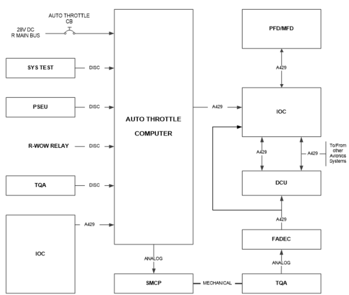
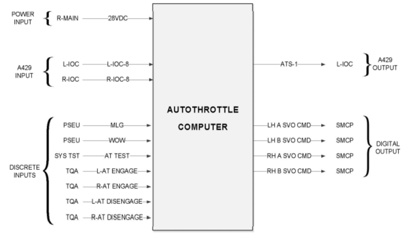
The AT Computer interfaces with aircraft systems via two ARINC 429 IOC-8 Left and Right high-speed input buses, 28VDC input from the aircraft power supply bus plus a total of 7 Open/Ground discrete inputs: WoW, Gear Down, Two AT engage signals, Two AT disconnect signals (from Left and Right TQA levers) and AT initiated system test signal (From the system test panel). The AT Computer also provide four discrete output Pulse Width Modulation (PWM) signals that are used to drive the two SMCP stepper motors. (Each motor requires two phases).
Autothrottle Mode/Status annunciation to the crew and maintenance messages are transmitted via an ARINC 429 ATS-1 bus output to the IOC, and from there distributed to the PFD/MFD, EICAS, MDS and FDR for recording.
Power is supplied to the computer at a nominal 28VDC input from the aircraft power bus.
Cooling of the computer is passive; the heat dissipated internally is removed by convection within the box, then conducted through the aluminum case to the avionics rack air.
05/18/22
Servo Motor Clutch Pack (SMCP)
The dual servo clutch actuator assembly is installed under the centre pedestal in the avionics compartment. It is attached to the under floor structure at FS282.50.
The SMCP is a Line Replaceable Unit (LRU) that includes two independent 2-phase stepper motors driven friction clutches units; each unit is connected to one of two throttle quadrant levers. The Servo Motor Clutch Pack (SMCP) assembly is installed directly under the pedestal, mechanically linked to the aircraft TQA rods.
When the stepper motors are energized, the input power to the SMCP is supplied by the autothrottle computer. The SMCP is a sensor-less unit with no software, current and voltage signals are fully controlled by the AT computer.

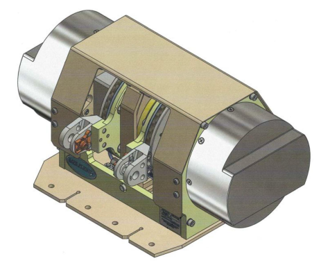
Stepper Motor
The SMCP contains two identical 2-phase stepper motors that provide motive force (via the linkages / control rods) to move the thrust levers of the TQA These motors are connected (via the internal harness, connector, and aircraft harness) to the ATS computer, which provides the 2 phases per motor of PWM excitation. The computer applies a proprietary output to each stepper motor independently. Each stepper motor output is connected to a gearbox to produce smooth motion.
Reduction Gearbox
The gearbox couples the stepper motor output on its outboard side, to a central shaft mounted to the inboard side. The gearbox increases the torque and resolution of the stepper motor output, to a level suitable to drive the output disc, and ultimately the thrust levers.
Shaft
The servo drive shaft transmits torque between the gearhead and the clutch and distributes the TQA control rod load between its end supports.
Clutch and Output Disc
The clutch on each side limits torque transfer between the shaft and output disc. When driving the levers in an active ATS mode, the clutch does not slip; it passes the torque from the shaft to the output disc, moving the linkage and thrust levers of the TQA.
Friction Motor Brake
When the stepper motor is de-energized, the mechanism may be readily backdriven by manually moving the thrust lever, which in turn moves the connecting rod, which rotates the output disc, shaft, gearbox, and stepper motor shaft. A friction brake is mounted to outboard side of the stepper motor shaft to provide a small amount of friction to assist in resisting this rotation.
06/14/22
ATS Control Panel
The ATS is controlled by a centre pedestal mounted ATS control panel. The ATS controls are located on the TQA and on the engine control panel. The TQA contains an ATS engage paddle switch on the aft-side of the throttle lever (each lever has a switch) and the ATS disconnect buttons (trigger finger locations on each throttle handle). The Engine control panel has an Auto Sync knob with three positions: OFF, N1 and N2.
System Interface
The AT Computer interfaces with aircraft systems via two ARINC 429 IOC-8 Left and Right high-speed input buses, 28VDC input from the aircraft power supply bus plus a total of 7 Open/Ground discrete inputs: WoW, Gear Down, Two AT engage signals, two AT disconnect signals (from Left and Right TQA levers) and AT initiated system test signal (From the system test panel). The AT Computer also provide four discrete output Pulse Width Modulation (PWM) signals that are used to drive the two SMCP stepper motors (each motor requires two phases). Autothrottle Mode/Status annunciation to the crew and maintenance messages are transmitted via an ARINC 429 IOC-8 bus output to the IOC, and from there distributed to the PFD/MFD, EICAS, MDS and FDR for recording.
Discretes
AT Computer
The AT Computer receives the following discrete inputs:
- Weight-On-Wheel from R-WOW relay
- Gear down from PSEU
- AT Disconnect SW L from TQA
- AT Disconnect SW R from TQA
- AT Engage SW L from TQA
- AT Engage SW R from TQA
- Test switch from System Test Panel
TQA
Both TQA disconnect switches provide discretes to the DCU. Disconnect information is processed by the DCU (EICAS) logic and provided to the displays to stop the visual annunciations, to the CAS to stop the aural alert and maintenance system for diagnostic (discrete interface check). The AT Disconnect L/R switch needs to be pressed for about 150ms to be considered for its aural cancellation function.
Disconnect information is processed by the DCU (EICAS) logic and provided to the Displays to stop the visual annunciations, to the CAS to stop the aural alert and maintenance system for diagnostic (discrete interface check).
ARINC 429 Interfaces
ATS receives ARINC labels from the avionics and FADEC via the L/R IOC-8 high speed (HS) ARINC 429 data buses. L-IOC-8 provides left engine data via two FADEC channels: LB and LA. R-IOC-8 provides right engine data via two FADEC channels RB and RA.
The AT Computer sends a status word to the Displays (via the L-IOC) on ATS-1 label 270. The Displays send back this label via the IOCs, as a loopback word to ensure a correct communication is established. The ATS disconnects if it does not receive the loopback word for more than 600ms.
The ATS interfaces with avionics systems to provide CAS messages, modes/status and warning annunciations, as well as aural warnings.
AT aural alerts data are managed by the EICAS in the DCU. ATS transmits aural annunciations data on ATS-1 bus. The DCU provides aural alerts to the RIUs.
CAS logic is processed by the DCU (EICAS) and sent to the Displays when a CAS message is set.

System Operation
General Engagement and Disengagement
The AT can be in Engaged and Disengaged/Inhibit state.
When engaged, AT provides arm and active modes typically associated with the Flight Director Vertical Modes:
- Armed: indicates pre-activation state of a mode. An armed mode does not generate any throttle lever movement commands.
- Active: When a mode is Active, the AT generates throttle lever command appropriate for that mode.
The flight crew can Engage the Auto-Throttle via the engage switches and disengage it via the disengage buttons. The ATS test can be initiated though system test panel. The AT operates with All Engine Operative (AEO) and One Engine Inoperative (OEI). The AT active range controls throttles between IDLE position and CLB detent in speed mode and IDLE position to TO detent in thrust mode.
The AT can be manually overridden in which case the AT will disengage automatically.
The AT may be engaged on the ground (in AEO) or in the air when thrust levers are between IDLE and TO detents.
The AT can be re-engaged with one engine inoperative in air. The AT only commands the thrust lever of the operating engine in this condition.
The AT does not engage automatically.
The AT engagement is inhibited in certain conditions. The engage status will flash in yellow for 5 seconds and then is removed.
The AT disengages manually when the AT disconnect button is selected on either thrust lever. The associated aural alert “AUTO THROTTLE” will be heard once and the AT engage status will flash in amber for 2 seconds and then is removed.
The AT disengages automatically in certain conditions. The associated aural alert “AUTO THROTTLE” is heard continuously and the AT engage status will flash in amber continuously until either AT disconnect button is selected.
The Autothrottle system operating modes are mainly dependent upon the currently active FGS Flight Director vertical mode. Engaging the system in air is accomplished by pressing either Engage Paddle on the TQA; if engagement is available, the system will engage, display a green AT in the FMA, as well as the current operating mode (e.g. green SPD). Disconnecting the system normally is accomplished by pressing either disengage push button on the TQA. This will result in momentary flashing amber AT in the FMA, and a momentary aural alert (“AUTOTHROTTLE”). When on-ground, the Autothrottle may only be engaged as part of the normal Takeoff Arm/Engage sequence; it cannot be engaged on-ground in any other mode.
The modes and status annunciations are provided on each MFD.
AT Engagement
AT engagement is manual, AT is armed/engaged in one of the following ways:
- Armed manually (on ground only) by pressing either AT ENGAGE switch
- Engaged manually (on ground) when AT is armed and the thrust levers are moved above 23 degrees TLA
- Engaged manually (in flight) by pressing either AT ENGAGE switch
The AT does not provide automatic engagement (no wake-up feature).
AT Engagement On-ground
On ground, the AT can be armed in takeoff mode (TO) only when either AT ENGAGE switch is selected and the following conditions are true:
- Aircraft on ground (WoW)
- Both engines running
- FD vertical mode is TO
- Both throttle levers below 23 degrees
- Indicated airspeed below 60KIAS
- AT not inhibited (no active AT failures)
When AT is armed in takeoff state, it does not command any thrust lever movement. To engage AT in Takeoff mode (TO), AT must be armed in takeoff mode, both levers are manually advanced above 23-degrees and aircraft speed must be below 60KIAS. When the AT engages in takeoff mode, the thrust levers automatically move to the TO detent and display its mode and status on the FMA.
AT Engagement In-air
AT engagement in air is accomplished by pressing either Left or Right engage switch on the TQA. If system engagement is not inhibited, the AT will engage with an active mode based on the selected vertical Flight Director (FD) mode and display its mode and status on the FMA. If the FD is disengaged with no active failure, the AT engages in its default mode of speed control.
Automatic Disengagement
The AT is disengaged/disarmed in one of the three following ways:
- Manually disengaged/disarmed by pressing either AT DISENGAGE button
- Automatically (disengaged/disarmed) by the AT system (abnormal disengagement)
- Automatically disengaged by the AT system after landing with RETARD mode being active
AT automatically disengages/disarms (abnormal) upon the occurrence of any of the following:
- Engine thrust asymmetric (N1 >35% for at least 2 seconds) or Cross Engine Thrust Mismatch
- Engine thrust N1 is above 96.0 %
- Engine shutdown (from AEO to OEI)
- Engine FADEC Fail (C) indication is set
- Thrust reversers deployed or unsafe indication is set
- AT system internal malfunction
- Input failure when a required input to maintain the AT operation is failed
- Input disagreement fault (including loopback word)
- Aircraft STALL (Stick shaker activation)
- Throttle Levers Manual override or TLA position out of range detected
- AT inhibition state is set from avionic
- FD flag becomes invalid
- FD FLC/VFLC OSPD is detected
- Single Engine approach and FD Go-Around is selected
- Upon landing when WoW is set.
When the AT disengage/disarm manually, a single “Autothrottle” aural alert is heard and visual AT flashing (amber) for 2s will be activated.
When the AT disengage/disarm automatically, a continuous “Autothrottle, Autothrottle” Aural alert and visual AT flashing (amber) will be activated until crew acknowledges the disengagement by selecting either AT disengage pushbutton.
Upon landing, when AT is active in RETARD mode, the AT silently disengages (No cockpit alerts) when Weight-on-Wheels input is set for 0.5 seconds continuously. When landing with AT engaged and not in RETARD active mode, the AT will disengage 0.5 seconds after continuous Weight-on-Wheel and AT alerts will be posted.
Preflight and Takeoff
The Autothrottle system does not require any preflight/daily checks; a self-test is run automatically at aircraft powerup, and a failure is reported with AT FAIL CAS (and additional fault messages which are accessible via the OMS). To arm Takeoff mode (TO in white) requires a number of preconditions, including:
- Both engines running, with N1s matched within 15%
- Flight Director (of the currently active transfer side) Vertical Mode in TO
- Both Thrust Levers below 23 deg (approx.. bottom half of travel)
- CAS below 60 knots.
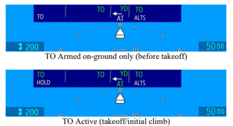
The Autothrottle may be Armed for Takeoff by pressing either Engage paddle on the TQA. When armed for takeoff, TO in white is shown in the FMA. Note that the Flight Director Vertical and Horizontal modes are also “TO”.
Takeoff is initiated by manually advancing both levers. At 23 deg TLA (approx.. mid-range), the Autothrottle will engage, and move the levers to the TO detent. The engagement is annunciated on the FMA with green AT, green TO (and white HOLD), and is also apparent due to the physical motion of the thrust levers by the servos.
AT Operational Modes
The figure below shows typical AT selected active mode per phase of flight from takeoff to landing.

Takeoff
The TAKEOFF (TO) mode is armed by pressing either AT ENGAGE switch on the TQA under the following conditions:
- AT engagement status is not inhibited,
- Aircraft on ground and both engines are running,
- The FD vertical mode is TO,
- Throttle levers are below 23 degrees and
- Airspeed is below 60 KIAS.
The TAKEOFF (TO) mode activates when the throttle levers are manually advanced above 23 degrees. Once activated, the AT engages and energizes both servomotors to automatically moves the thrust levers to the takeoff detent within 3.5 seconds. This is to be ahead of the FADEC takeoff thrust schedule to maintain the required takeoff thrust performance. The FMA shows TO and AT armed (white) and TO active and AT engaged (green).
Hold
HOLD mode is armed after TAKEOFF mode becomes active on ground. The HOLD mode activates and TO mode reverts to armed when the airspeed reaches 60 KIAS and throttle levers are at the takeoff detent. When HOLD mode is active, the servomotors are de-energized to prevent inadvertent lever command movement from the takeoff detent (safety). At any time, the throttle levers can always be overridden by the crews.
The AT captures the pressure altitude on the runway at 60 KIAS and maintain HOLD mode until 400 feet above the captured altitude. Upon reaching 400ft above the captured altitude, the AT will re-energize the servos and transition from HOLD to the selected armed mode. If the active FD vertical mode remains in TO, the AT transitions to TO mode and keep the levers in the TO detent.
If the active FD vertical mode is changed prior reaching the 400ft, the Autothrottle will transition to either THRUST or SPD and adjust the levers position accordingly. If a Takeoff is performed without the use of Autothrottle, the Autothrottle cannot be engaged until above 400ft AGL. (An attempt to do so will result in the engagement inhibit warning).
To exit HOLD mode, the AT must receive the current pressure altitude values lower that the pre-selected altitude. (i.e. aircraft is in climb). If current pressure altitude is higher than the pre-selected altitude (i.e. aircraft is in descent) the AT will maintain the HOLD mode until pre- selected altitude will change or AT will manually be disengaged.

Mode transition at 400’
Upon reaching 400’, the system will transition out of Takeoff Hold to the mode previously shown in the armed field. If no FGS Vertical Mode changes were made, the FD Vertical Mode would still be in TO, and the Autothrottle would transition to green TO, which will re-energize the servos, but keep the levers in the TO detent. If a mode change had been made, then at 400’ the Autothrottle would transition, e.g. to THRUST or SPD. If a Takeoff is performed without the use of Autothrottle, the Autothrottle cannot be engaged until after climbing above 400’. (An attempt to do so would result in the engagement inhibit warning)
Climb (THRUST)
The climb THRUST mode is activated when FLC/VFLC FD vertical mode is active, pressure altitude is higher than 400 feet above the pressure altitude captured at 60 KIAS on ground, and the preselected altitude is higher than the actual baro altitude. When climb THRUST mode is active, the AT commands the throttle levers towards the Climb Detent. When THRUST mode is active, the aircraft target speed is maintained by the autopilot or by the crew by following the FD vertical guidance command. Upon Altitude Capture, the Autothrottle will transition to SPEED mode.

Speed Mode (SPD)
The SPEED mode is activated when one of the following FD vertical modes is active:
- Altitude Select (ALTS, VALTS, ALTV, VALTV)
- Altitude Capture (ALTS CAP, VALTS CAP, ALTV CAP, VALTV CAP)
- Altitude Hold (ALT, VALT)
- Vertical Speed (VS, VVS)
- Vertical Path (VPATH)
- Vertical Glide Path (VGP/GP)
- Glide Slope (GS)
- Pitch Angle (PTCH, VPTCH)
If the AT is engaged with the FD OFF, and the validity of FD input indicated “Valid”, the AT will default to speed mode. When SPEED mode is active, the AT commands the throttle levers between the IDLE and CLIMB FLAT position to track and maintain within +/-3 KIAS or +/- 0.01 Mach the selected (IAS / Mach) speed bug. The speed bug reference is selected either by the crew using the SPEED knob on the FGP or from FMS VNAV planned reference speed.
The AT will track either IAS or Mach airspeed, change between IAS and Mach does not affect speed tracking.
The speed mode is not limited to N1 Maximum Cruise rating and will use the optimal required thrust to achieve and maintain the selected airspeed. When the aircraft is flying under turbulence condition, the AT speed tracking may momentarily exceed the defined tolerance, however the AT will correct the speed error and bring it within the speed tolerance.

Thrust Limit (LIM in Speed Mode)
Speed mode contains a ‘Thrust Limit’ annunciation function to warn if the available thrust authority is insufficient to maintain the selected airspeed target. If the Autothrottle has reached the maximum thrust it is permitted to command, and the current speed is decreasing, and is more than 10 knots/0.03M below the target speed, then flashing amber LIM will be posted on the FMA. This may occur, for example, if an excessive VS climb rate is set on the FGS and insufficient thrust is available to maintain the airspeed target.
Overspeed (OSPD in Speed Mode)
In SPD mode, the AT activates OVERSPEED mode when the airspeed is 3 KIAS / 0.01 Mach above maximum operating airspeed (VMO)/Mach (MMO) for 1 second continuously.
When AT Overspeed mode is active, the AT retards the throttle levers toward IDLE position. The OVERSPEED mode will reverts back to SPD mode when the speed decreases 3 KIAS / 0.01 Mach below the maximum operating airspeed / Mach.
The maximum operating speed is computed by the ADC and transmitted to the PFDs to drive the high-speed tape awareness (red tape) on the airspeed/Mach tape. The value of the maximum operating speed (VMO/MMO) is a function of aircraft data and flight condition. Extending the gear or flap above their respective speed threshold will trigger the autothrottle overspeed.
When the aircraft overspeed cause the FD vertical mode to enter to FLC OSPD, the AT will disengage and will be inhibited for re-engagement while the condition exist. The AT overspeed function is active only when the AT is active in SPD mode.

Descent (THRUST)
The descent THRUST mode is activated when FLC/VFLC FD vertical mode is active and the preselected altitude is lower than the actual baro altitude. When descent THRUST mode is active, the AT commands the throttle levers towards IDLE, THRUST (green) indication is displayed and white SPD will be shown as the armed mode if Altitude Capture is armed. Aircraft target speed is maintained by the Autopilot or the flight crew by following the FD vertical guidance (i.e. using elevator). Upon altitude capture, the Autothrottle will transition back to SPD mode.
Limit Alert
In SPD mode, the AT activates Limit Alert “LIM” when the AT is unable to maintain the required speed target due to thrust limitation. The thrust limit alert is active when the AT has reached the maximum thrust permitted (TLA at Climb Flat) and the current airspeed is 10 KIAS / 0.03 Mach below the speed target and the airspeed rate of change (acceleration) is less or equal to +0.1 KIAS/sec or 0.0003 Mach/sec for more than 3.0 seconds continuously, or when the airspeed is 10 KIAS / 0.03 Mach above the speed target, TLA is at the IDLE position and the airspeed rate of change (deceleration) is greater than or equal to -0.1 KIAS/sec or -0.0003 Mach/sec for more than 3.0 seconds continuously. The AT deactivates the thrust limit alert when the speed is within 10 KIAS / 0.03 M of the selected speed target IAS / Mach.

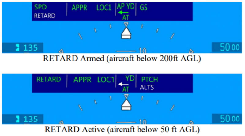
Retard (RETARD)
The AT includes function to retard the thrust levers to IDLE during the landing flare and automatically disengage silently after landing (with no visual or aural alerts). RETARD mode is armed if the following prerequisite conditions are met:
- Gear Down
- Flaps Valid and greater 28 degrees
- Radio Altitude Valid and transition through 200 ft (AGL)
- AT Engaged with speed mode (SPD) active
- Speed reference selected as IAS
- AT RETARD INHIBIT (C) CAS message not posted (see below)
- Steep Approach not selected
The AT activates RETARD mode and automatically reduces the throttle levers towards IDLE position when the aircraft descends below 50ft AGL. The AT automatically disengages 0.5 second after aircraft touchdown with no aural and visual alert, upon disengagement, the servos are de-energized, which eases subsequent manual control of the thrust levers. if the required conditions are not met for the retard mode, the AT remains in speed mode, disengages 0.5 second after aircraft touchdown and will trigger an aural and visual alert. When RETARD mode is active, the AT allows mode transition only to Go-Around (GA) if the FD GA vertical mode is selected.
RETARD mode includes several monitors intended to mitigate risks for safety reasons and provide availability until touchdown, the retard mode is inhibited, disarmed (if previously armed) and AT RETARD INHIBIT (C) CAS message is posted if one of the following condition is detected; abnormal fluctuation of radio altitude, input failure (flaps or radio altitude), aircraft not configured for landing (gear, flaps position). The AT RETARD INHIBIT (C) CAS message is latched by the AT computer and will only be reset if GA is selected, or AT disengages (Manually or automatically). When RETARD is armed, climbing above 200ft Radio Altitude for more than 1s will disarm RETARD (and clear the white RETARD annunciation in the armed field of the FMA). Because these conditions can occur due to uneven terrain, it is not considered a failure or abnormal event, and will not cause the AT RETARD INHIBIT (C) CAS to post. The RETARD may be re-armed by descending again below 200ft Radio Altitude (as long as all the other RETARD Arming criteria, above, are still met.) Note: RAD ALT SSM set to NCD is not considered as RAD ALT fault.
Go Around (GA)
When both engines are running, and the FD vertical mode is in GA (TOGA is selected by the crew), the AT Go-Around (GA) Thrust mode is activated and the thrust levers are commanded to the takeoff detent, (within 4.5 seconds).
With AT active in GA, and the crew selects any other vertical mode than FD GA, the AT will transition to the active FD mode even if the levers have not yet reached the takeoff detent.
When TO/GA is selected by the crew below 200 ft AGL, the AT RETARD INHIBIT (A) CAS message is inhibited until above 250 ft AGL or flap retraction to less than 28 degrees. When aircraft altitude is below 200 ft AGL, following TO/GA selection, if the crew changes FD vertical mode to Pitch and retract landing and/or flaps, the AT transitions to SPD which will result in AT RETARD INHIBIT (C) CAS. Special AT logic was developed to prevent that nuisance from being posted until above 250 ft AGL or Flap position transition from 30 to 20 degrees.
During single engine approach with AT engaged, if the FD mode changes to Go Around, The AT will automatically disengage and post continuous cockpit alerts (Aural and visual) until crew acknowledge by selecting either disengage button. The AT can be re-engaged in OEI after automatic disengagement. Refer to AFM limitation and procedure.
In OEI, the FADEC will command engine rating to Automatic Power Reserve (APR) when the thrust lever in TO detent.
While AT GA is active, if the crew selects any vertical FD mode other than GA, the thrust levers will retard from takeoff detent, APR thrust will no longer be available. In order to maintain aircraft performance while in OEI GA, the AT disengages to allow the flight crew to manually maintain the required climb performance. Refer to AFM single engine operating limitation for AT re-engagement in OEI GA.

Controls and Indications
Controls
The Autothrottle engage/disengage is controlled by the crew via the following cockpit switches:
- Two AT ENGAGE switches located on the thrust levers.
- Two AT DISENGAGE buttons located on the thrust levers.
The AT Engage/Disengage momentary switches are used for manual engagement or disengagement of the Autothrottle (use of either lever side switch is sufficient).
AT system can be armed/engaged, disengaged or inhibited from engagement. When engaged the AT is ready to generate throttle lever command. The throttle levers can be overridden by the crew at any time while AT is engaged and will result in automatic disengagement with the crew alerts related to abnormal disengagement. When the AT is disengaged, the servomotors are de-energized and the throttle levers are fully controlled by the crew.
AT engagement is manual, AT is armed/engaged in one of the following ways:
- Armed manually (on ground only) by pressing either AT ENGAGE switch
- Engaged manually (on ground) when AT is armed and the thrust levers are moved above 23 degrees TLA
- Engaged manually (in flight) by pressing either AT ENGAGE switch
The AT does not provide automatic engagement (no wake-up feature).
Indications
Autothrottle visual mode/status and crew alert annunciations are indicated via the Flight Mode Annunciator (FMA) on the Primary Flight Displays (PFDs), and via Crew Alerting System (CAS) messages on the EICAS window, while aural annunciations are provided through the cockpit-installed audio system, via the Radio Interface Unit (RIU). Additionally, the autothrottle provides maintenance indications to the Maintenance Diagnostic Computer (MDC) displayed on maintenance/diagnostic pages.
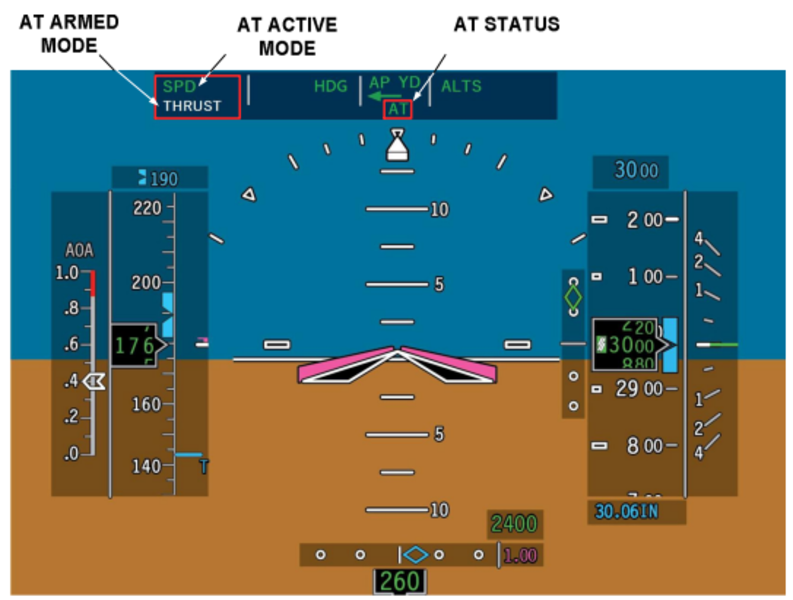
The AT engagement status, armed and active mode annunciations are displayed on the PFD’s Flight Mode Annunciator (FMA). The active mode is indicated on the top left side of FMA. The AT armed mode is indicated on the bottom left side of FMA. The AT engagement status is indicated in the center of the FMA below the flight guidance AP/YD mode status.
AT Mode Field
The AT mode field on the PFD is split into the active mode field and the armed mode field. The active mode is the upper field, and the armed mode is the lower field.
- The AT mode field shows the AT mode that is currently selected for the AFCS. When armed, the applicable mode (TO, HOLD, SPD, RETARD, THRUST) shows white in the AT armed mode field and (TO, HOLD, SPD, RETARD, THRUST, GA) shows green on the AT mode field. All active AT modes flash for 5 seconds when they first come into view, then remain steady.
- Once the AT mode is engaged, the AT mode shows in green in the AT active mode field, and the AT armed mode message is removed.
Autothrottle Engagement Status Field
When the ATS option is enabled, the XFR arrow is repositioned upward and the AT Engagement Status Field occupies the XFR arrow space in the center of the Flight Mode Annunciator (FMA) of the PFD. The AT Engagement Status Field messages and functions are as follows:
- AT – Green/White/Yellow
- When the autothrottle is engaged, AT shows in green in the AT Engagement Status Field . AT shows in white when the autothrottle is TO armed. AT shows in yellow when the autothrottle is disengaged manually or automatically.
- When the autothrottle is disconnected manually, AT turns yellow and flashes for 2 seconds, then blank. When the autopilot is disconnected automatically, AT turns yellow and flashes continuously until the alert is cancelled. The AT disconnect alert is retained until the CAS logic for DCU AT DISCONNECT is set. The AT cannot be reengaged until the DCU AT DISCONNECT is set.
- A manual AT disconnect is accompanied by a single AUTOTHROTTLE voice aural. An automatic AT disconnect is accompanied by a continuous AUTOTHROTTLE, AUTOTHROTTLE voice aural.
Refer to the tables below for details of the mode and status annunciations.
| AT Status | Color | Description | Flashing |
|---|---|---|---|
| - | AT is disarmed/disengaged | - | |
| AT | White | AT is armed with TO mode armed (on ground only) | None (steady) |
| AT | Green | AT is engaged with an active AT mode | None (steady) |
| AT | Amber | AT manual disarm/disengage | Flashes for 2s then blank |
| AT | Amber | AT automatic disarm/disengage or AT engagement is inhibited and either engage switch is pressed | Flashes continuously |
| Active Mode | Color | Description | Flashing |
|---|---|---|---|
| - | No AT active mode selected | - | |
| TO | Green | Takeoff mode active | Flashes for 5s then steady |
| HOLD | Green | Hold mode active | Flashes for 5s then steady |
| THRUST | Green | Thrust mode active | Flashes for 5s then steady |
| RETARD | Green | Retard mode active | Flashes for 5s then steady |
| GA | Green | Go Around mode active | Flashes for 5s then steady |
| SPD | Green | Airspeed or Mach control | Flashes for 5s then steady |
| OSPD | Amber | Overspeed mode active | Flashes continuously |
| LIM | Amber | Limit alert active | Flashes continuously |
| AT Arm Mode | Color | Description | Flashing |
|---|---|---|---|
| - | No AT mode armed | - | |
| TO | White | Takeoff mode armed | None (steady) |
| HOLD | White | Hold mode armed | None (steady) |
| THRUST | White | Thrust mode armed | None (steady) |
| RETARD | White | Retard mode armed | None (steady) |
All transitions from armed to active mode are annunciated by momentarily flashing of the new mode then becoming steady. Only one active and one armed mode can be displayed at the same time. Manual AT disengagement results in AT disengagement caution (AT status flashing amber) provided for 2 seconds and subsequently cleared without any additional crew input. If the AT disengages/disarms automatically, or if the avionic loses communication from the AT computer, or AT engagement is inhibited and either engage switch is pressed, the AT disengagement caution (AT status flashing amber) is posted continuously, for at least 2 seconds, and can be cleared only once acknowledged by the crew via any one of the TQA’s AT Disengage switches. When the AT is disengaged all AT related fields on the FMA are cleared. There is no visual annunciation provided after automatic disengagement upon landing following AT being in RETARD active mode.
The AT disengagement visual annunciation is associated with an aural annunciation that is aligned with the visual annunciation.
Maintenance Indications
The AT computer is capable to diagnose a failure condition either related to internal system failures or aircraft inputs that prevent AT from operating normally. When AT detects the failure, it transmits the information via the AT ARINC IOC output bus to the MDC to be recorded and displayed with the time stamp and date of the failure.
The AT is also recording in the internal AT NVM memory reasons of AT disengagement and Retard inhibit which occur while the aircraft is in air for the current flight leg and the previous consecutive five flight legs. The faults recorded during the flight are sent to the MDC and available for display on the Avionics Fault Page of the MDC.
In addition, the AT is also sending status of AT discrete input, details of internal AT system faults, and operation status (such as FADEC Channel in control, OEI/AEO mode, Servo motors energized, ADC/IRS, XFR side selection etc.). This information is not recorded on the MDC and is only used to show real time input status for troubleshooting purpose.
The following are ARINC 429 outputs to the MDC:
- AT Fault Message Word
- AT Maintenance – Discrete
- AT Maintenance – System State
- AT Maintenance – ARINC 429
- AT Current/Last Leg NVM
- AT 5-Legs NVM
System Test
The ATS implements Built-In-Test (BIT) function. The AT computer performs automatic power-up test (PBIT), continuous test monitoring of fault during operation (CBIT) and manually initiated self and servo tests on ground (IBIT).
Power-Up Built-In Tests (PBIT)
Upon application of power or a power cycle, the computer software performs system initializations (clearing variables and counters, setting registers, etc.) and executes several test functions.
The power-up test is executed regardless of whether the system is on ground or in air and take less than 20ms to complete. During the PBIT on ground, the AT computer executes the power-up test and wait for 3 seconds to confirm wow status, the AT enter cold start state and continue additional testing which includes energizing the servos briefly to check if that causes a fault and begins monitoring inputs and computing the fault logic which takes 8 seconds to perform.
During the PBIT in air, the AT will immediately monitor the ARINC 429 input data and start the power-up test, the AT enter cold state and wait for 3 seconds to confirm W-off-W status, ARINC data transmission is disabled and resumes 3 seconds after initial application of power, once the test is completed successfully, the AT can be engaged in any operational mode.
Upon successful completion of the test, the AT becomes fully operational. If the test fails, a (latching) fault determination will be made. The main state-machine program will attempt to execute but will only post AT FAIL (A) CAS message and AT INTERNAL FAULT on the maintenance diagnostic menu, and the system cannot be engaged. If communication with avionics cannot be established, the avionics will post AT FAIL (A) CAS (due to no data reception from the AT computer).
While AT is engaged, and communication with avionic is lost for longer than 1s, the avionic will trigger AT disengagement alert.
Continuous Built-In Tests (CBIT)
During normal operation, the following tests/monitors list, but is not limited to, are performed continuously regardless of the state of the computer.
- Voltage Monitors (+15V, +5V, and Motor Voltage) are polled for low voltage condition
- Watchdog: monitor the program execution, if failure is detected, the system reset the processor restarting the program.
- RAM ″heartbeat" test at periodic interval read/write operation.
- Serial Bus Faults monitor processor serial buses communication
- Interface devices (ARINC Transceivers and Discrete Input are polled for Faults)
- ARINC 429 Input hardware/software validation ω ARINC 429 Special Input Consideration validation
- Discrete inputs are monitored for a stuck switch
- A ″Loopback" test (verifies ARINC 429 communication with avionics)
- Flight Director Mode Ambiguity
Certain faults are only detectable when the servos are energized, and so the associated monitors are only active when the servos are being driven (AT engaged):
- Motor Drivers are polled for faults (over-temperature, or over-current)
- Motor Current monitors are polled for a low-current condition
- Override is polled for the estimated vs received of each levers position
When the system is engaged, detection of the faults (considering some nominal persistence/debounce) will cause automatic disconnect with a warning annunciation. When the system is armed, detection of the faults (considering some nominal persistence/debounce) will cause automatic disarm with a warning annunciation.
Initiated Built-In Tests (IBIT)
The Autothrottle includes two manually IBIT features - Self-Test of the AT Computer - Servo-Test of the AT Servomotors. The Self-Test is used for maintenance purposes, and or for Return To Service test (RTS) upon LRU replacement of the AT Computer or the Servomotors (SMCP), or performed by the crew as required.
IBIT can be initiated on ground by selecting AUTO THROTTLE on the system test panel.

Initiated AT Computer Self-Test
The computer self-test runs when the aircraft is on ground, the AT is disarmed/disengaged and no failures is reported. Self-test is inhibited in air. The computer self-test is manually initiated by rotating the selector knob on the SYSTEM TEST PANEL to AUTO THROTTLE position. The selector knob PUSH TO TEST needs to be pressed and hold for minimum of 0.2 seconds. During the initiated self-test, the system is briefly activating the component of the Autothrottle system checking the servo motor connection to the computer (aircraft wiring and internal motor windings continuity), and the computer servo current drivers. The Initiated Self-Test runs for approximately 15 seconds to allow sufficient time to initiate Servo-Test, the AT IN TEST (S) CAS message is posted for that duration then cleared upon completion.
In the event of self-test failure, the AT FAIL (A) CAS message and AT SELF TEST FAULT maintenance message(s) are posted. The AT computer will latch the fault until initiated self-test is repeated and pass successfully or AT computer power cycle is performed. Attempt to engage the AT under active fault condition is inhibited. During the Self-Test, manually moving the levers has no effect on the ATS self-test process.
Initiate Servo Self-Test
The Servo test is a maintenance function that serves to verify that the thrust levers feedback control system is working properly including the TQA RVDTs/ FADEC which provide feedback of the TLA∝s angle to the AT computer. It is intended also to verify that the levers are moving freely (no mechanical jam or rod disconnect) between IDLE position and Takeoff detent and can overcome the detent force (Climb/Takefoff). This test is intended to be performed after SMCP/TQA LRU installation / replacement, or at crew discretion. Note that the Servo test is only checking the throttle levers of the AT operational range between IDLE and takeoff, and does not verify the TQA levers in APR position nor the reverse range (thrust reversers).
To initiate a Servo-Test, the levers should be first be placed (manually) in the TO detent with both engines not running. A manual initiated Self-Test need to be activated by pressing the selector on the System Test Panel pointing to the Auto Throttle position.
While Self-Test is running the AT IN TEST (S) is posted, either AT engage switch is pushed momentarily to start the Servo-Test. If the Servo test is not initiated within the 15 seconds window of being in Self-Test, the servo test cannot be initiated. While Servo-Test is running both AT IN TEST (S) and AT SERVO TEST (S) CAS messages are posted during the entire servo test duration (approx. 20 seconds) then both cleared at the completion of the test.
When the servo test start, the servos will then both levers move aft, then forward, then one at a time move aft back to IDLE. The TLA movements are timed and need to complete the full travel range between IDLE and Takeoff detent within 4 seconds plus 1 second position verification time while in IDLE and takeoff. The total test completion time is about 20 seconds. AT SERVO TEST (S) CAS message will be posted for that duration then cleared upon completion.
In the event of servo test failure (that could occur if the levers did not reach their expected TLA position on time due to jamming, rod disconnect conditions, or servo current fault detection), the AT will latch the fault, AT FAIL (A) CAS message and related maintenance message(s) are posted.
While Servo-test fault is latched, the AT is inhibiting AT engagement in any mode or arming AT in takeoff. To clear the latched fault, the Servo test need to be reinitiated and pass successfully, or AT computer power cycle to be performed.
05/19/22
System Monitoring
The ATS detects, reports, and responds different fault conditions. The reports include visible indicators on the Multi-Function Displays (MFDs) which show the ATS engagement status and ATS active and arm modes, and the Crew Alerting System (CAS) messages, aural alerts, and maintenance messages. Responses include mode changes, limitations, and inhibitions, and in some cases, disengagement.
The ATS performs monitoring functions of the hardware and software as required to ensure system safety and availability. The monitor functionality includes fault detection scheme at the component and system level and corrective action.
The AT computer contains several components monitors that continuously check the health and conditions within the defined tolerances (threshold values, persistency times..etc). The main implemented component monitors affecting availability, safety and functionality are, but is not limited to, the following monitors:
- Motor Current Monitor for each motor driver coil phase (LA, LB, RA, RB)
- Motor Voltage Monitor
- Power Supply Voltage Monitor (+15V, +5V)
- Discrete Input Monitor
- ARINC 429 Input validity and reasonableness Monitor
- Aircraft data parameter Monitor (FD ambiguity, AC configuration...)
- Throttle Levers Override Monitor
- ARINC 429 loopback interface check
- ARINC 429 Special Consideration - RADALT
- ARINC 429 Special Consideration - FLAPS
- ARINC 429 Special Consideration - Preselected ALT
- ARINC 429 Special Consideration - Baro-Corrected ALT
- ARINC 429 Special Consideration - SPC_SSM (on ground SSM FT does not cause AT FAIL (A) CAS message if AT is not armed or engaged) If the monitor trips causing a system disengagement, cockpit indication is annunciated to the crew and related maintenance indication(s) are generated in an appropriate time frame.
System Maintenance Diagnostic
The ATS provides diagnostic data via the ARINC 429 output bus to the aircraft maintenance system data reader which allows maintenance personnel to review status of AT mode of operation, real time signals of input discrete system status, AT internal system failures, ARINC 429 input failures, and NVM recorded events.
The AT records into its internal NVM memory the cause of AT disengagement and retard inhibit which occur while the aircraft is in-air for the current flight leg and the previous flight consecutive flight legs.
In flight, all events are recorded for the current leg and remain latched until the next flight leg (transition from on-ground to in air), upon takeoff, all previous event of the last flight leg are recorded and latched for 5 consecutive flights before it start being overridden by new faults. This feature is to account for possibility that the aircraft may not be at a suitable maintenance facility when AT failure occurs. The AT does not record failures on ground.
CAS Messages
The caution AT RETARD INHIBIT CAS message is displayed to indicate to the crew that RETARD mode is not available for landing. The RETARD mode will not arm or activate if a required input has failed and/or landing configuration, Flaps 30 and Gears Down, is not set. The AT RETARD INHIBIT caution message shows on the EICAS along with a single chime aural alert. When it is posted and the crew decide to continu the approach, they must disengage the AT before landing and manually control the thrust lever.
The advisory AT FAIL CAS message is displayed when an internal system failure, input failure, self-test or servo-test failure is detected. The AT FAIL CAS message and the associated maintenance message is generated by the AT Computer to report the cause of the failure, the system disengages (if previously engaged) and AT engagement will be inhibited. The AT FAIL CAS message is latched in the event of a Self-Test or Servo-Test is failed. For other failures, when the failure is no longer present, the AT FAIL will clear. The AT FAIL CAS message is also posted by the avionic when communication between the AT system and avionic is lost.
The status AT IN TEST (S) CAS message is displayed when the ATS is running the initiated self-test of the AT Computer.
The status AT SERVO TEST (S) CAS message is displayed when the ATS is running the initiated servo-test of servomotors SMCP.
Aural Alerts
The following Autothrottle aural alerts are issued through the cockpit-installed audio system via the Radio Interface Unit (RIU).
Single “Autothrottle” aural alert is annunciated when a manual AT disarm/ disengage occurs.
Continuous “Autothrottle, Autothrottle” aural alert (string of two consecutives “Autothrottle”) is annunciated in any of the following cases.
- Automatic AT disarm/disengage (except after landing with RETARD mode as active mode), or
- AT engagement is inhibited and either engage switch is pressed, or
- Loss of communication between AT computer and avionic when AT was previously engaged or AT aural was previously set.
The continuous aural alert can be cleared upon crew acknowledgement by pressing either AT disengage button as required. The activation, deactivation, and prioritization of Aural Alerts are asserted by the Crew Alert Logic function.