


04/26/21
Overview
Note:
The dual HF communication system installation is available via optional SB 350-23-001.
The HF communication system (option) contains two HF transceivers with their related antenna systems. The HF communication systems supplies long-range, air-to-ground, and air-to-air voice communications. The system has 280,000 communication channels that are usually tuned at 100 Hz increments from 2.00 to 29.99 MHz.
Also, the HF transceivers can supply audio signals that can be examined for selective calling (SELCAL) code by the optional SELCAL system.
A control display unit (CDU), or the multi-function displays (MFD), tune the HF transceivers.
The HF communication system uses an HF antenna which is integral to the vertical stabilizer.
03/13/18
HF Transceiver
The HF transceiver is a multichannel HF voice-transmitter/receiver. There are two HF transceivers installed in the aft equipment compartment: HF transceiver No. 1 and HF transceiver No. 2. The transceiver front panel has a handle to help remove the transceiver from its mounting tray. In usual condition, the pilot CDU tunes the HF transceiver No. 1 and the copilot CDU tunes the HF transceiver No. 2.
The HF transceiver supplies long-range 2-ways amplitude-modulation (AM) voice communications. The transceiver can operate in simplex (SIMP) or half-duplex (DUP) mode and, as applicable, can be set to the AM, upper side voice (UV) or lower side voice (LV) operation mode. If necessary, the system can be tuned to the international telecommunications union (ITU) frequencies, with the use of maritime (MAR) frequencies channel-numbers.
When a radio interface unit (RIU) compatible with SELCAL system (option) is installed, audio inputs from the HF transceiver are examined for SELCAL code (VHF transceivers find and send SELCAL code directly to the RIUs). The RIU supplies SELCAL messages to the crew, when the SELCAL code is the same as the code given to the aircraft.
Each of the transceivers contains a power amplifier module, an aeronautical radio incorporated (ARINC) 429 interface module, and a card cage. The card cage contains the receiver, exciter, processor, synthesizer, and power supply cards.
The processor controls all the functions of the transceiver unit and monitors for fault condition detection. It also controls and monitors the coupler with fiber-optic cables.
The HF transceivers get power from a 28 VDC electrical source as follows:
- The HF transceiver No. 1 gets 28 VDC power from the L MAIN BUS, through a relay (in the left dc power-center (LDCPC)) controlled through circuit breaker CB1-B3 (on the left circuit-breaker panel).
- The HF transceiver No. 2 gets 28 VDC power from the R MAIN BUS, through a relay (in the right dc power-center (RDCPC)) controlled through circuit breaker CB2-B3 (on the right circuit-breaker panel).


HF Transceiver Mounting Tray
The HF communication system has two HF transceiver mounting trays. There is one tray for each HF transceiver: HF transceiver mounting tray No. 1 and HF transceiver mounting tray No. 2. The two HF transceiver mounting trays are installed in the aft equipment compartment, in the locations that follow:
- HF transceiver mounting tray No. 1 is installed at FS801.12, WL91.41, and RBL15.00
- HF transceiver mounting tray No. 2 is installed at FS764.22, WL76.78, and RBL3.00.
Each HF transceiver attaches to its HF transceiver mounting tray. Two hold-down clamps on the tray engage the hold-down hooks on the transceiver and attach it to the tray.

12/06/19
HF Antenna Coupler
There are two antenna couplers: HF1 antenna coupler and HF2 antenna coupler.
The antenna couplers are installed in the vertical stabilizer at FS784.61. The coupler front panels have handles to help remove the couplers from the tray.
The antenna couplers change the antenna impedance to 50 Ω. This causes the impedance of the power amplifier to be the same, which lets maximum power go to the antenna. Vacuum relays tune the antenna couplers. The antenna couplers set the radio frequency (RF) coils and capacitors, in or out of circuits, to get the necessary impedance at the set frequency.
The HF antenna couplers get power from a 28 VDC electrical source as follows:
- The HF1 antenna coupler gets 28 VDC power from the L MAIN BUS, through circuit breaker CB5-A1, in the LDCPC
- The HF2 antenna coupler gets 28 VDC power from the R MAIN BUS, through circuit breaker CB6-A1, in the RDCPC.

12/06/19
HF Antenna-Coupler Pressure Gauge
Note:
On A/C ALL Post SB 350-23-001 Basic or Rev 1 and Pre SB 350-23-001 Rev 02, Rev 3 or Rev 4 or Pre SB 350-23-014
The HF antenna couplers are pressurized to 6 psi with nitrogen or dry air to prevent electrical arcing. The pressure of each coupler can be read on pressure gauges installed in the aft equipment compartment between FS740.30 and 756.25 at stringer 14. The pressure gauges have a graduation from 0 to 15 psi.
The forward HF antenna-coupler pressure gauge shows the indication of the HF1 antenna coupler.
The aft HF antenna-coupler pressure gauge shows the indication of the HF2 antenna coupler.

HF Antenna-Coupler Mounting Tray
The HF communication system has only one HF antenna-coupler mounting tray. The HF antenna-coupler mounting tray is in the ram air fairing on the vertical stabilizer. The HF antenna couplers attach to the HF antenna-coupler mounting tray. The connector at the rear of the tray supplies the interface from the couplers to the HF antenna feedline. Hold-down clamps on the tray, engage the hold-down hooks on the antenna couplers, and attach the couplers to the tray.

HF Antenna Feedline
The HF communication system has one HF antenna feedline. The HF antenna feedline connects the HF antenna-coupler mounting tray to the HF antenna.

HF Antenna
The HF antenna is an integral part of the leading edge of the vertical stabilizer. It is located between FS783.75 and FS826.00.

System Operation
Theory of Operation
Transceiver Functions
The HF transceiver is the primary component of the HF communication system. The transceiver is an automatically tuned multi-channel unit that receives the tune data on the data busses from the CDUs and the RIUs.
The HF transceiver is made for continuous or standby operation in the receive mode and in the transmit mode (except under thermal stress conditions).
The HF processor uses a software to supply the primary functions that follow:
- System initialization (power-up and loading of initial parameters)
- Operation functions (transmit, receive, or standby operation)
- Built-in test function
- Fault condition detection
- Channel presets functions
- Process functions for the control inputs (selection inputs for frequency, transmission, or emission modes; control inputs for squelch level, volume level, and power level).
Tune data entered by the operator is kept by the microprocessor memory and used to reduce future tune times. The transceiver can keep 99 preset channels in its non-volatile memory (NVM).
The HF analog audio output is routed from the HF transceiver to the RIU where it is changed to a digital signal and sent to the control panel electronics (CPE).
The audio from the pilots microphone is routed through the CPE and sent digitally to the RIU where it is changed to analog and sent to the HF transceiver.
The HF communication system has different tune and control command routes. Radio tune reversion and display reversion give different modes to tune the HF transceivers.
Selective Calling
The selective calling (SELCAL) function is a notification function that is done by a ground operator that sends a SELCAL code, tone pulses, and the airborne receiver/decoder. The receiver/decoder automatically monitors HF frequency signals for the unique SECAL code. When the SELCAL code is detected, the flight crew is notified with an aural message and crew alerting system (CAS) message. The HF transceiver must be manually tuned. When the pilot or copilot keys the radio for the SELCAL code, the SELCAL message is acknowledged and the CAS message is removed.
RIU
When the aircraft receives a SELCAL code message, the RIU sends an input to the data concentrator unit (DCU). The DCU then shows the CAS message (advisory) on the MFD and sends an input to the RIU to play the aural alert. The RIU removes the notification of the SELCAL to the DCU when the mic is keyed for the HF radio.
Tune Modes
When a radio tuner (MFD or CDU) sends a tune or control command to its target radio, it also sends that signal to all radio tuners. It does this so that the radio tuners are all synchronized. A radio tuner sends a tune and control command when the frequency or channel is set.
The radio tuners each monitor correct radio tune signals and controls, as much as possible. The radio tuner compares its tune command with its radio echo. It does this when a radio tuner does a local tune or receives a tune command from a different radio. It compares them for no longer than 3 seconds.
If the radio echo is not the same as the tune command in less than 3 seconds, the active frequency display changes color. A local tune command overrides a remote tune command.
Tune Reversion
The TUNE reversion switch, on the reversion select panel (RSP), is a switch that makes specified tuners serviceable. In normal operation mode (TUNE reversion switch on the RSP set to NORM position), each MFD tunes its same-side HF radios through the RIU. Tune commands from the opposite-side MFD or CDU are received by the same-side MFD and transmitted to the applicable radio through the RIU. A fail condition of the same-side MFD, makes the opposite-side MFD the primary tuner.
In MFD ONLY mode (TUNE reversion switch on the RSP set to MFD ONLY position), the CDUs do not tune the HF transceivers. The MFDs ignore signals from the CDU, if it tries to tune the HF transceivers. In MFD ONLY mode, the MFD tunes the HF transceivers as in normal operation.
In CDU ONLY mode (TUNE reversion switch on the RSP set to CDU ONLY position), the MFDs cannot tune the HF transceivers, and the CDUs tune the HF transceivers directly. When the CDU tunes the HF transceivers in CDU ONLY mode, the CDU tune signal goes directly to the HF transceivers. CDU ONLY mode is usually for pre-departure clearance, if the full avionics system is not energized. CDU ONLY is also the usual reversion mode because the signal bypasses much of the equipment to make sure the operation is as basic as possible.
In COM1 121.50 mode (TUNE reversion switch on RSP set to COM1 121.50 position), the VHF transceiver No. 1 (COM1 radio) frequency is tuned to the 121.50 MHz emergency frequency.
Display Reversion
The LEFT DISPLAYS and RIGHT DISPLAYS reversion-switches, on the RSP, are switches that make the MFDs send selections and commands along different routes. This lets the serviceable tuner continue to operate.

11/24/15
Controls and Displays
The pilots control the radio tune and display functions of the HF communication system with two possible procedures:
- With the MFD radio displays and the display control panel (DCP) controls
- With the CDU.
The MFD/DCP radio-tune procedure is the usual tune procedure. The CDU radio tune procedure is a secondary radio tune procedure.
MFD Radio Displays
With the MFD/DCP procedure, the pilots use the radio data that shows at the bottom area of each MFD, and the controls on the DCP, to tune the HF transceivers. The flight crew also uses the controls on the RSP to control the tune and display reversion functions.
With the MFD radio displays, the flight crew can control the HF-communication system parameters that follow:
- Tune mode (EMER (emergency), (FREQ) frequency, PRESET, or MAR (maritime) tune mode)
- Frequency (active, preset, maritime, or emergency frequencies)
- Transmission mode (simplex/duplex)
- Emission mode (LV/UV/AM)
- Squelch level (off, low, medium, maximum)
- Transmit power level (low, medium, high)
- HF self-test.
The HF communication system No. 1 and the HF communication system No. 2 are available to the pilot and copilot.
The pilot side MFD/DCP usually controls the No. 1 HF communication system. A number 1, to the right of the pilot-side HF legend, shows HF transceiver No. 1.
The copilot side MFD/DCP usually controls HF system No. 2. A number 2, to the right of the copilot-side HF legend, shows HF transceiver No. 2.
The pilot/copilot can use the 1/2 pushbutton on the same-side DCP to show/control the opposite-side system. This lets the pilot MFD/DCP control the copilot-side system, or it lets the copilot MFD/DCP control the pilot-side system.
The HF frequency/channel data, shown on the MFD, changes with the transmission mode (simplex or duplex). In simplex mode, the active frequency (top) and preset frequency (bottom) and emission mode (LV, UV, or AM) show.
In duplex mode, the receive frequency (top)/emission mode and transmit frequency (bottom)/emission mode, show. Also, in maritime and emergency mode, the active channel (top) and preset channel (bottom) show.
The MFD shows all the necessary displays for the control of the radios. To operate the radios, the flight crew uses the DCP radio controls in relation to the applicable radio-system data that shows on the MFD.
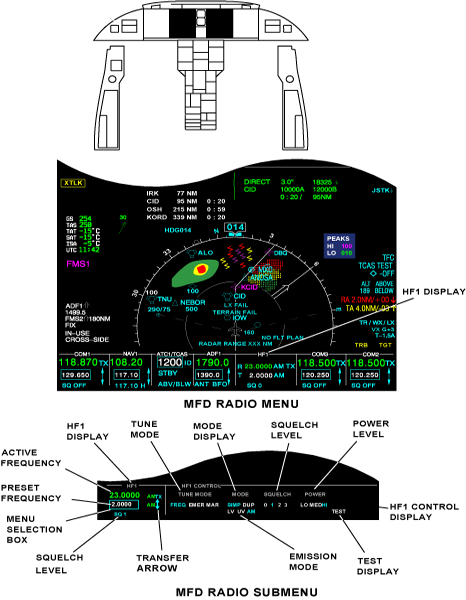
Two areas on the MFD show the radio system data. These are the MFD radio menu and the MFD radio sub-menu.
MFD Radio Menu
Each HF radio (and VHF communication (COM) and navigation (NAV) radio) has a primary radio display that is a box approximately 1 in (2.54 cm) square. All of these primary radio displays together are called the MFD radio menu.
The MFD radio menu shows in a row along the bottom of the MFD. The MFD radio menu includes HF Displays that shows the active and recall HF frequencies.
When the selection box is set in one of the MFD radio-menu columns, and the RADIO pushbutton on the DCP is pushed, an MFD radio sub-menu shows for the applicable radio.
MFD Radio Sub-menu.
The HF radio sub-menu is set with the DCP and is shown along the bottom of the MFD. For the display of the HF radio sub-menu, you must first use the MENU button to move the menu selection box to the HF frequency/channel. Then you must push the RADIO pushbutton.
The MFD radio sub-menu supplies more items for the applicable radio. Most control of the radios, other than to tune the frequency or channel, is done on the radio sub-menu Some controls replace the MFD radio menu with an MFD radio sub-menu.
An MFD radio sub-menu, for a radio, replaces the row of radio displays in the MFD radio menu. A radio shown in an MFD radio sub-menu is tuned as it is tuned in the MFD radio menu. An MFD radio sub-menu can fully control a radio.
The HF radio sub-menu (HF1 CONTROL, HF2 CONTROL sub-menu) shows the frequency/channel data and the other control items that follow:
- FREQ (frequency), EMER (emergency), and MAR (maritime), for the tune mode selection
- SIMP/DUP (simplex/duplex), for the transmission mode selection
- LV/UV/AM, for the emission mode selection
- SQ (squelch), for the squelch level selection
- POWER, for the transmit power level selection
- TEST, for the self-test activation.
Selection Box
Some of the DCP controls are used to show menus on the primary flight displays (PFDs) and/or MFDs, for different aircraft system functions. The selection box shows together with the applicable PFD and/or MFD menu to let the pilot/copilot do the selection of a specific menu item.
The DCP controls include the RADIO pushbutton which, when pushed, shows the MFD radio menu. The selection box is an important part of the MFD radio menu. The selection box is a movable box that shows in only one location on the PFD or MFD. Different controls move the selection box to different radio equipment in a radio menu display.
The selection box shows what radio equipment can be controlled or changed. When the MFD radio menu shows, the selection-box home-position can be in the bottom-left VHF or in the bottom-left HF COM radio-display. The communication radio that contains the home position is different for the pilot and copilot MFD. In the MFD radio menu or sub-menu, if no change is made for 20 seconds, the MFD radio menu shows. The selection box goes back to the radio menu home-position.
Active/Recall Frequencies
The active frequency shows in green at the top line, in the applicable radio column of the MFD radio menu and sub-menu.
Another important part of the MFD radio menu and sub-menu is the recall frequency. Each radio's recall frequency shows in smaller numbers below the active frequency of the radio. The recall frequency is a frequency that can be easily interchanged with the active frequency of the radio.
DCP Radio Controls
The DCP includes the radio tune controls that follow:
1/2 Pushbutton
If the MFD radio menu is shown, the 1/2 pushbutton on the DCP interchanges between the No. 1 and No. 2 systems of the shown radios.
If the NAV1, ADF1, and HF1 radios show, then the 1/2 pushbutton, when pushed, shows the NAV2, ADF2, and HF2 radios. If the NAV2, ADF2, and HF2 radios show, then the 1/2 pushbutton, when pushed, shows the NAV1, ADF1, and HF1 radios.
If the MFD radio menu is not shown, then when the 1/2 pushbutton on the DCP is pushed, the MFD radio menu comes into view. The selection box then shows in the default home position.
DME H Pushbutton
The DME H pushbutton on the DCP sets the DME hold function, of the DME system, on or off.
When the DME hold function is on, the DME radio stays tuned to the frequency it is tuned to. The VOR frequency is then tuned independently of the DME radio.
When the DME H pushbutton is pushed, the selection box shows around the NAV recall frequency of the NAV radio display.
If the NAV sub-menu shows before the DME hold is set, the sub-menu stays. If a menu, sub-menu, or list (other than the NAV sub-menu) shows on the same-side MFD or PFD, it goes out of view when DME H is pushed.
TUNE Control
The TUNE control, on the DCP, includes:
- A large outer button (coarse TUNE button)
- A small inner button (fine TUNE button)
- A pushbutton in the center (transfer pushbutton).
The coarse TUNE button is for the coarse tune control of the radio frequencies. The fine TUNE button is for the fine tune control of the radio frequencies. The transfer pushbutton is used to interchange the active frequency or channel and the recall frequency or channel. The coarse/fine TUNE buttons tune the applicable radio when the selection box is around a tune frequency or channel.
The coarse/fine TUNE buttons adjust the recall frequency on the VHF COM radios, the NAV radios, and the HF communication transceivers in simplex mode.
The coarse/fine TUNE buttons adjust the active frequency or channel on the air traffic control (ATC) transponder and the traffic surveillance system (TSS) and transponder unit, the DME transceivers, and the HF communication transceivers in duplex mode.
For the VHF COM, DME, and NAV radios, the coarse TUNE button tunes the three most-significant digits and the fine TUNE button tunes the three least-significant digits.
For the HF radio frequency and the ATC-transponder flight identification (FLT ID) number the coarse/fine TUNE buttons tune one digit at a time. One digit is set with the coarse TUNE button. The other digit is set with the fine TUNE button. A line shows under the selected digit.
If the selection box is in an MFD radio menu, but not around a radio frequency, the fine or coarse TUNE button moves the selection box. The fine or coarse TUNE button moves it to the nearest frequency or channel that can be tuned.
If the selection box is not in an MFD radio menu or sub-menu, then the fine or coarse TUNE button, when moved, causes the MFD radio menu to come into view. The selection box then shows in default home position. If the selection box is in an MFD radio sub-menu, and the sub-menu is not changed for 20 seconds, the radio menu shows, and the selection box goes back to its radio menu home-position.
If a menu or list is shown, other than on the MFD radio menu or sub-menu, the first notch of the fine or coarse TUNE button can erase it. The first notch of the fine or coarse TUNE button moves the selection box if the first notch erases a menu or list. The radio menu shows, and the selection box goes back to its radio menu home-position.
The fine and coarse TUNE buttons can also change the frequency that is in the tune window, in steps. The coarse TUNE button changes the necessary frequency in 1 MHz steps.
The fine TUNE button changes the frequency in 50 kHz steps or in 25 kHz steps. It does this for the first two steps, when the button is turned the other direction.
When the selection box is around a recall tune frequency or a channel, a two-direction arrow symbol shows to the right of the selection box. The arrow symbol shows that the transfer pushbutton on the DCP (center of the fine TUNE button), when pushed, will interchange two values. It will interchange the recall frequency or channel, and the active frequency in the selection box or channel in the selection box.
If the MFD radio menu or a sub-menu is shown, the transfer pushbutton can move the selection box. This only occurs when the selection box is not around a frequency or a channel. The transfer pushbutton moves the selection box to the tune frequency in the same primary radio display. If an MFD radio menu or sub-menu does not show, then the transfer pushbutton shows the MFD radio menu. It also moves the selection box to the home position.
RADIO Pushbutton
The RADIO pushbutton, on the DCP, when pushed, can have two different functions in relation to the radio-menu display condition.
If the MFD radio menu is not shown, the RADIO pushbutton, when pushed, shows the MFD radio menu. The selection box goes back to the home position.
If there is not another menu or list, other than the MFD radio menu shown, and the RADIO pushbutton is pushed, the radio display that contains the selection box, expands to show the radio sub-menu.
MENU/DATA Control
The MENU/DATA control, on the DCP, includes:
- A large outer button (MENU button)
- A small inner button (DATA button)
- A pushbutton in the center (PUSH SELECT pushbutton).
The MENU button is used to move the selection box through active menus.
The MENU button moves the selection box right and down, if turned clockwise. The MENU button moves the selection box left and up, if turned counterclockwise. The MENU button has no end stops.
The selection box moves to the left side of the MFD on the clockwise notch, after it shows in its farthest right position. The selection box moves to the right side of the MFD on the counterclockwise notch, after it shows in its farthest left position.
The MENU button moves the selection box to the necessary radio tune frequency or channel. Other than to tune the frequency or the channel, radio control is done on a radio sub-menu. If the selection box is not in the MFD radio menu, the MENU button moves the selection box to the necessary item.
The DATA button is used to increase a numeric value or to move the selection box.
If the selection box is around a numeric value, the DATA button increases that value, if it is turned clockwise. It decreases that value, if it is turned counterclockwise.
If the selection box is around an item that is not numeric, each clockwise DATA-button notch moves the selection box through the possible positions (right and down). Each counterclockwise notch goes though the possible selections to the left and up.
The PUSH SELECT pushbutton is used to set a value or change an item selection.
If the selection box is around a numeric value, and the numeric value is changed, then the PUSH SELECT pushbutton sets that value. The value is also set if the changed value is not adjusted for 3 seconds, or if the selection box moves. The selection box goes back to its home position in the MFD radio menu after 20 seconds with no adjustments. If the selection box is around an item that is not numeric, the PUSH SELECT pushbutton changes the item through its possible selections.
RSP Radio Controls
The RSP can change the operation of the MFD and the PFD with the controls that follow:
- TUNE reversion switch
- LEFT DISPLAYS reversion-switch
- RIGHT DISPLAYS reversion-switch.
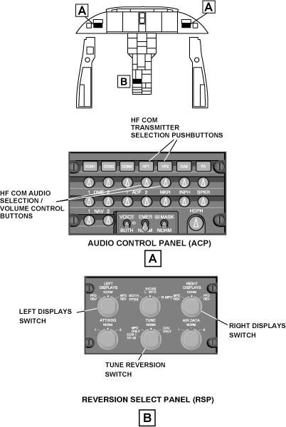
TUNE Reversion Switch
The TUNE reversion switch, on the RSP, lets the pilots do the selection of different radio tuning modes. In usual conditions, radio tuning is done in the normal (NORM) tune mode (TUNE reversion switch, on the RSP, set to NORM position).
When the TUNE reversion switch, on the RSP, is in the CDU ONLY position, the radio menu and radio sub-menus go out of view. Also, the RADIO, 1/2, or DME H pushbuttons on the DCP, when pushed, show SELECTION INACTIVE on the same-side PFD, for 5 seconds. In the CDU ONLY mode, the MFDs cannot tune the HF transceivers, and the CDUs tune the HF transceivers directly. The CDU tunes the same-side radios only when the RSP TUNE reversion-switch is in the CDU ONLY position.
When the TUNE reversion switch, on the RSP, is in the MFD ONLY position, the CDUs do not tune the HF transceiver. The MFDs ignore signals from the CDU, if it tries to tune the HF transceivers. In this MFD ONLY mode, the MFD tunes the HF transceivers as in the normal operation mode.
If the TUNE reversion switch, on the RSP, is in the COM1 121.50 position, then the MFD operates as usual, but the COM1 radio does not. The COM1 radio is automatically tuned to the emergency frequency 121.50 MHz.
LEFT DISPLAYS Reversion-Switch
The LEFT DISPLAYS reversion-switch, on the RSP, controls which pilot display shows what data. When the pilot PFD and MFD are serviceable, the switch is in the NORM position.
When the pilot PFD or right MFD has a fail condition, the LEFT DISPLAYS reversion-switch is set to the applicable PFD REV or MFD REV position.
When the LEFT DISPLAYS reversion-switch is in the PFD REV position, the pilot PFD shows a compressed PFD display. When the LEFT DISPLAYS reversion-switch is in the MFD REV position, the pilot MFD shows a compressed PFD display.
The compressed PFD display does not show the MFD radio menu and the MFD radio sub-menu. Also, the selection box goes out of view when the MFD radio menu and MFD radio sub-menu go out of view and no other menu shows.
RIGHT DISPLAYS Reversion-Switch
The RIGHT DISPLAYS reversion-switch, on the RSP, controls which copilot display shows what data. When the copilot PFD and MFD are serviceable, the switch is in the NORM position. When the copilot PFD or right MFD has a fail condition, the RIGHT DISPLAYS reversion-switch is set to the applicable PFD REV or MFD REV position.
When the RIGHT DISPLAYS reversion-switch is in the PFD REV position, the copilot PFD shows a compressed PFD display. When the RIGHT DISPLAYS reversion-switch is in the MFD REV position, the copilot MFD shows a compressed PFD display.
The compressed PFD display does not show the MFD radio menu and the MFD radio sub-menu. Also, the selection box goes out of view when the MFD radio menu and MFD radio sub-menu go out of view and no other menu shows.
HF-Radio Basic Operations
The basic operations of the HF communication system are usually controlled with the MFD radio menu and the DCP controls.
If the MFD shows another menu or list, the pilot/copilot must first push the RADIO pushbutton, on the DCP, until the radio menu shows on the MFD. The MFD radio menu shows the primary display and control functions for the different radio equipment. The pilot or the copilot can control the same-side or the opposite-side HF radios with the MFD radio menu and the DCP controls.
Radio Tuning
The HF radios can be tuned with the MFD radio menu or the MFD radio sub-menu. To tune an HF radio with the MFD radio menu, the MENU button, on the DCP, must be turned to move the selection box to the applicable frequency or channel that must be tuned. Then the frequency in the selection box is adjusted to the correct value with the fine TUNE button and the coarse TUNE buttons on the DCP. The fine TUNE button and the coarse TUNE button are turned clockwise to increase the value and counterclockwise to decrease the value. When the correct value is obtained, the PUSH SELECT pushbutton, on the DCP, is pushed to set the new frequency value.
To tune an HF radio with the MFD radio sub-menu, the applicable HF CONTROL sub-menu is first shown. To show this sub-menu, the selection box, on the MFD menu, must be located on the applicable item (HF1 or HF2) and the RADIO pushbutton, on the DCP, must be pushed. The MENU button, on the DCP, is then used to move the selection box around the frequency or channel that must be tuned. Then, the frequency is tuned with the same procedure used to tune the frequency with the MFD radio menu.
Note:
To tune to a PRESET HF frequency (or to change a preset HF frequency), the flight crew uses a PRESETS line-select key (LSK) on the CDU (a description of the CDU pages for the HF radios follows).
To replace the active frequency with the frequency value of the recall frequency, the selection box is first moved around the recall frequency adjacent to the transfer symbol.
Then, the transfer pushbutton, on the DCP, is pushed to interchange the recall frequency and the active frequency.
Tune Mode Selection
The MENU button on the DCP moves the menu selection box to the tune mode control (FREQ, EMER, or MAR) on the HF sub-menu. The DATA button, or the PUSH SELECT button, sets the tune mode. The annunciation, for the mode that is on, becomes larger and shows in cyan.
Transmission Mode Selection
Control of the transmission mode (SIMP/DUP) is only possible when the frequency (FREQ) mode is set. The MENU button, on the DCP, moves the menu selection box to the operational mode control (SIMP, DUP), on the HF sub-menu. The DATA button, or the PUSH SELECT button, sets the simplex or duplex mode. The annunciation, for the mode that is on, becomes larger and shows in cyan. Maritime (MAR) mode is always set to duplex (DUP) mode.
Emission Mode Selection
Emission mode (LV, UV, AM) control is only necessary when the frequency (FREQ) mode is set. The MENU button, on the DCP, moves the menu selection box to the emission mode control (LV, UV, AM) on the HF sub-menu. Available selections are lower sideband voice (LV), upper sideband voice (UV), and amplitude modulation (AM).
Squelch Level Control
The MENU button, on the DCP, moves the menu selection box to the squelch level control (0, 1, 2, or 3) on the HF sub-menu. The DATA button, or the PUSH SELECT button, sets the squelch level. Possible squelch levels are off (SQ0), minimum (SQ1), SQ2, or maximum (SQ3). The annunciation, for the squelch level that is set, becomes larger and shows in cyan.
Power Level Control
The MENU button, on the DCP, moves the menu selection box to the power level control (LO, MED, or HI) on the HF sub-menu.
The DATA button or the PUSH SELECT button sets the power level. The three available power levels are high (HI), medium (MED), and low (LO).
The annunciation, for the power level that is set, becomes larger and shows in cyan.
Test Activation
Self-test operation for the HF communication system can be initiated from the HF CONTROL radio sub-menu. The MENU button, on the DCP, is turned to move the selection box to the TEST display. Then the DATA button or the PUSH SELECT pushbutton, on the DCP, is used to put the applicable HF radio into a TEST mode operation. TEST operation results are shown to the flight crew on the MFD and/or the CDU.
Transmit Operation
Selection of an HF transceiver as the active transmitter is done when the applicable selection pushbutton (HF1 or HF2), on the ACP, is pushed. The HF transceiver is set to the transmit mode with the radio transmit (R/T) switch on the pilot/copilot control wheel (when a boom microphone is used) or with the microphone push-to-talk (PTT) switch (when the pilot/copilot hand microphone is used).
When an HF transceiver is in the transmit mode, a TX transmit symbol shows adjacent to the active frequency on the MFDs.
For more details on ACP transmitter-selection controls refer to the audio integrating system.
Receive Operation
Selection of an HF transceiver as the audio source is active when the applicable ACP audio selection/volume-control button (HF1 or HF2), on the ACP, is in the pulled-out position. The same ACP control button also lets the pilot/copilot adjust the volume of the audio output from the HF transceivers.


CDU Controls and Displays
The control/display functions for the HF communication system show on the CDU pages that follow:
TUNE Page 2/2
The TUN (tune) key on the CDU, when pushed, shows the radio TUNE page 1/2. The NEXT key on the CDU, when pushed, gives an access to TUNE page 2/2. The radio TUNE pages are used to tune the communication and navigation radios and to control their operation modes. They also give access to CDU pages that give more radio control/display functions.
Correct entries on this CDU page, to tune the HF radios include:
- The simplex frequency
- The duplex frequency
- Maritime channel
- Emergency channel
- Preset number.
To tune an HF radio, the flight crew records the frequency or the preset number on the scratch-pad line. Then the flight crew pushes the applicable HF1 line-select key or HF2 line-select key to move the frequency to a data field. If the frequency is correct, it shows in the data field and the radio immediately tunes again. The flight crew pushes the HF1 line-select key or the HF2 line-select key again to see the HF1 CONTROL page or the HF2 CONTROL page.
The HF1 (2) SQUELCH display shows the level at which squelch is set for the HF radios. The flight crew pushes the line-select key adjacent to the arrow that points up, to increase the squelch level. The flight crew pushes the line-select key adjacent to the arrow that points down, to decrease the squelch level. The possible squelch selections are SQ0, SQ1, SQ2, and SQ3.
The TUNE page 2/2 supplies displays for the control of the HF emission mode (LV, UV or AM). Emission mode control is only necessary when the FREQ mode is set.
The selective calling (SELCAL) function is selected ON/OFF on the TUNE 2/2 page. There is a line-select key that shows SELCAL. When the LSK is pushed, the ON/OFF selection is made.
HF 1 (2) CONTROL Page
The flight crew pushes the HF1 (2) line-select key on the TUNE page, to show the applicable HF 1 CONTROL page or HF 2 CONTROL page. The HF1 (2) line-select key on the HF, when pushed, records the data on the scratch-pad line as the HF 1 active frequency. Correct entries on this CDU page, to tune the HF radios include:
- The simplex frequency
- The duplex frequency
- Maritime channel
- Emergency channel
- Preset number.
The squelch level shows SQ0, SQ1, SQ2, or SQ3. There is a line-select key that has an arrow that points up and a line-select key that has an arrow that points down. The flight crew pushes one of these line-select keys to adjust the squelch level.
The HF 1 (2) CONTROL page supplies displays for the control of the HF emission mode (LV, UV, or AM). Emission mode control is only necessary when the FREQ mode is set.
The flight crew pushes the POWER line-select key to change the output power selection. The possible power levels are LO (low), MED (medium), or HI (high). The power level annunciation becomes larger to show the selection that is in operation.
The flight crew pushes the TEST line-select key to do a test of the HF communication system. The TEST annunciation becomes larger while this mode is in operation. The HF test time period is approximately 4 sec.
The MODE line-select key, when pushed, changes the selection of the mode that is in operation. The possible mode selections are FREQ (frequency), EMER (emergency), or MAR (maritime). The MODE annunciation becomes larger to show which selection is in operation.
The PRESETS line-select key, if pushed, shows an HF1 PRESETS page. On this page, the flight crew must push an HF1 line-select key, to record the data on the scratch-pad line as the active HF1 frequency. If the scratch-pad line contains no data, the flight crew can push a preset line to move a set frequency to the active frequency field.
SELECTIVE CALLING Page
The SELECTIVE CALLING page shows the SELCAL code, SELCAL configuration messages, and automatic detection functionality. The SELCAL code is shown in green when the active code and frequency are correct. When the SELCAL code is shown in yellow when the RIU does not accept the SELCAL code. The SELCAL code is shown in white if the detection function is set to OFF.


11/25/15
System Interface
The HF communication system has interfaces with the aircraft systems/components that follow:
- Audio Integrating System
- Electronic Flight-Instrument System (EFIS)
- Flight Management System (FMS)
- Vertical Stabilizer
Signals between the components of the HF communication system are transmitted as follows:
- HF transceiver No. 1 sends and receives RF signals to/from the HF antenna through the HF1 antenna coupler
- HF transceiver No. 2 sends and receives RF signals to/from the HF antenna through the HF2 antenna coupler
- HF transceiver No. 1 sends and receives data to/from the HF1 antenna coupler on fiber-optics bus
- HF transceiver No. 2 sends and receives data to/from the HF2 antenna coupler on fiber-optics bus.
The control, monitor, and display functions for the HF communication system operate through interfaces with the components that follow:
- RIUs
- CPEs
- CDUs
- RSP.
RIUs
The RIUs send and receive analog audio to and from the HF transceivers as follows:
- HF transceiver No. 1 supplies an analog audio output to the RIU No. 1
- HF transceiver No. 2 supplies an analog audio output to the RIU No. 2
- HF transceiver No. 1 gets an analog audio input from the RIU No. 1
- HF transceiver No. 2 gets an analog audio input from the RIU No. 2.
The RIUs receive tune data from the HF transceivers as follows:
- Tune data processed by the HF transceiver No. 1 is supplied to RIU No. 1 on L-HF-1 ARINC 429 data bus
- Tune data processed by the HF transceiver No. 2 is supplied to RIU No. 2 on R-HF-1 ARINC 429 data bus.
Each RIU receives tune-in-progress data (HF TUNE IN) from the applicable HF transceivers (HF TUNE OUT).
The RIUs send the HF radio data to the MFDs as follows:
- RIU No. 1 supplies data on LA-RIU-6 and LB-RIU-6 ARINC 429 data bus to MFD No. 1
- RIU No. 2 supplies data on RA-RIU-6 and RB-RIU-6 ARINC 429 data bus to MFD No. 2.
The key-line input from each RIU to the applicable HF transceiver tells the transceiver to transmit when the push-to-talk (PTT) switch of the active microphone is pushed.
Traffic Surveillance System
The HF transceiver and the traffic surveillance system (TSS) unit receive input signals from the RIU No. 1 on LA-RIU-8 and LB-RIU-8 ARINC 429 low speed data busses.
CPEs
The RIUs supply digital audio output to the CPEs as follows:
- RIU No. 1 supplies a digital audio output to the CPE No. 1 through LA-RIU-3 and LB-RIU-3 ARINC 429 data busses
- RIU No. 2 supplies a digital audio output to the CPE No. 2 through RA-RIU-3 and RB-RIU-3 ARINC 429 data busses.
When the observer third audio system option is installed, the RIUs supply digital audio output to the third CPE as follows:
- RIU No. 1 supplies a digital audio output to the CPE No. 3 through LA-RIU-5 and LB-RIU-5 ARINC 429 data busses
- RIU No. 2 supplies a digital audio output to the CPE No. 3 through RA-RIU-5 and RB-RIU-5 ARINC 429 data busses.
The audio output is then supplied to the pilot and copilot side-console headset jacks and to the observer headset jacks.
Also, the audio from the pilot, copilot and observer microphones are sent to the CPEs. From the CPEs, the audio, in digital format, is transmitted to the RIUs.
CDUs
The HF transceivers receive data from the CDUs as follows:
- The HF transceiver No. 1 receives tune data from CDU No. 1 on L-CDU-6 ARINC 429 data bus
- The HF transceiver No. 2 receives tune data from CDU No. 1 on L-CDU-7 ARINC 429 data bus.
The HF transceiver No. 2 receives the data from CDU No. 2, on R-CDU-6 ARINC 429 data bus. Also, when two CDUs are installed, they give to each other control data to set which CDU has the control.
RSP
The HF transceivers receive discrete inputs from the RSP for the functions that follow:
- Selection of CDU ONLY tune mode (CDU TUNE input)
- Selection of display reversion mode (MFD1/PFD1 REV and MFD2/PFD2 REV inputs)
The RSP also sends these discrete outputs to CDU No. 1 and CDU No. 2.


System Test
The HF communication system includes a self-test function. The test function operation can be started from the MFD radio menu or from a CDU control page. Access to the self-test results is possible through the maintenance diagnostic computer (MDC). During the test period (approximately 40 seconds), the active HF frequency cannot be tuned and there is no access to the related active modes.
MFD TEST Selection
The MENU button on the DCP moves the menu selection box to the TEST indication on the HF sub-menu. The PUSH SELECT button on the DCP sets the HF self-test.
When the test function is on, the dimension of the TEST indication increases and becomes cyan. If the echo from the radio is not available or does not agree with the frequency selection, the applicable frequency indication changes from green to yellow.
CDU TEST Selection
On the CDU, test selection is made on the applicable HF CONTROL page, with the TEST line-select key. When the test function is not on, TEST indication shows in white.
When the test function is on, the dimension of the TEST indication increases and becomes cyan. If the test is not satisfactory, HF tuning error-messages show in white in the scratch-pad area.
10/14/20
Component Location Index
| Component Location Index | |||
|---|---|---|---|
| IDENT | DESCRIPTION | LOCATION | IPC REF |
| A61 | HF TRANSCEIVER NO. 1 | FS801.12, WL91.41,RBL15.00,ZONE(S) 312 | 23-12-01 |
| A62 | HF TRANSCEIVER NO. 2 | FS764.22, WL76.78,RBL3.00,ZONE(S) 312 | 23-12-01 |
| - | HF TRANSCEIVER MOUNTING TRAY NO. 1 | FS801.12, WL91.41,RBL15.00,ZONE(S) 312 | 23-12-05 |
| - | HF TRANSCEIVER MOUNTING TRAY NO. 2 | FS764.22, WL76.78,RBL3.00, ZONE(S) 312 | 23-12-05 |
| CP5 | HF ANTENNA COUPLER NO. 1 | PANEL(S) 340BB, FS784. 61,WL162.40,BL0.00, ZONE(S) 340 | 23-12-09 |
| CP6 | HF ANTENNA COUPLER NO. 2 | PANEL(S) 340BB, FS784. 61,WL162.40,BL0.00, ZONE(S) 340 | 23-12-09 |
| - | HF ANTENNA-COUPLER MOUNTING TRAY | PANEL(S) 340BB, FS784. 61,WL162.40,BL0.00, ZONE(S) 340 | 23-12-13 |
| - | HF ANTENNA FEEDLINE | PANEL(S) 340BB, FS784. 61,WL162.40,BL0.00, ZONE(S) 340 | 23-12-17 |