


05/30/23
Overview
 Note:
Note:
The SATCOM System is available via optional SB 350-23-012.
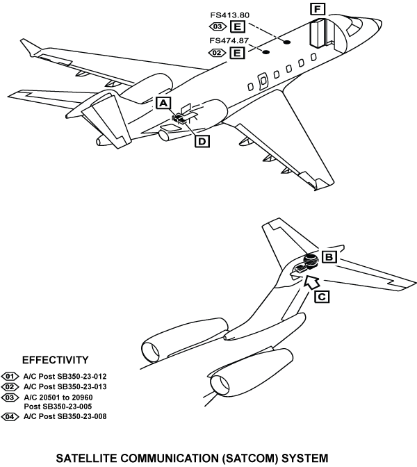
The satellite communication (SATCOM) system makes voice and data communications possible at almost all locations in the world. SATCOM is also better than other long-range communication systems in connectivity, voice quality, reliability, and traffic volume capacity. The SATCOM system has three primary systems that follow:
- Space system
- Ground system (ground earth stations (GES))
- Aircraft earth station (AES).
The space system is a system of satellites. The satellites are the two-way relay between the AES and the GES. The satellites are in geosynchronous orbits 36,000 km (22,300 mi) above the equator. The satellites operate above an area that is between 75 degrees north and south latitude and that is around the world. There is an overlap of areas above which each satellite operates.
The ground system has GESs and local/long distance telephone networks. The GESs interchange data between the space system and the public or private telephone and data networks. The GESs transmit to and receive from the satellites with C-band communications, and are connected with public telephone and data networks for worldwide communications.
Each GES is privately owned. The local national public telephone and telegraph (PTT) organizations operate the GES. The long distance and local telephone companies are connected and make the public switched telephone network (PSTN). The PSTN interchanges data between the GES network and the person that uses the system.
The AES operates with the satellite communications system of the international maritime satellite organization (INMARSAT). The AES uses the satellite to give digital communication between the aircraft and the GES. The AES can get an access to the INMARSAT satellites with L-band communications. The satellites then transmit and receive the data with C-band to the GES.
The GES can transmit packet data (such as ARINC communications addressing and reporting system (ACARS)/airborne flight information system (AFIS), that gives data about aircraft conditions, departure time, arrival time, or flight delay time). The GES can also transmit telephone communications (such as voice, fax, and PC modem data).
The SAT-2200 International Marine/Maritime Satellites (INMARSAT) SATCOM system is a reliable, transoceanic long-range voice and data communication system with a wide range of services such as AIRCOM Communications Addressing and Reporting System (ACARS), and cabin services.
- For data communication, the SATCOM data llnk channel supports classic ACARS data link or FANS/ATN (option). In addition, the system is capable of interfacing with a cabin system router for 64Kbps Swift 64 or max 432 Kbps Swift Broadband (SBB) internet access.
- For voice communication, the SATCOM system interfaces with the cabin phone system PABX for classic aero and low-cost SBB calls.
SATCOM provides an alternate means for existing avionics functions such as line-of-sight (LOS) ACARS. The ACARS link utilizes a VHF communication channel, however the LOS requirement is eliminated when the VHF is out of range. The ACARS data link utilizes SATCOM to include air traffic control (ATC) functions such as in-flight clearance acknowledgment reporting and position information through the automatic dependent surveillance-contract (ADS-C) system.
The SATCOM system is capable of providing aeronautical mobile satellite services (AMSS) by facilitating voice and data services over the L-band INMARSAT satellite networks I-3 and I-4. INMARSAT provides global coverage, except at the Earth poles, as an alternative to VHF communications. SATCOM services provided are:
- Classic Aero H+: the classic service utilizes the I-3 or I-4 network to provide data-2 packet data services at 600, 1200, or 10500 bps over the PRT channel combination and half-rate circuit switched voice over the C channel. Safety services is a key feature enabling ACARS and future air navigation system (FANS).
- Swift64 (S64): the services utilizes the I-3 network for circuit switched (M4) or packet switched mobile packet data services (MPDS) at 64 Kbps.
- Swift Broadband (SBB): the service utilizes the I-4 network to provide broadband circuit and packet switched services typically with the data rates of up to 432 Kbps. per channel as well as the SBB associated voice channel(s). The equipment can be configured for either single or dual SBB.
Note: Refer to the Aircraft Maintenance Manual (Part 2) for maintenance procedures.
INMARSAT is an international organization that operates and maintains multiple geostationary satellites and satellite networks (I-3 and I-4). For more information about I-3 and I-4 satellite beam coverage, refer to the INMARSAT website - www.inmarsat.com
I-3 satellites provide INMARSAT services for aviation, shipping, and land-mobile users. The satellites connect to ground telecommunications system though a network of GESs. Each I-3 satellite is located over an ocean region (OR) the current OR are:
- Atlantic ocean region - East (AOR-E)
- Atlantic ocean region - West (AOR-W)
- Indian ocean region (IOR)
- Pacific ocean region (POR).
I-4 satellites provide worldwide Swift Broadband (SBB) service. Each I-4 satellite has 19 wide spot beams, 228 narrow spot beams, and is capable of accommodating many separate, simultaneous SBB sessions. The SBB service and I-4 satellites support broadband applications. The current I-4 satellites are:
- AMERICAS
- EMEA (Europe, Middle East, and Africa)
- APAC (Asia-Pacific).
On A/C Post SB 350-23-013
The satellite communication (SATCOM) system makes voice and data communications possible at almost all locations in the world. SATCOM is also better than other long-range communication systems in connectivity, voice quality, reliability, and traffic volume capacity.
The Iridium Communication System (ICS-220) gives the unique capabilities of a dual channel voice system combined with a dedicated iridium transceiver. This unique combination allows the ICS-220 to support Aircraft Communications Addressing and Reporting System (ACARS) communication links as the same time along the Iridium network as an approved secondary means of uninterrupted communication.
The SATCOM system has three primary systems that follow:
- Space system
- Ground system (ground earth stations (GES))
- Aircraft earth station (AES)
The space system is a system of satellites. The satellites are the two-way relay between the AES and the GES. The satellites are in geosynchronous orbits 781 km (485 mi) above the equator with an inclination of 86.4 degrees. There is an overlap of areas above which each satellite operates.
The ground system has GESs and local/long distance telephone networks. The GESs interchange data between the space system and the public or private telephone and data networks.
Each GES is privately owned. The local national public telephone and telegraph (PTT) organizations operate the GES. The long distance and local telephone companies are connected and make the public switched telephone network (PSTN). The PSTN interchanges data between the GES network and the person that uses the system.
The AES operates with the satellite communications system of the Iridium network. The AES uses the satellite to give digital communication between the aircraft and the GES. The AES can get an access to the Iridium network satellites with L-band communications. The satellites then transmit and receive the data to and from the GES.
The GES can transmit packet data (such as ARINC communications addressing and reporting system (ACARS)/airborne flight information system (AFIS), that gives data about aircraft conditions, departure time, arrival time, or flight delay time). The GES can also transmit telephone communications (such as voice, fax, and PC modem data).
The satellite communication (SATCOM) system is a compatible ARINC 781 that consists of the main components that follow:
- Satellite data unit (SDU)
- SDU mounting tray
- SATCOM Iridium Transceiver
- SATCOM Iridium Transceiver Mounting Tray
- SATCOM Iridium Configurational Identity Module
- SATCOM Iridium Antenna
- SATCOM Aircell Air to Ground Antenna (Post SB 350-23-008)
The ICS-220A iridium SATCOM system is a reliable, transoceanic long-range voice and data communication system with a wide range of services such as AIRCOM Communications Addressing and Reporting System (ACARS), and cabin services.
- For data communication, the SATCOM data link channel supports classic ACARS data link or FANS/ATN (option).
- For voice communication, the SATCOM system interfaces with the cabin phone system PABX for classic aero.
SATCOM provides an alternate means for existing avionics functions such as line-of-sight (LOS) ACARS. The ACARS link utilizes a VHF communication channel, however the LOS requirement is eliminated when the VHF is out of range. The ACARS data link utilizes SATCOM to include air traffic control (ATC) functions such as in-flight clearance acknowledgement reporting and position information through the automatic dependent surveillance-contract (ADS-C) system.
The Iridium Network provided communications globally, including the polar area, without the interruption of coverage. Additionally there are sufficient ARINC 429 interfaces that support until three ARINC 739A compliant MCDU devices. The MCDU devices can dial and respond to let users to make and receive calls on the Iridium networks. In all there are three ARINC 429 compliant transmitter circuits and six receiver circuits. The 2-MCU package supplies all these features for a minimal footprint in the aircraft equipment bay to support the dual Satcom installations.


SATCOM Satellite Data Unit
The SATCOM satellite data unit (SDU-2200) is a line replaceable unit. The SDU-2200 combines the receiver, radio frequency source and high power amplifier. The SDU provides ARINC 429 digital interfaces for aircraft avionics. The SDU provides the central data processing for communication with the satellites. The SDU encompasses modulation, forward error correcting (FEC) coding, data formatting, signal processing and interface functions. The SDU provides the RF power for transmission for the satellite and receives at L-band through a connection to the diplexers/low noise amplifier (DLNA).
The SDU incorporates two internal channel cards, channel card 1 (CC1) and channel card 2 (CC2). CC1 provides Swift Broadband (SBB) or Swift64 services while the CC2 provides simultaneous Classic data and voice and SBB services. Both cards provide SBB packet-switched background or streaming data as well as circuit switched voice. SBB circuit switched voices is provided with an AMBE+2 voice codec.
The SDU outputs the SDU-4 429 bus to the IOC No. 2, providing the IOC with the SATCOM fault summary words and equipment ID.
The SDU sends ARINC 664 bus signals to and receives ARINC 664 bus signals from the forward maintenance panel.
The DATALOAD ENABLE IN discrete, from the software data switch, allows the data loading function to load ORT files into the SDU. Data loading can only be performed while the aircraft is on the ground. The SDU is provided a weight-on-wheels discrete from the CVR relay, indicating the aircraft is on the ground and the data-loading can be performed.
Owner Requirements Table (ORT)
The secure ORT contains the files which are critical for operation of aircraft communications. This includes airframe configuration items, modes of operation, satellite parameters, ethernet interface configuration, cockpit voice configuration, high rate in the global beam, antenna configuration, SDU to antenna cable loss global navigation satellite system (GNSS) frequency algorithm, WOW configuration, barred cabin numbers, and passive intermod testing parameters. In addition, the user ORT contains non-critical files that can be customized for the end user. If no custom user ORT file is provided, the SDU reverts to a default file. It contains logon parameters, ethernet port configuration, including IP compression, cockpit voice service configuration, and telephone directory.
The ORT file is checked by the SDU every time the SDU boots over the SDU DATA OUT RS422 bus. When the SDU receives a signal back from the SCM over the SCM DATA IN RS422 bus, the SDU compares the ORT file in its memory to that in the SCM. If the ORT files do not match, the SDU loads the file from the SCM into its memory.
If specified in the ORT, the initial system logon happens immediately after the SATCOM system powers-up with no CDU input required. If the ORT is not configured as such, you must initiate the logon from the CDU.
Maintenance Port
The SDU is equipped with a maintenance port located on its front panel. The maintenance port provides the physical connection to a password protected maintenance port utility that provides a system interface for users or service personnel who need to monitor or troubleshoot the system.
Self-Test Button
The front panel of the SDU has a recessed button labeled Test. The self-test pushbutton is a recessed button located behind a red protective cap. To push the test button, use a small and thin tool with no sharp edges. The self-test button is activated with momentary push. The full power-on reset is done when a push and hold for greater than five seconds. When the SDU self-test is done, the front panel LEDs alternate flashes.
Front Panel Light Emitting Diode (LED) Display
When the SDU self test is done, the front panel LEDs alternate flashes. The front panel of the SDU has two LEDs to indicate unit status:
- one green LED labeled Power - LED is steady on with power applied
- one red LED labeled Fault - LED is steady on when a fault exists.
Note:
The LEDs indicate the results of the self-test.

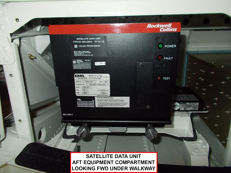
SATCOM Satellite Data Unit Mounting Tray
The SDU mounting tray supports the SDU-2200. Cooling air to the SDU-2200 is provided by a fan on the mounting tray. The SATCOM SDU mounting tray is installed in the aft avionics compartment (FS765). The SDU attaches to the SATCOM SDU mounting tray. Two hold-down clamps on the tray engage the hold-down hooks on the SDU and attach the SDU to the mounting tray.

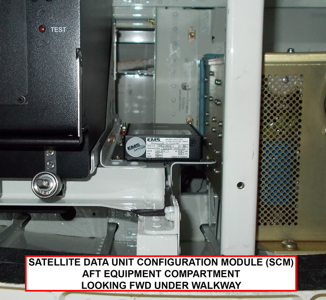
SDU Configuration Module
The SDU configuration module (SCM) is the companion unit that stores the configuration of the SDU. This configuration data is also stored in the SDU non-volatile memory. Two types of configuration data files can be stored: the secure owner requirements table (ORT) and the user ORT. The SCM also stores the Swift64 forward and reverse IDs, and the SBB universal subscriber module (USIM). The SDU provides the SCM operational power over the +12 VDC out power output.
The SCM can accommodate up to four universal subscriber identity modules (USIM) that store subscriber information for the SBB network.
By storing configuration information independent of the SDU, the SCM facilitates efficient SDU replacement (if necessary). A new SDU that replaces a faulty SDU does not require any configuration. All configuration information is obtained from the SCM.

SATCOM High Gain Antenna
The SATCOM antenna is an L-band high gain antenna. The SATCOM antenna transmits and receives to the INMARSAT satellite. The antenna is mounted on the tail of the aircraft such that its operation does not interfere with an other communication system or any other system operating in the RF spectrum. The electrically steered antenna is a phased array that provides the processing to create the transmit and receive beams. These beams are steered by the beam steering unit (BSU) which receives pointing information from the SDU over the ANTENNA MULTI CONTROL 429 HS TX bus. The L-band antenna outputs the ANTENNA BITE 429 TX bus to the SDU, providing the BSU response, maintenance, and configuration words.

SATCOM Diplexer/Low-Noise Amplifier (DLNA)
The SATCOM diplexer/low-noise amplifier (DLNA) is a type-F diplexers/low noise amplifier (DLNA). The DLNA is designed to allow for the simultaneous reception and transmission of the satellite signals over the same antenna RF interface, ANT RF. The DLNA has a transmit port and receive port RF OUT, on the SDU side. The SATCOM DLNA amplifies the very weak signals from the satellite.
The DLNA combines the receive and transmit RF signals into a single path for interface from and to the antenna. On the transmit path, the DLNA filters the signal from the satellite communications avionics high power amplifier (HPA (internal to the SDU)) before combining it with the receive path signal. On the receive path, the DLNA filters the receive signal from the antenna before amplifying it with the DLNA. The signal is then received by the SDU for demodulation.

12/21/15
SATCOM Iridium Transceiver (On A/C Post SB 350-23-013)
The ICS-220A Iridium Transceiver Module is a 2 MCU 3-transceiver device. It put together dual channels of global voice and 2400 BPS data service with a third “ Short Burst Data“ SBD channel.
The ICS-220A SDU lets the connections to the flight compartment audio system, the MCDUs and CMU through standard ARINC 429 connection. It can also establish the telecom connections via the standard telephony device through standard 2 Wire “ Tip and Ring” circuits or 4 wire audio connections. Telecom feature includes intercom call, call transfer, conference and follow on dial. The ICS-220A has a connection for an external configuration storage device. The SDU operates in the frequency range from 1,616.0 to 1,626.5 MHz.
12/21/15
SATCOM Iridium Transceiver Mounting Tray (On A/C Post SB 350-23-013)
The MCU mounting tray holds the SDU with the aircraft structure. The tray also let the SDU to interface with other system components as it holds the SDU connector.
12/21/15
SATCOM Iridium Configurational Identity Module (On A/C Post SB 350-23-013)
The CIM operates as the remote SIM reader that let the ICS-220 to operate with the SIM cards stored externally in this module. It also keeps ICS-220 configuration, and the ATS and AOC directory files. Configuration storage is a same function for the two systems.
05/30/23
SATCOM Iridium Antenna
The SATCOM Iridium antenna is a low profile antenna with circular shape. It operates in the frequency band of 1,616.0 MHz to 1,626.5 MHz. The SATCOM Iridium antenna is installed on the top fuselage, at FS413.80 on A/C 20501 to 20960 Post SB 350-23-005 and at FS474.87 on A/C Post SB 350-23-013.
12/31/21
SATCOM Aircell Air to Ground Antenna (On A/C Post SB 350-23-008)
The SATCOM aircell air-to-ground (ATG) broadband antennas are mounted to the bottom of the belly fairing of the aircraft. The forward antenna is installed at FS 595.00 and the aft antenna is installed at FS 700.00 of the fuselage.
System Operation
SATCOM System Interfaces
The SATCOM satellite data unit (SDU) has interfaces with the components that follow:
- SDU configuration module
- SATCOM diplexer/low-noise amplifier (DLNA)
- SATCOM high gain antenna (HGA)
- Control display unit (CDU) No. 1
- Control display unit (CDU) No. 2
- Radio interface unit (RIU) No. 1
The SATCOM SDU get radio frequency signal from the DLNA. The SATCOM SDU gives radio frequency signal to the DLNA.

Control and Displays
SATCOM System Controls
The pilot/copilot uses the control display unit (CDU) to control the SATCOM system operation.
The CDU has 12 line select keys (LSK) along the sides of the display. Six of the LSKs are along the right side of the display and six LSKs are along the left side of the display. The LSKs along the left side of the display are 1L to 6L from the top to the bottom. The LSKs along the right side of the display are 1R to 6R from the top to the bottom.
The pilot/copilot uses the CDU LSKs to select the applicable menus to display and/or set the different SATCOM system data.
SATCOM System Displays
The SATCOM system menus SATCOM MAIN MENU and SATCOM MAINT MENU on the CDU, the data that follows can be displayed/controlled:
- Built-in test equipment (BITE) status
- System bus data
- System configuration data
- SATCOM reset functions
- SATCOM options
- SATCOM audio configuration
- SATCOM installation parameters
- Owner's requirements table (ORT) data
SATCOM BITE STATUS Pages
The SATCOM BITE STATUS pages show built-in test results from each line replaceable unit (LRU) and subassembly of the SATCOM system. Messages about these results are as follows:
- OK - the LRU is prepared for normal operation
- FAULT - the LRU has an abnormal condition
- NO DATA - the LRU has an sign status matrix (SSM) of no computed data (NCD)
- INACTIVE - the data bus input the LRU to the SDU is damaged or incorrect
- TEST - the LRU is in a test
- NONE - the strap setting on the SDU is not set to the specific LRU
- NOT LOADED - no ORT data in the SCM memory
- INVALID - the file is corrupted or otherwise invalid
- FAIL - the
SATCOM MAINT MENU
The SATCOM MAINT MENU gives access to the maintenance function menus. The CDU maintenance menus can only be accessed when the aircraft is on the ground and classic services are logged off.
SATCOM INTERMOD TEST Page
The SATCOM INTERMOD TEST page shows information for the passive intermodulation (PIM) test. The PIM test verifies that the transmit signal from the SDU does not degrade or interfere with the receive signals as a result of PIM. The SDU can only perform the PIM test when the aircraft is on the ground.
SATCOM OPTIONS Page
The SATCOM OPTIONS page lets the pilot/copilot set system operation functions.
SATCOM PARMS Page
The SATCOM PARMS page shows the log-on and installation parameters for fallback and the channel cards. All values contain default values.
SATCOM CONFIG Pages
The SATCOM CONFIG page shows the hardware part number and the serial number for the SDU, and the PROT level code. The PROT level code is shown if the SATCOM CONFIG menu is accessed from the in-flight menus. It allows access to the maintenance mode MCDU menus. The SATCOM CONFIG pages show the software part number for the SDU, the software part number for the secure ORT, and the software part number for the user ORT. The SATCOM CONFIG pages show the hardware part number for the antenna, the serial number of the antenna, and the software application name and software part number or the antenna.
SATCOM USER ORT RESTORE Page
The SATCOM USER ORT RESTORE page is used for the restoration of the data input with the ORT.
SATCOM RESET Page
The SATCOM RESET page shows after selection.
SATCOM BITE STATUS Pages
The SATCOM BITE STATUS pages show built-in test results from each line replaceable unit (LRU) and subassembly of the SATCOM system.
SATCOM SUBSY HLTH Page
The SATCOM SUBSY HLTH page provides the BITE status of the subsystem components. The DLNA and ANT are the hardware components checked on this page. The CONFIG PARITY is also checked on this page to verify the correct secure ORT is present.
SATCOM System Bus Page
The SATCOM system bus page provides information about the bus status of equipment that interfaces with the SATCOM system, but is not part of the SATCOM system. SATCOM services are not available if the equipment does not operate or communicate correctly.
The bus status reports the equipment as follows:
- MCDU
- IRS - PRI
- IRS - SEC
- GNSS
- AES ID
- RIU
- CDU
SATCOM OVERTEMP Page
The SATCOM OVERTEMP page reports the thermal status of the system components. The components that report a thermal status are the SDU and the HGA.
The thermal status of the LRUs that report as follows:
- SDU - reports the SDU thermal status as OK or FAIL.
- HGA - reports the HGA thermal status as OK, NO DATA, FAIL.
SATCOM SCM
The SATCOM SCM page reports the status of the communication buses to the SCM and the status of the secure and user configuration tables.
The SCM status reports the bus status and the ORT status as follows:
- SCM - reports as OK or FAIL
- BUS TO/FROM - reports the status of the bus to the SCM as OK or FAIL
- SECURE ORT - reports the status as OK, NOT LOADED, INVALID
- USER ORT - reports the status as OK, NOT LOADED, INVALID
SATCOM SUBSY BUS Page
The SATCOM SUBSY BUS page reports the status of all subsystem buses that provide communication between the components of the system and the SDU.
The SDU and ANT report the input and output bus status as OK, NO DATA, or FAIL.
SATCOM RF PATH Page
The SATCOM RF PATH page report the status of the RF paths. The status of the RF path from the DLNA to the SDU as OK or FAULT. The status of VSWR activity on the SDU-Antenna RF path reports as OK or FAULT.
SATCOM USIM/DATA Page
The SATCOM USIM/DATA page reports the status of the USIMs and the data buses of the system. The SATCOM USIM/DATA page reports the data that follows:
- USIM#1 - reports the status of USIM#1 as OK, WARMING, SBB LOG, FAULT, or NA (if the channel card 1 is not in SBB mode)
- USIM#2 - reports the status of USIM#2 as NA · USIM#3 - reports the status of USIM#3 as NA
- USIM#4 - reports the status of USIM#4 as OK, WARMING, SBB LOG, FAULT, or NA (if the SATCOM system is in single SBB mode)
- ETH#1 - reports that status of ETH#1 as DISABLED, LINK, NO LINK
- ETH#2 - reports that status of ETH#2 as DISABLED, LINK, NO LINK
- QUAD ETH#3 - reports that status of QUAD ETH#3 as DISABLED, LINK, NO LINK
- QUAD ETH#4 - reports that status of QUAD ETH#4 as DISABLED, LINK, NO LINK
- ETH#5 - reports that status of ETH#5 as DISABLED, LINK, NO LINK
Note: Only ethernet#3 is fully supported. Ethernet#1, #2, and #5 are not supported. Ethernet#4 is only used for application data loading.


System Interface
Radio Interface Unit (RIU)
The radio interface unit (RIU) is required to support SATCOM data link capabilities. The RIU No. 1 provides the SDU with SATCOM system address label, flight ident words, universal time coordinated (UTC), Greenwich meant time (GMT), and date. The SDU outputs the SDU-3 429 HS bus to the RIU No. 1, providing the subsystem identifier, output status word, and join/leave word.
Control Display Unit (CDU)
The control display unit (CDU) is the primary pilot and copilot component to interface with the SATCOM system. The CDU No. 1 and the CDU No. 2 communicate with data link, CPDLC, and the SATCOM systems. The CDU No. 1 communicate with the SDU over the L-CDU-2 429 bus. The CDU No. 2 communicates with the SDU over the R-CDU-2 429 bus. The SDU provides both the CDU No. 1 and the CDU No. 2 with the SDU system address labels and subsystem identifier over the SDU-2 429 bus.
Global Positioning System (GPS) Receiver
The GPS receiver provides an input to the SDU. Aircraft location and attitude/orientation data is determined through the GPS No. 2 receiver and the inertial reference units (IRUs). The GPS No. 2 receiver provides the SDU with aircraft location data over the R-GPS-2 429 HS bus.
Inertial Reference Unit (IRU)
The IRU No. 1 provides the SDU with the attitude/orientation data over the L-IRS-4 429 HS bus. The IRU No. 2 provides similar data over the R-IRS-4 429 HS bus.
10/14/20
Component Location Index
| Component Location Index | |||
|---|---|---|---|
| IDENT | DESCRIPTION | LOCATION | IPC REF |
| A82 | SATELLITE DATA UNIT (SDU) | FS715.92, WL72.68, LBL6.35, ZONE(S) 311 |
23-15-01 |
| A540 | SATCOM SATELLITE DATA UNIT (SDU) CONFIGURATION MODULE |
PANEL(S) 346DL, FS942.07, WL241.50, BL0.00, ZONE(S) 346 |
23-15-03 |
| - | SATCOM SATELLITE DATA UNIT (SDU) MOUNTING TRAY |
FS715.92, WL72.68, LBL6.35, ZONE(S) 311 |
23-15-05 |
| E24 | SATCOM ANTENNA | PANEL(S) 346DL, FS915.16, WL241.50, BL0.00, ZONE(S) 346 |
23-15-09 |
| A83 | SSATCOM DIPLEXER/LNA | PANEL(S) 346DL, FS915.16, WL241.50, BL0.00, ZONE(S) 346 |
23-15-13 |