


Overview
Two engine-driven generators, one on each engine accessory section, provide the normal source of DC power to the airplane. A third identical generator is installed on the APU.
The APU generator feeds the loads on the ground or when it replaces one or two inoperative main generators. All three generators are air cooled, brushless generators rated at 28 VDC, 12 kVA, 400 amp (500 amp continuous overload). The generators are controlled and monitored by three identical generator control units (GCU) printed circuit boards (PCBs) located in their respective DC power center (DCPC). The permanent magnet generator (PMG) voltage from the generators is supplied to and rectified by three power modules for use by the GCUs, DCPC logic circuit cards, and protection electronic PCBs.
When the engines are running, the main generators are the primary source of aircraft electrical power. Each main generator supplies its related main bus and essential bus.
The left engine generator supplies the L MAIN BUS and the L ESS BUS. The right engine generator supplies the R MAIN BUS and the R ESS BUS.
The primary distribution of the generated power to the aircraft DC buses is done automatically with a network of contactors to reduce pilot intervention. These contactors are found in the left, right, and auxiliary DCPC, located in the aft compartment. If one main generator becomes defective, the APU generator, if available, connects to the main bus related to the defective generator. The default bus for the APU generator is the right main bus when the two generators are available.
The main generators can be manually turned OFF and the APU generator manually turned ON through the electrical control panel on the center pedestal in the cockpit. The status of the primary DC sources are available via the adaptive flight display (AFD) electrical synoptic page which provides actual voltage and amperage indications.


Electrical Control Panel
The ELECTRICAL control panel is located in the center pedestal. The ELECTRICAL control panel has the push button annunciators (PBAs) that follow:
- L BATT PBA - L BATT PBA lets the left battery be connected or disconnected from the L ESS BUS
- R BATT PBA - R BATT PBA lets the right battery be connected or disconnected from the R ESS BUS
- STBY INST PBA - STBY INST PBA lets the battery charger be connected or disconnected from the standby instrument battery
- EXT PWR PBA - EXT PWR PBA lets the external power be connected or disconnected from the aircraft electrical busses
- BUS TIE PBA - BUS TIE PBA lets the L ESS BUS and R ESS BUS be connected together or separated from each other
- L GEN PBA - L GEN PBA lets the left generator be connected or disconnected from the L MAIN BUS
- R GEN PBA - R GEN PBA lets the right generator be connected or disconnected from the R MAIN BUS
- APU GEN PBA - APU GEN PBA lets the APU generator be connected or disconnected from the L MAIN BUS or the R MAIN BUS
Note:
In usual operation, the APU generator is not connected to the left or right main busses if the two main generators are available. If one main generator becomes defective, the APU generator, if available, will connect to the main bus related to the defective generator. The APU generator connects to the L MAIN BUS thru the left APU contactors 1 and 2 (LAPC1 and LAPC2). Also, it connects to the R MAIN BUS thru the right APU contactors 1 and 2 (RAPC1 and RAPC2). The default bus for the APU generator is the right main bus when the two generators are available. The APU generator can operate in parallel with one or the two main generators.

Main Generators
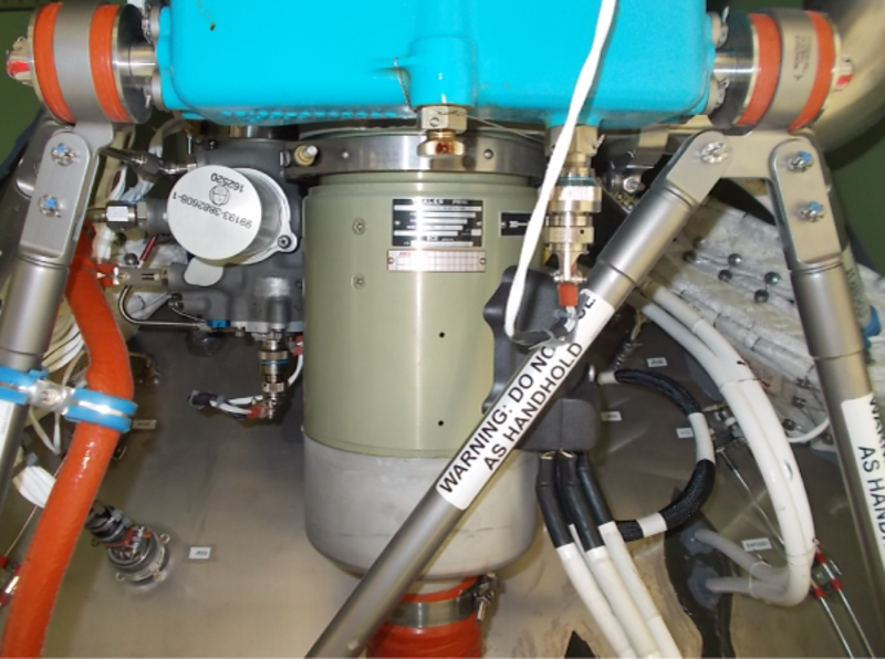
The main generators are installed on the accessory gearbox (AGB) of each engine via a quick attach/ detach (QAD) and V-band clamp to facilitate removal and replacement. The QAD incorporates an air outlet duct, which ducts the air overboard after it has passed through the generator.
The three stage brushless DC generators are identical, air-cooled (windings and rectifiers) with an integral fan, rated at 12 kVA, 400 amp (500 amp continuous overload) at a nominal 28.5 VDC and each is controlled by a dedicated GCU.
Two toroidal current transformers are mounted inside the generator and give an output current proportional to the DC generator output current. This is used by the GCUs for generator overload protection and to ensure load sharing during parallel operation of two (or three) DC generators. Two ball bearings lubricated with high temperature grease hold the rotor shaft, one at each end of the generator. The DC generators are provided with mechanical shear (887 in/lb) connection to protect the accessory gearbox (AGB) of the engine, a cooling air inlet, and connectors for interface with the electrical system. The main generators supply the electrical power to feed the aircraft loads under normal operation in flight and on ground when available.

APU Generator
The APU generator is installed on the gearbox of the APU and is identical to the main engine generators. The engine QAD and APU QAD are not identical. The APU generator can feed the loads on ground or in flight to replace an inoperative main generator. The APU generator is current-limited based on the APU performance and the bleed-air extraction at altitude.
With bleed-air extraction:
- 400 amp up to 15,000 ft
- 200 amp up to 20,000 ft
APU generator only:
- 400 amp up to 30,000 ft
- 300 amp up to 35,000 ft
Note:
If one main generator becomes defective, the APU generator, if available, connects to the main bus related to the defective generator. The APU generator connects to the L MAIN BUS through the left APU contactors 1 and 2 (LAPC1 and LAPC2). Also, it connects to the R MAIN BUS through the right APU contactors 1 and 2 (RAPC1 and RAPC2). The default bus for the APU generator is the right main bus when the two generators are available. The APU generator can operate in parallel with one or the two main generators.

Main Generator Control Unit
The generator control units (GCU) are printed circuit boards (PCB) located in the left and right DC power center (DCPC). They include two separated circuits. The first part contains the voltage regulator and current monitor and limit functions. The second part contains the fault protection, contactor control, and BIT functions.
There is one GCU for each main generator and all the GCUs are the same and fully interchangeable.
The GCU has the following main functions:
- Regulate the corresponding generator voltage at 28.5 VDC at generator speeds within the speed range 6,140 ±140 rpm to 13,665 rpm maximum
- Control the generator line contactor
- Protect generator and distribution system from; over-voltage, under-voltage, overload, and generator feeders fault differential
- Bus equalization (load sharing) during parallel operation of several DC generators
- Monitor and test the generation channel and its own circuits (BITE)

Auxiliary Generator Control Unit
As for the main generator, the auxiliary GCU (Aux GCU) is a PCB. It also includes two separated circuits, one for generator voltage control and one for GCU protection function. The auxiliary GCU is the same as the other GCUs, and they are fully interchangeable. This PCB is located in the Auxiliary DC power center (Aux DCPC).
For the APU, the auxiliary GCU supplies a low level control signal to the DCPC that controls the auxiliary power contactor (LAPC 2 and RAPC 2) and also controls the line contacting (LAPC 1 and RAPC 1). The APU and the main engine GCUs have a different speed threshold for the line contactor connection. This configuration is set through the GCU connector in the auxiliary DCPC to identify the APU channel.


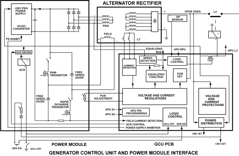
Main Generator Power Module
There is one power module for each main generator located in its related DCPC. The generator power modules are the same and supply a dedicated internal power supply for each DCPC.
The power module contains a rectifier circuit which takes AC voltage from the permanent magnet generator (PMG) of the generator and converts it into 25 VDC for use by the GCU, DCPC logic, and protection electronic PCBs.

Auxiliary Generator Power Module
The auxiliary generator power module supply is a dedicated internal power supply for the auxiliary DCPC. There is one auxiliary generator power module located in the auxiliary DCPC.
The power module contains a rectifier circuit which takes AC voltage from the PMG of the generator and converts it into 25 VDC for use by the GCU, DCPC logic,and protection electronic PCBs.

System Operation
Under normal operation, when the engines are running, the main generators are controlled automatically by the GCUs and each main generator supplies its related MAIN bus and ESSENTIAL bus. The left engine generator supplies the L MAIN BUS and the L ESS BUS. The right engine generator supplies the R MAIN BUS and the R ESS BUS. The generators can be disconnected from their buses manually by depressing the appropriate L GEN or R GEN PBA. Under certain conditions, automatic control from the GCU can be disabled using a toggle switch located on the secondary power centers (SPCs) circuit breaker panel.
For ground operation and flight preparation, power can be supplied by the APU generator or an external DC power source.
Note:
The APU generator can supply sufficient power to either main bus in the event of the loss of one main generator. It can serve as an alternative source of power in flight if one or both main generators become defective.
The operation of the DC power generation system is regulated and controlled by three dedicated GCUs. The three GCUs are identical. The GCUs provide voltage regulation, system protection and control.
The primary distribution of the generated power to the aircraft DC busses is done with a network of contactors. They are found in the left, right and auxiliary DCPC, located in the aft compartment.


System Monitoring
GCU Power Built-In Test
The GCU initiates power built-in test (PBIT) at power-up if power has been interrupted for more than 200 ms, on the ground only. PBIT is inhibited in flight.
If the test progress is not corrector if the test duration is too long, PBIT is stopped and a test failure is indicated. After completion of PBIT, the GCU indicates the success or failure of the PBIT to the appropriate DCPC.
During PBIT, all protection circuits and output signals to the DCPCs are verified.
GCU Continuous Built-In Test
The following GCU functions are monitored during continuous built-in test (CBIT):
- GCU fail-under-excitation and under-voltage over-voltage
- 28 VLPMG fuse
- 28 VESS fuse
- Logic discrepancy
- Regulation power supplies
- Protection power supplies
- GEN fail-under-voltage and over-excitation
- Over-ripple
- PMOD fail-power transistor failure
- PMG rectifier bridge (short circuit)
- GEN overload: > 500 amp
- GEN over-current: > 726 amp ±22 amp
If a failure is detected, the GCU indicates the failure to the appropriate DCPC.
The electrical power generation system can be monitored through the electrical control panel and a synoptic page on the multi-function displays (L/R MFD). A summary menu is also available for the following analog input:
- Left generator voltage
- Left generator current
- Right generator voltage
- Right generator current
- APU generator voltage
- APU generator current

08/28/23
Component Location Index
| Component Location Index | |||
|---|---|---|---|
| IDENT | DESCRIPTION | LOCATION | IPC REF |
| PL14 | ELECTRICAL CONTROL PANEL | ZONE(S) 210 | 24−31−01 |
| G1 | MAIN GENERATOR (LH) | ZONE(S) 432 | 24−31−05 |
| G2 | MAIN GENERATOR (RH) | ZONE(S) 442 | 24−31−05 |
| G3 | APU GENERATOR | ZONE(S) 320 | 24−31−09 |
| PCB5 | GENERATOR CONTROL UNIT (GCU) - PRIMARY (LH) | ZONE(S) 310 | 24−31−13 |
| PCB6 | GENERATOR CONTROL UNIT (GCU) -PRIMARY (RH) | ZONE(S) 310 | 24−31−13 |
| PCB9 | AUXILIARY GENERATOR CONTROL-UNIT | ZONE(S) 310 | 24−31−17 |
| PCB7 | GENERATOR POWER MODULE (LH) | ZONE(S) 310 | 24−31−21 |
| PCB8 | GENERATOR POWER MODULE (RH) | ZONE(S) 310 | 24−31−21 |
| PCB10 | AUXILIARY GENERATOR POWER MODULE | ZONE(S) 310 | 24−31−25 |