


11/16/15
Overview
There are three batteries in the battery system. They are identified as the left, right, and standby instrument battery. On the ground with no power source available, the left and right batteries provide 24 VDC power to all the electrical buses. This is accomplished when the respective left and/or right battery PBAs are pushed, via a network of contactors in the left, right, and auxiliary DCPCs. On the ground or in flight with the primary DC power source, the batteries are the backup source of electrical power for the essential buses and are charged using the main generators. In normal operation, the right battery also starts the auxiliary power unit (APU). If the right battery cannot start the APU, the left battery takes over automatically and starts the APU.
In an emergency, the left and right batteries and the standby instrument battery are used. The left and right batteries are the main source of electrical power,and the standby instrument battery gives electrical power to the integrated standby instrument (ISI) only. The main batteries are provided with vents and are identical and interchangeable. The standby instrument battery (ISI), is a charger and battery enclosed in one unit with a test function panel and LED for status monitoring. The maintenance test panel located on the right avionics rack also provides remote test functions of the ISI. The left and right batteries supply voltage and temperature information to the AFD via an interface connector and the electrical synoptic page.
Error messages related to the battery system are shown on the EICAS.

Main Batteries
There are two batteries. They are identified as the left battery and the right battery. The two batteries are installed in an unpressurized battery compartment between FS653.00 and FS680.00 in the belly fairing of the aircraft. For better battery performance, the battery compartment is thermally insulated and designed to receive vented air from the passenger cabin. Each battery is installed in a battery tray and held with two screw-down latches.
Each battery has a nominal output voltage of 24 VDC rated at 44 ampere-hours at the one hour discharge rate.
The batteries are twenty-cell nickel-cadmium low maintenance type. The twenty cells are replaceable and contained in a battery case and closed with a lid. The cells are connected in series with connector strips that attach to a quick-disconnect receptacle in one wall of the battery case.
The battery system has different electrical configurations. The configurations are set by the DCPC with weight-on-wheel (WOW) inputs from the PSEU. On the ground with no power source available, the left and right batteries provide 24 VDC electrical power to all the electrical busses. On the ground or in flight with a power source, the batteries are the backup source of electrical power for the left (L ESS BUS) and right (R ESS BUS) essential busses. In usual operation, the right battery is used to start the APU. But if the right battery is not serviceable, there are contactors in the LDCPC and RDCPC that will automatically switch to the left battery to start the APU.
In an in-flight emergency, the left battery gives electrical power to the L ESS BUS and the right battery gives electrical power to the R ESS BUS.
Temperature Sensors
Each battery has two internal temperature sensors. One is used for automatic overheat protection and the other one is used by the EICAS to monitor battery temperature. If the electrolyte temperature in a battery goes to 149°F (65°C), the battery sensor in the related DCPC will automatically disconnect it. The related battery contactor (left battery contactor LBATC or right battery contactor RBATC) is opened and latched and the charge to the battery is stopped.
The temperature sensors are internally connected to a bayonet-type connector on the front face of each battery. There are connectors from the aircraft harness that connect to these bayonet-type connectors. This connection gives the data to the related DCPC and the EICAS system for the monitoring and display of the battery temperature.


Harness Assemblies
The harness assemblies connects battery power from each battery to its related direct current power center (DCPC) for power distribution.
One end of the left harness assembly is connected to the left battery by the left battery power connector. The other end of the left harness assembly, the positive terminal is connected to the terminal stud of the left direct current power center (LDCPC). The negative of the terminal is connected to the left essential power ground stud.
One end of the right harness assembly is connected to the right battery by the right battery power connector. At other end of the right harness assembly, the positive terminal is connected to the terminal stud of the auxiliary direct current power center (Aux DCPC). The negative terminal is connected to the right essential power ground stud.


Protection Modules
There are two protection modules (PCBs) installed in the their respective DCPC and include the following functions:
- Internal power supplies
- Battery protection
- Feeder fault protection
- Bus fault protection (related to overload conditions of power sources)
- External DC power protection
- Electrical system built-in test functions
- Interface communication
These PCBs provide protection fort he following:
- Battery thermal runaway (greater than 60°C) through an overheat detection
- Battery feeder short circuit (greater than 400 amp) through a reverse current detection
- Battery overload (600 amp ±20 amp) through an overload detection
Note:
In any of the above conditions, the battery contactor is commanded opened and can be reset through the PBA. Additionally, if an overheat condition is detected (greater than 70°C) on the batteries and the contactor (L or R BATC) fails to open, a warning message is shown on EICAS.


Vent Tubes
Each battery has two vents. There are elbows and rubber vent tubes that connect to the two vents of each battery. The vent tubes are connected to the battery compartment vent system that is attached to the fuselage. The battery compartment vent system sends the hazardous gases from the battery compartment to the external air.


Standby Instrument Battery
There is one standby instrument battery (SIB) (also known as the ISI battery) In an emergency, it gives electrical power to the integrated standby instrument (ISI). The SIB can give electrical power to the ISI for 5.2 hours.
The SIB is installed in the nose landing gear bay area at FS227.50 in an unpressurized battery compartment. A battery compartment access panel with quick-release camlock fasteners gives access to the SIB. The SIB is installed in a tray and held with two hold-down screws. An electrical connector installed at the rear of the tray is the interface between the SIB and the wiring from the aircraft harness.
The SIB has an internal charger and heater. It contains two 12 V/13 Ah sealed-lead acid batteries with a 10.4 ampere-hours at the one hour discharge rate. The SIB does not have a vent.

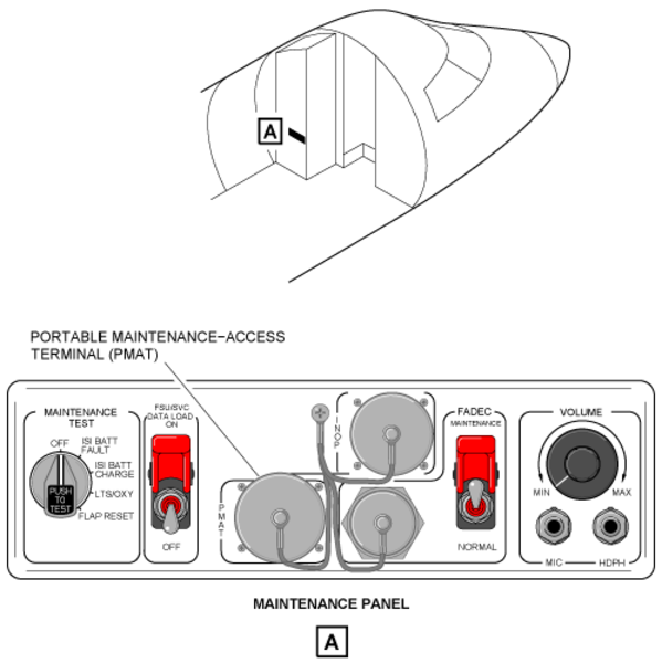
Maintenance Panel
There is one maintenance panel installed on the left equipment rack in the forward fuselage. On the maintenance panel there is a rotary test switch with two positions used to test the SIB. These positions are identified as ISI BATT FAULT and ISI CHARGE.
11/17/15
Operation
Main Batteries
The battery system is used to provide battery power on the ground, in flight and in emergencies. The battery system has interfaces with different components of the electrical system and has different electrical configurations on the ground and in flight. The configurations are set by the DCPC with weight-on-wheel (WOW) inputs from the PSEU and inputs from different systems. On the ground with no power source available, the left and right batteries provide 24 VDC electrical power to all the electrical busses. On the ground or in flight with a power source, the batteries are the backup source of electrical power for the L ESS BUS and R ESS BUS.
In an in-flight emergency (no engine or APU-driven generators available), the left battery and right battery give electrical power to the L ESS BUS and R ESS BUS only. And the SIB gives electrical power to the ISI.
In usual operation, a power diode in the SIB directs 28 VDC from the R ESS BUS (when available) to the ISI. If the 28 VDC from the R ESS BUS decreases below 24±1 VDC, the SIB automatically becomes the source of electrical power for the ISI.

Charge
Batteries
The left and right batteries do not have specific battery chargers. They are charged when external power, or engine or APU-driven generator power is available. Each battery is charged by a constant voltage source directly from its related essential bus. As long as the related battery contactor is closed and a generator or external power is connected to the aircraft's electrical busses, the batteries will continue to be charged.
When the batteries are connected to the constant voltage power source, they draw a high charge current. When they are close to their maximum charge condition, the batteries are only given a trickle charge of a few amps. To make sure there is a correct charge voltage, and prevent an overcharge and overheat condition, the output voltages of the power sources are regulated. The engine-driven or APU generator output voltage is regulated to 28.5 +/− 0.3 VDC. The external power is satisfactory if it is from 24.0 to 31.5 VDC.


Standby Instrument Battery
The SIB has an internal charger and a charge management system. The charge management system charges or prevents the charge of the SIB with the status of the electrical system. In usual operation, the SIB is charged by a 28 VDC internal charger. This internal charger is powered by 28 VDC from the R ESS BUS through circuit breaker CB2-C6.
On the ELECTRICAL control panel in the center pedestal, there is a STBY INST push button annunciator (PBA). This PBA has a black OFF legend. In usual operation the light in the PBA is not on and the charger and SIB are active. When it is pushed, the light in the PBA comes on which shows the OFF legend and the charger and SIB are not active. When the PBA is pushed again, the light in the PBA goes off and the charger and SIB are active again.
If all the generators fail and the only source of electrical power are the left and right batteries, the right DC power center (RDCPC) will inhibit the charge and heater functions of the SIB. This will prevent unnecessary depletion of the battery.
Interfaces
The battery system interfaces with the components that follow:
DCPC
The batteries are connected to the DCPCs (LDCPC and RDCPC) for primary power distribution.
All the power switching (contactors) and battery protection (battery sensors) is done by the control logic circuits on the printed circuit boards (PCBs) in the DCPCs.
The power distribution is related to the functions of the left bus tie contactor (LBTC) and the right bus tie contactor (RBTC). The operation of these contactors is controlled automatically by the DCPC logic functions. In the usual operation, the contactors are set to open (left and right side busses independent). When necessary, the contactors close to connect the left and right side busses to each other. The DCPC logic functions also use the weight-on-wheel (WOW) condition input that they receive from the PSEU, to set the necessary distribution configuration.
Also, the flight crew can set manually the bus tie contactors to open with the BUS TIE PBA found on the ELECTRICAL control panel. The BUS TIE PBA, when set to open, prevents automatic operation of the bus tie contactors (the white EICAS status message BUS TIE MAN OPEN shows). When the BUS TIE PBA is pushed again, the bus tie operation goes back to the automatic mode (the white EICAS status message BUS TIE MAN OPEN does not show).
SPC
The SPCs interface and work together with the DCPCs to give secondary power distribution and protection to different aircraft loads located in the forward section of the aircraft (loads that the flight crew do not have to access during flight). They have interfaces with the DCPCs and the EICAS for control and monitoring. The SPCs also mechanically connect the power available on the DCPC's distribution busses to the left and right cockpit circuit-breaker panel (LCBP and RCBP).
Aux DCPC
Because the right battery is used to start the APU, the Aux DCPC is used to supply power to the APU starting system. The Aux DCPC also gives protection against short circuits and the effects of unsatisfactory electrical-power quality.
The auxiliary-power start contactor (APSTC) in the Aux DCPC is used to connect electrical power to the APU starter motor (APU ST). The APU starter motor operates when the APSTC contactor is energized.
The right battery is the usual supply to the APU starter motor. However, if the right battery is not available, the left battery can be connected to supply the APU starter motor.
Note:
The operation of the APU starting system is the same when the aircraft is on ground or in flight.
In the usual configuration, the right battery is the starting source for the APU. The power from the right battery is supplied to the APU starter through the APSTC contactor.
When the right battery is used to start the APU, the logic functions of the electrical system make sure that the right battery is disconnected from the bus distribution system during the APU start operation. This is done to prevent current surges and so that the voltage on the busses does not decrease.
The left battery is used to start the APU when there is a fail condition in the right battery.
When the aircraft is in flight, if the two main generators are off-line and the right battery is not available, the power from the left battery is automatically supplied to the APU starter through the APSTC contactor. In this emergency condition, when an APU start command is given, the contactors in the LDCPC and RDCPC close automatically to let the APU start from the left battery.
When the aircraft is on the ground, if only the left main generator (L GEN) is on-line and the right battery is not available, the power from the left battery is automatically supplied to the APU starter through the APSTC. In this condition, when an APU start command is given, the contactors in the LDCPC and RDCPC close automatically to let the APU start from the left battery. During this type of APU start with the left battery, the voltage on the busses decreases because the left battery is not disconnected from the bus system.
Because the L GEN is on-line, it still supplies the busses and cross-starting occurs. This lets the L GEN help start the APU in parallel with the left battery.
Note:
When the aircraft is on the ground or in flight, if the two main generators are off-line, the LAUXC and RAUXC will be opened.
ISI
In an in-flight emergency (no engine or APU-driven generators available), the LDCPC, LSPC and the RDCPC and RSPC automatically let the left battery and right battery give electrical power to the L ESS BUS and R ESS BUS only. At this time, the standby instrument battery receives 24 VDC from the R ESS BUS through CB2-C6. And then to the ISI through the ELECTRICAL control panel.
Also at this time, the RDCPC inhibits the charger and heater functions of the standby instrument battery. This prevents unnecessary depletion of the battery.


02/01/16
Controls and Displays
Controls
The controls related to the battery system are the L BATT, R BATT, BUS TIE and STBY INST PBAs that are found on the ELECTRICAL control panel.
- The L BATT PBA lets the left battery be connected or disconnected from the L ESS BUS.
- The R BATT PBA lets the right battery be connected or disconnected from the R ESS BUS.
- The BUS TIE PBA lets the LBTC and the RBTC be manually connected or disconnected. In usual operation, these BTCs are in an automatic mode of operation.
If the BTCs are closed in this automatic mode, the light in the PBA comes on. When the BUS TIE PBA is pushed, the BTCs are manually opened and the light in the PBA goes off. When this is done the BUS TIE MAN OPEN message also shows on the EICAS.
When the PBA is pushed again, the BTCs are re-connected and go back to the automatic mode of operation. The light in the PBA comes on again and the BUS TIE MAN OPEN message does not show on the EICAS.
Note:
If the BTCs are not closed by the automatic mode, you cannot use the BUS TIE function to close them. This function only manually opens the BTCs and removes them from the automatic mode and closes them to let them go back to the automatic mode.
- The STBY INST PBA lets the SIB and its charger be connected or disconnected. In usual operation, the SIB and its charger are connected.
Displays
ELECTRICAL Synoptic Page
The ELECTRICAL synoptic page is a dynamic display that shows the current configuration of the electrical power distribution. The ELECTRICAL synoptic page shows analog and digital displays.
The DCPCs send monitoring data to the EICAS for display of the ELECTRICAL synoptic page, and when necessary, to show the applicable EICAS messages.
Analog Displays
The analog displays on the ELECTRICAL synoptic page include:
- Legends
- Power source outlines
- Primary bus outlines
- Flow-lines
The legends (APU, left GEN, right GEN, L BATT, R BATT, EXT PWR, L AUX BUS, R AUX BUS, L ESS BUS, R ESS BUS, L MAIN BUS, R MAIN BUS, BUS TIE with the dashes) show in grey. The generator outlines (left generator, right generator, and APU generator symbols) show in white (not in use), green (usual), amber (output less than 24.0 V or greater than 31.50 V).
The external power outline is blank (related source not connected), in white (related source connected but not used) or in green (output between 24.0 V and 31.5 V).
The battery outlines show in white (not used), green (usual), amber (temperature more than 65 °C and less than 70 °C), or red (temperature greater than 70 °C).
The primary bus outlines (L ESS BUS, R ESS BUS, L AUX BUS, R AUX BUS, L MAIN BUS, and R MAIN BUS) show in white (not in use), green (usual), or amber (bus voltage not greater than 10.0 V).
The flow-lines connect the power sources to the primary buses. The generator power lines show in white (not energized), or green (energized).
Digital Displays
The digital indications on the ELECTRICAL synoptic page are related to the functions that follow:
- Voltage monitoring
- Current monitoring
- Battery temperature monitoring.
The voltage monitoring function supplies:
- The voltage indication for the left, right, and APU generators. This indication is white (no voltage), green (usual), or amber (value less than 24 V or more than 31.5 V)
- The voltage indication for the left and right battery. This indication is green (usual), or amber (value less than 20 V)
- The voltage indication for the external power source. This indication is green (usual), or blank (source not connected and/or value not between 24.0 V and 31.5 V).
The current monitoring function supplies the current indication for the left, right, and APU generators. This indication is white (no current), green (usual), or amber (value greater than 500 A). The battery temperature monitoring supplies a temperature indication in degrees Celsius (°C), for each battery. This indication is green (temperature less than 65 °C), amber (temperature between 65 °C and 70 °C), or red (temperature greater than 70 °C).
The color of the digital indications changes to magenta dashes when the applicable data is not valid.

11/16/15
System Interface
The battery system has interfaces with the systems and components that follow:
- ELECTRICAL Control Panel
- DC Electrical-Load Distribution
- DC Power Center (DCPC) System
- Secondary Power Center (SPC) System
- Auxiliary DC Power Center (Aux DCPC) System
- Cockpit Circuit Breaker Panel (CCBP)
- Engine Indication and Crew Alerting System (EICAS)
- Electronic Flight-Instrument System (EFIS)
- Proximity-Sensor Electronic Unit (PSEU)
- Integrated Standby Instrument (ISI)
- Maintenance Diagnostic System.
11/16/15
System Monitoring
Main Batteries
Battery Overtemperature Protection
The left and right DCPCs monitor the associated battery temperature via a temperature sensor (thermistor) installed in the battery.
A battery overtemperature condition is detected if the battery temperature exceeds 65 ±2°C for greater than 50ms. In a battery overtemperature condition, the associated battery contactor opens and the battery disconnects from the essential bus.
The DCPC sends information to the EICAS indicating that the battery has disconnected and the associated BATT FAIL caution message is displayed The battery contactor latches in the tripped position and requires a single battery switch selection to reconnect the battery.
An additional temperature sensor(thermistor) is installed in the battery and provides an independent battery temperature monitor to the EICAS system.
The BATT OVERHEAT warning message is displayed on the CAS if:
- DCPC fails to detect the battery overtemperature condition and disconnects the battery
- Battery temperature exceeds 70±2°C
Battery Reverse Current Protection
Under normal operating conditions,the battery receives a charge current from the essential bus and a reverse current is present. The magnitude of this reverse current depends upon the state of charge and battery temperature.
A battery reverse current condition is detected if a reverse current of 400 ±20amp is detected for a period of at least 3 ±0.3 seconds. It is assumed that a short circuit exists in the battery feeder upstream of the battery contactor and the battery is disconnected from the essential bus. The battery contactor is latched in the tripped position and requires a single battery switch selection to reconnect the battery. The DCPC sends information to the EICAS, indicating that the battery has been disconnected and the associated BATT FAIL caution message is displayed.
ISI Battery Self Diagnostics
The ISI battery embodies a continuous built-in test (BIT) that ensures all essential functions are operational. If a fault is detected, a signal is immediately sent to the RDC and a STBY INST FAULT advisory message is subsequently posted on the EICAS.
EICAS Messages
The EICAS messages shown gives the related messages for the battery system: The L BATT OVERHEAT warning message shows when the internal temperature of the left battery is higher than 158°F (70 °C).
The R BATT OVERHEAT warning message shows when the internal temperature of the right battery is higher than 158°F (70 °C).
The BATT POWER ONLY warning message shows when the left and right engine and APU driven generators are off-line.
The L BATT FAIL caution message shows when the left battery has failed, or it has been automatically disconnected for overheat protection.
The R BATT FAIL caution message shows when the right battery has failed, or it has been automatically disconnected for overheat protection.
STBY INST BATT FAULT advisory message shows when:
- There is an overtemperature fault.
- There is a charger fault.
- There is a heater fault.
- There is a battery fault.
- The MAINTENANCE TEST rotary switch on the MAINTENANCE PANEL has been set to the ISI FAULT position.
The L BATT OFF status message shows when the L BATT PBA on the ELECTRICAL control panel has been set to OFF (pushed and PBA light comes on).
The R BATT OFF status message shows when the R BATT PBA on the ELECTRICAL control panel has been set to OFF (pushed and PBA light comes on).
The BUS TIE MAN OPEN status message shows when the BUS TIE PBA is pushed to manually open the bus tie and remove it from the automatic mode of operation.
The STBY INST OFF status message shows when STBY INST PBA on the ELECTRICAL control panel has been set to OFF (pushed and PBA light comes on).
| EICAS MESSAGES | LEVEL (COLOR) |
|---|---|
| L BATT OVERHEAT | WARNING (red) |
| R BATT OVERHEAT | WARNING (red) |
| BATT POWER ONLY | WARNING (red) |
| L BATT FAIL | CAUTION (amber) |
| R BATT FAIL | CAUTION (amber) |
| STBY INST BATT FAULT | ADVISORY (cyan) |
| L BATT OFF | STATUS (white) |
| R BATT OFF | STATUS (white) |
| BUS TIE MAN OPEN | STATUS (white) |
| STBY INST OFF | STATUS (white) |

System Test
Maintenance Panel Tests
There is one maintenance panel installed on the LH equipment rack in the forward fuselage. On the maintenance panel there is a rotary test switch. There are two positions on the panel used to test the SIB. These positions are identified as ISI BATT FAULT and ISI CHARGE.
ISI BATT Fault
This does a built-in-test (BIT) of the battery fault wiring. This test examines the function that activates the fault output line that checks the wiring between the SIB and the R ESS BUS.
To do the test, the rotary test switch of the maintenance panel is set to the ISI BATT FAULT position and pressed. After the rotary test switch is released, the test starts.
If the test is satisfactory, the STBY INST BATT FAULT advisory (cyan) message shows on the EICAS.
ISI BATT Charge
Note: Before this test is done and after every aircraft power-up, the ISI must be turned OFF (use STBY INST PBA of ELECTRICAL control panel). After the PBA is pressed, make sure the STBY INST OFF status message (white) is shown on the EICAS.
With the use of the maintenance panel, the maintenance diagnostic system (MDS) and the copilot multi-function display, maintenance personnel can do an energy level (capacity) test of the SIB. The SIB has a built-in internal test load across its two internal batteries. When the internal level test is done, the voltage is removed from the output terminals and connected to the internal test load. The pass/fail threshold is 80% of the rating marked on the nameplate of the SIB.
With the MDS and copilot MFD, choose the LRU INDEX page with the FILTER selection set to TESTABLE LRUS. To do the test, the rotary test switch of the FWD maintenance panel is set to the ISI BATT CHARGE position and pressed. After the rotary test switch is released, the SIB starts the test and the STBY INST BATT IN TEST message shows on the copilot multi-function display.
If the test is satisfactory, the STBY INST BATT TEST OK message shows on the copilot multi-function display. If the test is not satisfactory, the STBY INST BATT TEST FAIL message shows on the copilot multi-function display.
BIT
A BIT can be done with the BITE TEST pushbutton from the front panel of the SIB. The BIT checks the:
- Fault indicators (LED drive circuit)
- Front panel indicator
- Discrete monitor output signal
If the BIT is satisfactory the four LEDs that follow will flash every two minutes:
- BATT
- CHRG
- OTEMP
- HTR

