Overview
The emergency DC power system is used to supply electrical power, if the engine-driven generators are not available. Electrical power is supplied by the hydraulic motor-driven generator from the left or right main engine driven hydraulic power sources.

Hydraulic-Motor Driven Generator (HMDG)
The HMDG is installed, at the top of the left main landing gear(MLG) area, at FS482.36, WL67.88, and LBL 23.58. The HMDG motor is an axial piston, variable displacement hydraulic motor. The hydraulic motor has a maximum displacement of 0.13 in3 (2.13 cm3) per revolution. The hydraulic motor has a shaft speed of 10,800 rpm, and an overspeed limit of 15,625 rpm. The hydraulic motor is rated for a supply-side proof pressure of 4,650 psi (32,060.62kPa) and a burst pressure of 7,500 psi (51,710.68 kPa).
The HMDG generator is an air-cooled six-pole permanent magnet generator (PMG). It supplies five-stage AC power to a full wave bridge rectifier for conversion to a nominal 27.5 ±1.0 VDC power output. The HMDG stator includes an isolated, one phase AC output which is used by the GCU to sense speed. The DC output is rated at 2.9 kW continuous, 3.2 kW for five minutes, and 3.8 kW for five seconds. There is a short circuit capacity which is set to five seconds.
The right SPC (RSPC) supplies power from the R AUX BUS through CB4-B4 for the HMDG internal heating-element. The HMDG heater keeps the internal temperatures in the HMDG to above the dew point to prevent frost/ice. The PSEU supplies a weight-on-wheels (WOW) signal to a control relay found in the RSPC. The primary contacts of the control relay supply the power to the HMDG heater. The heater is on when the nose gear is up and locked and off when the nose gear is down and locked.

Ecology Bottle
An HMDG ecology bottle is isolated from the HMDG. The bottle is installed, in the middle bottom of the MLG area, at FS482.36. It is connected to the HMDG drain port by a flexible silicone tube. If there is too much fluid in the HMDG ecology bottle, it is sent overboard by a different flexible silicone tube.
The ecology bottles are made of environmental stress-crack-resistant (ESCR) plastic. The plastic is clear which lets the fluid quantity be seen when the bottle is closed and installed. The ecology bottle has a fluid capacity of 24 fluid oz. (709.76 mL).

Generator Control Unit (GCU)
A HMDG GCU is installed, in the lower nose fuselage area at FS293.20. The GCU is found at WL78.10 and LBL11.60. The GCU supplies all the necessary control, monitoring, protection, and BIT functions. The GCU has a printed wiring board (PWB), and does not contain a microprocessor.
The GCU senses and controls the DC voltage at the point of regulation (POR) of the HMDG. The POR is at the HMDG side of the line contactor (LC). The GCU changes the hydraulic motor's displacement in order to keep a nominal 27.5 ± 1.0 VDC power output.

Power Center
The HMDG power center (PC) is installed, in the aft compartment at FS685.40 from LBL4.10 to RBL1.60. The PC is used to distribute the additional source of electrical power supplied by the HMDG.

11/13/15
System Operation
The HMDG system supplies an emergency dc power-conversion from the left or right main engine driven hydraulic power sources. The system will operate when the engine-driven generators are not available.
The system is started when the pilot pushes the HMDG push-button-annunciator (PBA) on the ELECTRICAL control panel. This PBA has a black ON legend. In usual operation the light in the PBA is not on. When the PBA is pushed, the light in the PBA comes on which shows the ON legend and the HMDG is in operation. When the PBA is pushed again, the light in the PBA goes off and the HMDG is not in operation. The HMDG PBA starts the system when 28 VDC is connected to the solenoid-activated isolation valve in the HMDG. This usually closed valve supplies the hydraulic pressure to a servo valve in the HMDG and to the hydraulic motor.
If there is no hydraulic pressure, a spring keeps the hydraulic motor swash-plate in its full displacement position. When the isolation valve is open, it supplies hydraulic power to the motor, which gives full torque for maximum start-up acceleration. While the motor turns faster and approaches the speed for operation, the GCU senses the voltage made by the generator and starts a voltage control loop. The GCU moves the servo valve position, which controls the swash-plate angle. This controls the motor displacement which controls the motor output speed and torque to keep a 27.5 ± 1.0 VDC output.
A steady-state operation is related to the bus voltage. If the bus voltage is less than the GCU set point, the system will operate usually. HMDG speed is commanded by the GCU so the voltage at the point of regulation (POR) is kept at 27.5 ± 1.0 VDC. The POR is found on the HMDG side of the HMDG LC. The power priority is given by the rated nominal voltages of the different sources. The nominal voltage for the main generator is 28.5 ± 0.3 VDC. The nominal voltage for the HMDG is 27.5 ± 1.0 VDC and the nominal voltage for the battery is 24 VDC.

Electrical Generation
The GCU operates on a stable condition rate of input voltages from 18 to 29 VDC for emergency power operation. The RSPC supplies HMDG input power from the R ESS BUS through CB4-B5 to the GCU_TEST input. Power is also supplied for two different modes of operation. They are initiated BIT and HMDG operation.
For the initiated BIT power is sent through the HYD GEN rotary-switch on the MAINTENENCE TEST control-panel. During this mode no power is applied to the isolation valve.
For the HMDG operation power is sent through the HMDG PBA on the ELECTRICAL control panel. During this mode power is also applied to the isolation valve.
The POR sense input is used for voltage regulation functions only, unless loss of power occurs on the GCU_TEST input. If there is a voltage at the POR and loss of power occurs on the GCU_TEST input, the GCU continues to operate. The GCU operates from the power applied to the POR sense input.
The left hydraulic system supplies hydraulic power to the HMDG when the left engine-driven pump (EDP) is in operation. If the left EDP is not in operation, hydraulic power will be supplied by the right hydraulic system through the power transfer unit (PTU). The hydraulic pressure can be decreased to 1,670 psid (11,514.24 kPa) during PTU operation. This will cause a decreased electrical power performance (approximately 65 A DC at 28 VDC).
GCU Controls
The GCU has the following control functions:
HMDC LC Control
The GCU controls the HMDG LC contactor, and the contactor driver has short circuit protection. The HMDG LC is an electrically-held contactor. The HMDG LC is closed when:
The HMDG LC is closed when:
- The HMDG is set ON
- The POR voltage output is 27.5 ± 1.0 VDC
- No protection trip has occurred.
Servo Valve Control
The GCU controls the servo valve of the HMDG motor. This servo valve supplies a DC voltage output of 27.5 ± 1.0 VDC at the POR under normal conditions. The HMDG servo valve is externally electrically connected to the GCU and has short circuit protection.
Isolation Valve Control
The GCU supplies a usually open (non-conducting) return path for the isolation valve. When the HMDG is set ON and no protection trip has occurred, the return path is closed. The GCU senses the AC frequency and opens the return path when HMDG speed is more than the overspeed point.
POR Voltage Status
The GCU supplies the POR voltage signal to the RDC. This signal, supplied by a differential pair, is the DC POR voltage of the HMDG. The signals have short circuit protection by resistors internal to the GCU. The RDC supplies the status of the voltage to the ELECTRICAL SUMMARY and ELECTRICAL synoptic page of the EICAS.


Electrical Protective Functions
The HMDG system has protection functions. This is to prevent system damage and to make sure that the HMDG operates in the aircraft equipment power-quality-specification, MIL-STD-704E. The electrical protection functions are:
Over-voltage
The GUC can sense an over-voltage condition at the POR and open the HMDG LC and the isolation valve return-signal. This is done after a inverse time delay has occurred. The time delay uses the dropout time, for the HMDG LC. The GCU will make sure the HMDG LC and the isolation valve return-signal will be latched open after the trip. To close the latch the HMDG PBA is pushed.
Under-voltage
The GCU can sense an under-voltage condition at the POR and open the HMDG LC and the isolation valve return signal. This occurs after the fixed time delay of 2.75 ± 0.25 seconds. The under-voltage point is 19.5 ± 0.5 VDC. The GCU will make sure the HMDG LC and the isolation valve return-signal latched will be latched open after the trip. To close the latch the HMDG PBA is pushed.
Overspeed
The GCU can sense an overspeed condition of the HMDG and open the HMDG LC and the isolation valve return signal without a time delay. The overspeed point is 12,400 ± 150 rpm (620 ± 7.5 Hz). The GCU will make sure the HMDG LC and the isolation valve return-signal will be latched open after the trip. The GCU servo controls to the maximum current (minimum speed) if an overspeed condition occurs. To close the latch the HMDG PBA is pushed.
Underspeed
The GCU can sense an underspeed condition of the HMDG and open the HMDG LC without a time delay. The underspeed point is 2,400 ± 40 rpm (120 ± 2.0 Hz).
The GCU can close the HMDG LC if one of the causes of the underspeed is as follows:
- The GCU will automatically close the HMDG LC if the underspeed is due to a loss of input pressure
- The HMDG LC is latched open after the trip if the underspeed is due to being in parallel with the main generator. To close the latch the HMDG PBA is pushed.
System Fault Reset
The HMDG system can remove fault logic to let the pilot to put the HMDG system to its usual operation. The logic and protection functions will re-start when the system is reset. A reset is done as follows:
- The GCU is reset when the HMDG PBA on the ELECTRICAL control panel is pushed from the off position to the ON position
- The GCU automatically resets when DC voltage is applied at the power-up (during maintenance).
System Failsafe
The GCU has the capacity for a failsafe condition of the HMDG. A failsafe condition occurs when the GCU internal power-supplies are sensed out of range or if a defective logic clock is sensed. When the GCU goes into this failsafe mode, it opens the HMDG LC and the isolation valve return. It also moves the servo valve to the maximum current (minimum motor displacement).
Voltage Regulation and Current Sense
The GCU senses and regulates the DC voltage at the POR to 27.5 ± 1.0 VDC. The POR is at the HMDG side of the LC. The regulation voltage will be decreased if the hydraulic power is decreased at the HMDG motor, or the electrical output of the generator is decreased by the GCU.
The GCU has a current limit function to make sure that the generator current is decreased. A decrease in current occurs when a higher current than its continuous rating is necessary from the HMDG system for the batteries or aircraft loads. The GCU keeps 27.5 ± 1.0 VDC at the POR to a maximum current of 8.5 ± 5.0A DC. To decrease the generator power output the GCU reduces the regulation voltage when HMDG current is more than 8.5 ± 5.0A DC. This decreases the maximum generator current which prevents damage to the generator. This also makes sure that the 3.8 kW, 5 second rating of the generator is below the under-voltage point.

Displays
When the HMDG is set the HMDG and its electrical distribution lines are shown on the ELECTRICAL synoptic page of the EICAS. The legend HYD GEN, and the legend “ V” adjacent to the voltage digital readout are shown as half white. The line around the legend HYD GEN will change color with the conditions that follow:
| COLOR | CONDITION |
|---|---|
| Amber | Five seconds after the HMDG is set ON and the LC is still open, or the HMGG LC opens for more than five seconds during the initial 20 seconds after the HMDG is set ON, or the HMDG is set ON and the LC is open for at least 20 seconds |
| Green | The HMDG is set ON and the LC is closed and latched for 20 seconds, and the HMDG is set ON and the outline color is not amber |
| Magenta | The HMDG GCU voltage is valid, or the HMDG is set ON, or the HMDG LC is closed |
| White | The outline color is not green, and not amber, and not magenta |
When the HMDG is set a digital readout is shown on the ELECTRICAL synoptic page of the EICAS. When the line around the HYD GEN legend is amber or green the digital readout will be amber or green respectively. The digital readout will be magenta dashes or white with the conditions that follow:
| COLOR | CONDITION |
|---|---|
| Magenta - dashes | The HMDG GCU voltage is valid, or the HMDG is set ON, or the HMDG LC is closed |
| White | The readout color is not green, and not amber, and not magenta |
When the HMDG is set a HYD GEN output powerline is shown on the ELECTRICAL synoptic page of the EICAS. The HYD GEN output-power-line will change color with the conditions that follow:
| COLOR | CONDITION |
|---|---|
| Green | The HYD GEN outline is green and when the BUS TIE common powerline is green |
| Magenta | The HYD GEN outline is magenta |
| White | Not green and not magenta |
When the HMDG is set a legend is shown on the SUMMARY (ELECTRICAL) page of the EICAS. The legend is HYD GEN VOLTS and the legend is shown as half white. The digital readout adjacent to the legend HYD GEN VOLTS will change color with the conditions that follow:
| COLOR | CONDITION |
|---|---|
| Amber | Five seconds after the HMDG is set ON and the LC is still open, or the HMGG LC opens for more than five seconds during the initial 20 seconds after the HMDG is set ON, or the HMDG is set ON and the LC is open for at least 20 seconds |
| Green | The HMDG is set ON and the LC is closed and latched for 20 seconds, and the HMDG is set ON and the outline color is not amber |
| Magenta - dashes | The HMDG GCU voltage is valid, or the HMDG is set ON, or the HMDG LC is closed |
| White | The outline color is not green, and not amber, and not magenta |
When the HMDG is set a legend is shown on the HYDRAULIC synoptic page of the EICAS. The legend ELEC HYD GEN will change color with the conditions that follow:
| COLOR | CONDITION |
|---|---|
| White | Left Hydraulic System >1,800 psi or not hydraulic power transfer unit (PTU) low pressure |
| Amber | Left Hydraulic System ≤1,800 psi and hydraulic PTU low pressure |
| Magenta | Not white and not amber |
The ELEC HYD GEN FAIL caution message will show with one of the conditions that follow:
- In five seconds after the HMDG is set to ON and the HMDG LC is not closed
- When the HMDG LC opens for more than five seconds during the initial 20 seconds after the HMDG is set ON
- When the HMDG is set ON and the LC is open for at least 20 seconds
The ELEC HYD GEN ON status message will show when the HMDG is set ON and the main electrical power generators are not in operation to supply power to the aircraft loads.
Note: The ELEC HYD GEN ON status message will not show if the ELECT HYD GEN FAIL caution message is shown.
The EICAS messages that follow are related to the emergency DC-power system:
| EICAS MESSAGE(S) | LEVEL (COLOR) |
|---|---|
| ELEC HYD GEN FAIL | CAUTION (amber) |
| ELEC HYD GEN ON | STATUS (white) |

System Interface
The emergency DC-power system interfaces with the components that follow:
ELECTRICAL Control Panel
On the ELECTRICAL control panel in the center pedestal, there is a HYD GEN PBA. This PBA has a black ON legend. In usual operation the light in the PBA is not on. When the PBA is pushed, the light in the PBA comes on which shows the ON legend and the HMDG is on. When the PBA is pushed again, the light in the PBA goes off and the HMDG is not on.
RSPC
The RSPC supplies 28 VDC power from the R AUX BUS through circuit-breaker HYD GEN HTR (CB4-B4) for the HMDG internal heating-element. This power is also supplied to the PSEU for a WOW signal.
The RSPC also supplies HMDG input 28VDC power from the R ESS BUS through HYD GEN PWR/TEST (CB4-B5) to the GCU_TEST input. This power is supplied for two different modes of operation. They are the initiated BIT and the HMDG operation.
PSEU
The PSEU supplies a WOW signal to a control relay found in the RSPC. The main contacts of the control-relay supply power to the HMDG heater. The heater is on when the nose gear is up and locked and off when the nose gear is down and locked.
RDC
The RDC examines the HMDG operation and finds malfunctions. The GCU supplies two discrete signals which send its general condition and the status of the HMDG feeder at all times during operation. The GCU is supplied a nominal 28 VDC signal from the MAINTENANCE TEST control-panel. The GCU does the BIT and sends the results of the BIT to the RDC thru status signals. The position on the MAINTENANCE TEST control-panel used to do the HMDG generator test is identified as HYD GEN.


System Monitoring
Built-In Test (BIT)
The GCU has an BIT self-test capacity for maintenance functions. BIT examines the operation of the circuits and interfaces of the GCU. The GCU is supplied a nominal 28 VDC signal from the MAINTENANCE TEST control-panel. The GCU uses this signal to do BIT and send the results of the BIT to the RDC thru status signals.
A BIT can only be done when:
- The aircraft is on the ground
- The rotary switch on the MAINTENANCE TEST control-panel in the HYD GEN position
- The HMDG PBA on the ELECTRICAL control panel is not set ON.
The GCU supplies two discrete signals which send its general condition and the status of the HMDG feeder at all times during operation.
During initiated BIT:
- The GCU detects battery voltage at the POR when the HMDG LC contactor is closed, and there is an absence of battery voltage (the essential bus voltage is <19.5 ± 0.5 VDC) when the contactor is open. The GCU produces the applicable status on the HMDG FEEDER and the HMDG GCU signals.
- The GCU examines the input circuits to make sure GCU has interface integrity. The signals examined include the POR voltage sense, and the isolation valve driver-circuit. Confirmation of correct circuit operation is done and the applicable status on the HMDG GCU signal is issued.
- The GCU sends commands to the HMDG LC and starts the servo valve driver. The GCU senses the continuity of the servo valve coil and connected wiring. The RDC confirms the HMDG operation and finds malfunctions. Confirmation and valve driver operation is done and the applicable status on the HMDG FEEDER and the HMDG GCU signals are issued.
Test OK/TEST FAIL signals are started by the GCU in the time period for each BIT signal. The status output is an open circuit if BIT finds a malfunction. The status output is applicable during the BIT time period, and the status output is an open circuit after the BIT time period. The GCU does the BIT and sends the results of the BIT to the RDC thru status signals. The malfunctions that are isolated are:
- HMDG_GCU_TEST_OK/FAIL
- HMDG_FEEDER_TEST_OK/FAIL
- HMDG_LC TEST (The RDC reports the HMDG LC status by monitoring an auxiliary contact in the HMDG LC)
The HMDG FEEDER fault includes a partial check of the feeder. The GCU cannot detect an open feeder between the HMDG and the POR.
The BIT system does not examine the operation of the isolation valve or the servo valve. An operational test of the full emergency DC-power system is necessary. This is to examine the HMDGs mechanical system and the operation from the left and right hydraulic systems.

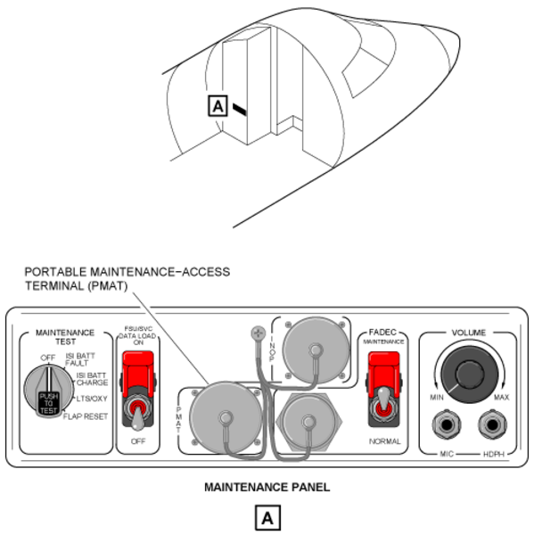
System Test
There is a MAINTENANCE TEST control-panel installed on the LH equipment rack in the forward fuselage. On the maintenance panel is a rotary test switch. The rotary switch position used for the HMDG generator test has the legend HYD GEN.