


11/13/15
Overview
The direct current (DC) power center (DCPC) system supplies the primary input and control functions for the aircraft electrical-power distribution.
The DCPC system includes power switching components, protection devices, and control logic circuits. With the functions of these components, the DCPC system:
- Makes the necessary connections between the power sources (DC generators, left and right batteries, and external power) and the aircraft loads
- Moves electrical power from the power sources to the secondary power centers (SPCs) and to loads in the aft section of the aircraft
- Gives protection against short circuits and effects of unsatisfactory electrical-power quality
- Controls the electrical distribution system, manually or automatically, when fault conditions occur
- Finds fault conditions of its components (built-in test (BIT)) and transmits the data for display in the flight compartment.
The DCPC system is supplied by the DC power sources that follow :
- Two main 28 VDC generators rated at 400 A (left generator and right generator)
- One auxiliary power unit (APU) 28 VDC generator rated at 400 A
- Two batteries rated at 44 Ah
- External DC power
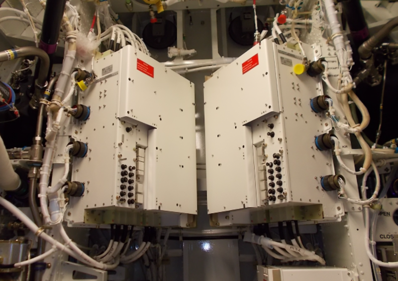
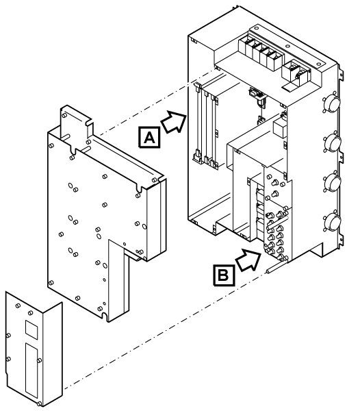
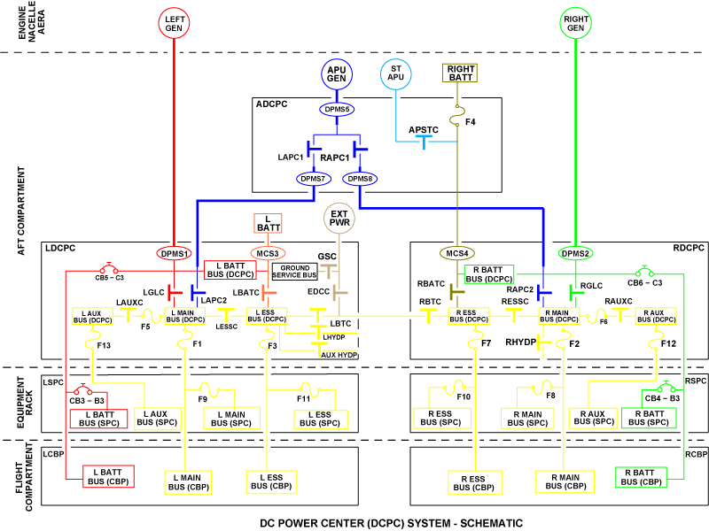
The DC power centers are electrical boxes that contain contactors, relays, and printed circuit boards (PCB). There are two DCPCs installed in the aft compartment of the aircraft. The DCPCs are supplied (directly or through the Aux DCPC) by the two main generators, the APU generator, the left and right batteries and the external power.
The primary function of the DCPC is to connect electrical power supplied by these power sources to the distribution busses and then to distribute this power to loads in the aft compartment, equipment racks, and flight compartment.
The DCPCs contain different components:
- Each DCPC contains a power module (PMOD) which changes voltage of the ac PMA into 25VDC that is used internally by the DCPCs
- Each DCPC contains logic and protection PCBs for control and protection of the primary distribution system
- Each DCPC contains contactors, busbars, current sensors, relays, fuses, and circuit breakers.
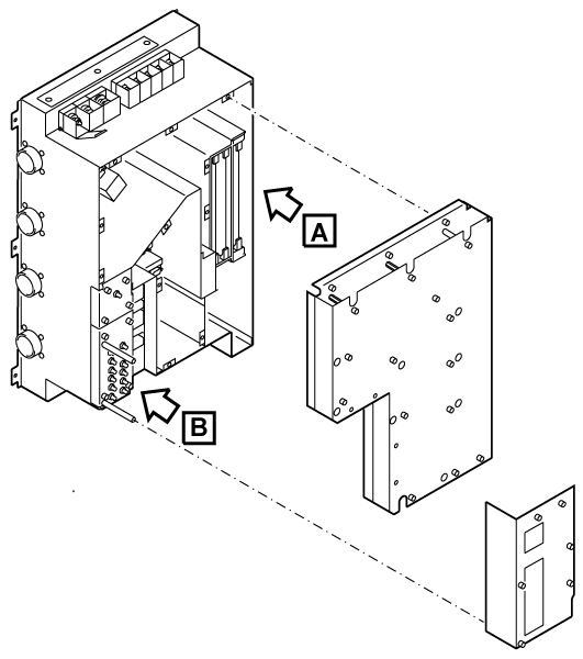
The DCPCs are made as follows:
- Each DCPC is made from aluminum sheet metal as a rigid box
- Each DCPC contains an epoxy baseplate which is along the full length and width of the box
- The contactors and current sensors are attached to the top surface of the baseplate
- The busbars are below the baseplate
- Relays and circuit breakers are all installed in their specific zones above the baseplate
- The electronic PCBs are installed in a metallic cage against an outer wall of the box, to give them protection against the effects of electromagnetic interference (EMI) and heat
- Physical separation between essential and non-essential functions, is given by walls which are along the full height of the box
- All electronic connectors are installed on the busbar side of the box. Connections to the electronic PCBs are made through a motherboard.

11/13/15
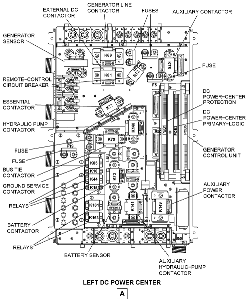
Left DC Power Center
The left DCPC contains the control, protection and distribution components for the left power generation and distribution system. These components include:
- Left generator control-unit (GCU)
- Right generator power-module
- Generator sensor (differential protection monitoring-sensor (DPMS1)) for the left generator feeder
- Left battery sensor (current monitoring sensor (MCS3))
- Right hydraulic-pump sensor (monitoring current sensor (R HYD MCS))
- Auxiliary hydraulic-pump sensor (monitoring current sensor (AUX HYD MCS))
- Remote-control circuit breaker (RCCB)
- Left-distribution logic control and protection electronics:
- DC power-center primary logic (PCB4)
- DC power-center protection (PCB2).
- Electronic components:
- Left-battery protection electronics
- External-power protection module
- Left secondary distribution-hardware
- Left communication electronics
- BIT electronics.
The LDCPC also includes different contactors, circuit breakers, fuses, and distribution busses.
LDCPC Contactors
The LDCPC has the contactors that follow:
- Left battery contactor (LBATC)
- Left generator line-contactor (LGLC)
- Left auxiliary-power contactor (LAPC2)
- External DC contactor (EDCC)
- Ground service contactor (GSC)
- Left auxiliary contactor (LAUXC)
- Left essential contactor (LESSC)
- Left bus-tie contactor (LBTC)
- Right hydraulic-pump contactor (RHYDP)
- Auxiliary hydraulic-pump contactor (AUXHYDP).
LDCPC Distribution Busses
The LDCPC supplies power to the LSPC and other loads through the electrical busses that follow:
- The left main bus (L MAIN BUS), on which are connected the primary loads
- The left essential bus (L ESS BUS), on which are connected the loads that are necessary for safety of flight during instrument meteorological condition operations
- The left battery bus (L BATT BUS), on which are connected the hot loads
- The left auxiliary bus (L AUX BUS), which is de-energized in flight when only one generator is available
- The ground service bus (supplied on ground by the external DC power), on which are connected loads used for servicing.


11/13/15
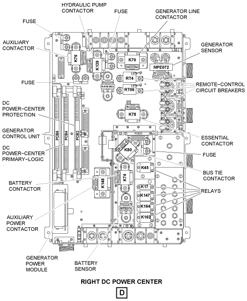
Right DC Power Center
The right DCPC contains the control, protection and distribution components for the right power generation and distribution system. These components include:
- Right generator control-unit (GCU)
- Right generator power-module
- Generator sensor (differential protection monitoring-sensor (DPMS2)) for the right generator feeder
- Right battery sensor (current monitoring sensor (MCS4))
- Left hydraulic-pump sensor (monitoring current sensor (L HYD MCS))
- Remote-control circuit breaker (RCCB)
- Right-distribution logic control and protection electronics:
- DC power-center primary logic (PCB3)
- DC power-center protection (PCB1).
- Electronic components:
- Right-battery protection electronics
- External-power protection module
- Right secondary distribution-hardware.
- Right communication electronics
- BIT electronics.
The RDCPC also includes different contactors, circuit breakers, fuses, and distribution busses.
RDCPC Contactors
The RDCPC has the contactors that follow:
- Right battery contactor (RBATC)
- Right generator-line contactor (RGLC)
- Right auxiliary-power contactor (RAPC2)
- Right auxiliary contactor (RAUXC)
- Left hydraulic-pump contactor (LHYDP)
- Right essential contactor (RESSC)
- Right bus-tie contactor (RBTC)
- Right auxiliary contactor (RAUXC).
RDCPC Distribution Busses
The RDCPC supplies power to the RSPC and other RDCPC loads through the electrical busses that follow:
- The right main bus (R MAIN BUS), on which are connected the primary loads
- The right essential bus (R ESS BUS), on which are connected the loads that are necessary for safety of flight during instrument meteorological condition operations
- The right battery bus (R BATT BUS), on which are connected the hot loads
- The right auxiliary bus (R AUX BUS), which is de-energized in flight when only one generator is available.


Contactors
The following contactors are all identical. They provide circuit connection for up to 400 amps and are capable of withstanding a generator output current of 500 amp continuous, 600 amp for 5 minutes and 800 amp for 5 seconds. They incorporate status contacts to report to the logic control of the DCPCs.
Battery Contactor
The function of the left and right battery contactors (LBATC and RBATC) is to connect the left battery to the left essential bus and the right battery to the right essential bus.
Generator Line Contactor
The function of the left and right generator line contactors (LGLC and RGLC) is to connect the left generator to the left main bus and the right generator to the right main bus.
Auxiliary Power Contactor
The function of the left and right auxiliary power contactors (LAPC2 and RAPC2) is to connect, through the auxiliary DCPC, the APU generator to the applicable left or right main bus.
External DC Contactor
The function of the external DC power contactor (EDCC) in the LDCPC only, is to connect the external DC power (EDCP) to the essential busses through the left and right bus-tie contactors (LBTC and RBTC).
Ground Service Contactor (GSC)
The function of the ground service contactor (GSC) in the LDCPC only, is to connect the external DC power (EDCP) to the ground service bus.
Auxiliary Contactor
The function of the left and right auxiliary contactors (LAUXC and RAUXC) is to connect the auxiliary buses to the main buses.
Essential Contactor
The function of the left and right essential contactors (LESSC and RESSC) is to connect the essential buses to the main buses.
Bus Tie Contactor
The function of the left and right bus-tie contactors (LBTC and RBTC) is to make the left and right essential busses connected to each other or disconnected from each other.
Hydraulic Pump Contactor
The function of the left and right hydraulic-pump contactors (LHYDP and RHYDP) is to connect the left essential bus and the right main bus to the applicable left or right hydraulic pump (DC motor-driven pump). The location of the RHYDP contactor (K140) is in left DCPC (LDCPC) and the location of LHYDP contactor (K139) is in right DCPC (RDCPC). Each hydraulic pump is controlled by the HYDRAULIC control panel through a protection PCB. The hydraulic pump contactors are reset with the circuit breakers that follow:
- CB1-C11 in the LCBP, for the right hydraulic-pump contactor
- CB2-C11 in the RCBP, for the right hydraulic-pump contactor
Auxiliary Hydraulic-Pump Contactors
The function of the auxiliary hydraulic-pump contactor (AUXHYDP) is to connect the left essential bus to the auxiliary hydraulic-pump (DC motor-driven pump) that is controlled by the HYDRAULIC control panel through a protection PCB. The auxiliary hydraulic-pump contactor can be reset with the CB1-D10 circuit breaker in the LCBP.


Remote Control Circuit Breaker
The remote control circuit breakers (RCCB) protect the main and essential buses against short circuits in the power line of the following systems:
- HF communication system No. 1 and No. 2
- Satellite communication (SATCOM) system
The DCPCs include the following RCCBs:
- One RCCB (RT3/K109) in the LDCPC for HF No. 1
- One RCCB (RT4/K108) in the RDCPC for HF No. 2
- One RCCB (RT06/K144) in the RDCPC for SATCOM
Each one of these three RCCBs supplies its function with one 80 ampere (A) contactor and one sensor (70 A time-delay thermal-detector). If too much load occurs (more than 70 A), the RCCB disconnects the applicable main or essential bus from the circuit which has an overload condition. The RCCBs are reset using the following circuit breakers:
- CB1-B3 in the LCBP, for the HF No. 1 RCCB
- CB2-B3 in the RCBP, for the HF No. 2 RCCB
- CB4-D2 in the RSPC, for the SATCOM RCCB

Remote Control Contactor
The remote control contactor (80 amp) provides protection for the main and essential buses against short circuits in the power line of the systems that follow:
- The avionics fan power is provided by two 80 amp contactors, one in each L and R DCPC (K154 and K9). These contactors are controlled by a 10 amp relay (K153 in the LDCPC), that monitors the AVIONIC FAN PWR circuit breaker (CB5-B2) on the left MAIN BUS. If the left main bus should de-energize, the 10 amp relay (K153) de-energizes and allows the right MAIN BUS to power the avionic fan.
Note:
The DCPCs and SPCs are provided with spare contactors for future growth. (80, 10, and 25 amp).

Current Sensors
Three types of current sensors are used in the DCPCs, differential protection monitoring sensors (DPMS) and monitoring current sensors (MCS).
Generator Sensor
The left and right generator sensors (DPMS) protect the left main bus against left generator overload and protect the right main bus against right generator overload. Differential protection monitoring sensors consist of a differential current sensor and a monitoring current sensor integrated into a single package.
For differential protection, a dedicated hall effect sensor continuously monitors the current imbalance between the two feeders. Each feeder is routed through a magnetic core of a hall effect sensor in opposition to each other such that the resultant field is zero with no current imbalance between the feeders.

Battery Sensor
The left and right battery sensors (MCS) prevent battery overcurrent or reverse current condition. Magnetic current sensors consist of a hall effect sensor sensing the field of a feeder or pair of feeders passing through a single magnetic core. The hall effect sensor produces a voltage signal proportional to the magnitude of the current (1mV per amp). This signal is used for current monitoring and overcurrent protection. They supply an automatic disconnect when the battery temperature gets to 65°C.

Hydraulic-Pump Monitoring Current Sensor
There are three hydraulic-pump monitoring current sensors (left, right, and auxiliary) connected to each DC motor-driven pump (left, right, and auxiliary). The hall effect sensor gives a voltage signal in proportion to the amount of the current (1mV per Amp). The signal is used for the current monitoring and overcurrent protection.

DC Power Center Primary Logic
The DC power center primary logic unit is a logic PCB installed in each DCPC (left and right). It supplies the control logic of the electrical system contactors. The logic PCB includes instructions for the functions that follow:
- Control of the primary distribution contactors (LGLC, LBATC, EDCC, LBTC, RBTC, LESSC, GSC, and LAUXC)
Note:
The left and right bus-tie contactors are fully controlled by the logic board. Both DCPCs, in relation with the system logical equation, control each L/R BTC.
A cross control is supplied between both logic PCBs for safety function. This cross control is validated by a DCPC fail condition signal which comes from the protection PCB of the side that has a fail condition.
- Discrete output control—EDC AVAIL (external DC power available)
- Power interface between external signals and contactors:
- APU starting contactor (APSTC)
- Hydraulic pump contactor
- Internal built-in test functions:
- Power-up built-in test (PBIT)
- Continuous built-in test (CBIT)
- Communication functions:
- Between logic PCB/protection PCB
- Between ELECTRICAL control panel/ DCPC

DC Power Center Protection
The DC power center protection unit is a protection PCB installed in each DCPC (left and right). It supplies the protection devices of the electrical system. The protection PCB includes the functions that follow:
- Internal power supplies:
- Protection power supply
- BIT power supply
- Battery protection:
- Battery reverse current detection
- Battery overload detection
- Overheat detection
- Feeder fault protections:
- Generator (main and APU) feeder protection
- APU bus-tie feeders protection
- Bus fault protection (related to overload conditions of power sources)
- External DC power protection
- Electrical system built-in test functions:
- Power-up built-in test (PBIT)
- Continuous built-in test (CBIT)
- Interface communication:
- Aeronautical Radio Inc. (ARINC) 429 interface
- Analog interface
- Discrete interface

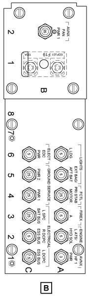
DC Power-Center Fuses
The DCPC fuses give protection for the cables that supply the buses in the circuit breaker panel. The fuses isolate the circuits which keep the effect of a wiring malfunction to a minimum. This prevents power loss to the other power users, supplied from the same power source.
A fire could occur if the supply of power to a circuit which has a malfunction is not isolated. The fuses isolate the circuit which keeps the risk of a fire to a minimum. The SPC fuses are used for a high electrical power load (more than 50 A).
There are five fuses in the left DCPC (LDCPC) and four fuses in the right DCPC (RDCPC). They are as follows:
- For the LDCPC: F1 (150 A), F3 (80 A), F13 (50 A), F5 (200 A), and F19 (100 A)
- For the RDCPC: F2 (150 A), F7 (80 A), F12 (150 A), and F6 (200 A).
If a fuse isolates a circuit the fuse can not directly cause a dangerous condition of operation. Thus a safe flight and landing can be done.
There is no access to the SPC fuses in flight because they are located in the avionics racks.

DC Power-Center Relays
There are two types of DCPC relays. They are the 2PDT (10 A) and the 3PDT (25 A).
There are six relays in the LDCPC and five relays in the RDCPC. They are as follows:
For the LDCPC:
- K83 (3PDT): the ground service contactor connects the external DC power to the ground service bus
- K16 (2PDT): the left landing gear light relay connects the left-main-bus power supply to the left landing gear switch
- K44 (3PDT): the motor control unit (MCU) relay connects the left-main-bus power supply to the MCU
- K153 (2PDT): the avionics cooling relay controls the K9 contactor to commute the left-main-bus power supply to the avionics fan
- K161 (3PDT): the left permanent magnet generator (LPMG) relay connects the left generator PMG voltage to the LDCPC PCB's when available
- K163 (3PDT): the auxiliary power unit (APU) PMG relay connects the APU generator PMG voltage to the LDCPC PCB's when available.
For the RDCPC:
- K45 (3PDT): the MCU relay connects the right-auxiliary-bus power supply to the horizontal-stabilizer-trim electronic-control unit (HST ECU)
- K17 (2PDT): the right landing gear light relay connects the right-main-bus power supply to the right landing gear switch
- K147 (3PDT): the baggage compartment relay connects the right-auxiliary-bus power supply to the cargo heater
- K164 (3PDT): the right permanent magnet generator (RPMG) relay connects the right generator PMG voltage to the RDCPC PCB's when available
- K162 (3PDT): the APU PMG relay connects the APU generator PMG voltage to the RDCPC PCB's when available.

11/17/15
System Operation
Power Distribution Logic
As shown on the power-distribution logic table, the electrical system operates with a combination of the different power sources that follow:
- Left generator (L GEN)
- Right generator (R GEN)
- Left battery (L BATT)
- Right battery (R BATT)
- APU generator (APU GEN).
The DCPC system uses its internal logic functions and the data it receives from the power sources and other aircraft systems to set a specific power-distribution configuration.
The DCPCs receive manual inputs from the ELECTRICAL control panel to set/change the different operation configurations. These operation configurations change automatically in relation to the command inputs.
Each operation configuration is related to:
- The operation status of the power sources (available or not available)
- The conditions of the distribution busses (usual or unusual)
- The aircraft configuration (in flight or on ground).
In usual operation, each side of the electrical system operates independently:
- The left main generator supplies electrical power to energize the busses of the left side electrical system
- The right main generator supplies electrical power to energize the busses of the right side electrical system
- The left battery connects to the L ESS BUS to charge from the left main generator
- The right battery connects to the R ESS BUS to charge from the right main generator.
The APU generator can be connected in parallel with one of the engine generators. By default, the APU generator connects to the right main bus, except when it replaces an inoperative engine generator. In this condition, the APU generator connects to the side that has the inoperative generator.
Also, when the aircraft is on ground, external DC power source can be connected to the aircraft to supply all loads.
The external source of DC power is connected to the aircraft through a DC power receptacle located in the external-power control panel, at the rear of the aircraft.
The sections that will follow give a description of configurations that operate with:
- Three generators as power sources (L GEN, R GEN, and APU GEN)
- Two main generators as power sources (L GEN and R GEN)
- One main generator and the APU generator as power sources:
- L GEN and APU GEN
- R GEN and APU GEN
- One generator as power source (L GEN, R GEN, or APU GEN)
- Batteries only as power sources (L BATT and R BATT)
- External power as power source (EXT PWR)
- APU starting system.
Note: In the different configuration illustrations that will follow, LAPC and RAPC contactor symbols represent the operation of LAPC1/LAPC2 contactors and RAPC1/RPAPC2 contactors respectively. These contactors are controlled by the APU GCU and the Aux DCPC.

L GEN, R GEN, and APU GEN
Aircraft on Ground or in Flight
In this configuration, each generator supplies its own bus:
- The left engine generator (L GEN) supplies the L MAIN BUS
- The right engine generator (R GEN) supplies the R MAIN BUS.
An additional generator power source is available from the APU. When the APU generator is set to ON (with the APU GEN PBA on the ELECTRICAL control panel), it connects in parallel with the right generator into the R MAIN BUS only. In this configuration, the APU generator will replace an engine generator that becomes unavailable.
The batteries connect to the essential busses: L BATT connects to L ESS BUS and R BATT connects to R ESS BUS.
Also, L ESS BUS connects to L MAIN BUS and R ESS BUS connects to R MAIN BUS, which therefore supplies the charging function for the batteries.
L MAIN BUS and R MAIN BUS are physically and electrically separated from each other and the routing of supplies to the distribution busses through separate control centers, LDCPC and RDCPC respectively for the L MAIN BUS and the R MAIN BUS.
With L GEN, R GEN, and APU GEN as power sources,
- LBATC and RBATC are closed to let the batteries charge from their applicable left or right essential bus
- LBTC and RBTC are open to let the left and right side systems operate independently
- if a fail condition occurs in the left generator, RAPC will open and LAPC will close to let the APU generator supply the left side busses.

L GEN and R GEN
Aircraft on Ground or in Flight
This configuration is set if the APU GEN is not available. The configuration is similar to the usual operation described above, but the power is supplied by the two engine driven generators only. In this configuration, the APU generator cannot replace an engine generator.
With L GEN and R GEN as power sources:
- LBATC and RBATC are closed to let the batteries charge from their applicable left or right main generator
- LBTC and RBTC are open to let the left and right sides operate independently.

L GEN and APU GEN
Aircraft on Ground or in Flight
When the APU generator is on-line, it replaces automatically a generator that becomes unavailable.
If the R GEN becomes unavailable, RGLC opens to isolate the right generator and the APU will automatically supply electrical power to the right side busses through RAPC.

R GEN and APU GEN
Aircraft on Ground or in Flight
When the APU generator is on-line, it replaces automatically a generator that becomes unavailable.
If the L GEN becomes unavailable, LGLC opens to isolate the left generator. In this condition, RAPC will open and LAPC will close to let the APU automatically supply electrical power to the left side busses.

L GEN
Aircraft on Ground
If RH GEN and APU GEN are not available, the bus-tie contactors (LBTC and RBTC) close automatically and the system will be set to a configuration that lets the LH generator supply the two main busses. On ground, the auxiliary busses stay energized through the auxiliary contactors (LAUXC and RAUXC open).
Aircraft in Flight
If RH GEN and APU GEN are not available, the bus tie contactors (LBTC and RBTC) close automatically and the system will be set to a configuration that lets the LH generator supply the two main busses. In flight, the auxiliary busses will be disconnected (LAUXC and RAUXC open). With L GEN as power source, LBATC and RBATC are closed to let the batteries charge from the left side generator.


R GEN
Aircraft on Ground
If LH GEN and APU GEN are not available, the bus-tie contactors (LBTC and RBTC) close automatically and the system will be set to a configuration that lets the RH generator supply the two main busses. On the ground, the auxiliary busses stay energized through the auxiliary contactors (LAUXC and RAUXC closed).
Aircraft in Flight
If LH GEN and APU GEN are not available, the bus-tie contactors (LBTC and RBTC) close automatically and the system will be set to a configuration that lets the RH generator supply the two main busses.
In flight, the auxiliary busses will be disconnected (LAUXC and RAUXC open). With R GEN as power source, LBATC and RBATC are closed to let the batteries charge from the right side generator.


APU GEN
In this configuration the APU generator is the only generator power source. By default, the APU generator connects to the right main bus through RAPC and supplies the left side system through the bus tie contactors. In usual conditions, with APU GEN as the only power source, LBATC and RBATC are closed to let the batteries charge from the APU generator.
If there is fail condition in this configuration, the logic functions of the electrical system do a fault isolation and, if necessary, they send commands to change the configuration. In relation to the fault isolation result, the APU GEN can be automatically connected to supply its power through LAPC and RAPC or through LAPC only.
Aircraft on Ground
On the ground, the APU generator connects to the right busses and the bus tie contactors (LBTC and RBTC) close automatically to make sure that the left side busses are supplied from the APU generator.
In this configuration, the auxiliary busses are energized (LAUXC and RAUXC closed).
Aircraft in Flight
In flight, the APU generator connects to the right busses through the bus tie contactors (LBTC and RBTC closed) as on the ground. In this condition however, the auxiliary busses will not be energized (LAUXC and RAUXC contactors open).


L BATT and R BATT
In this configuration the batteries are the only power source. With L BATT and R BATT as power sources, on ground or in flight, the bus tie contactors (LBTC and RBTC) are closed to let the batteries supply in parallel the left and right side busses.
Aircraft on Ground
On ground, the batteries will supply in parallel all the busses (the bus tie contactors and the LAUXC, LESSC, RESSC, and RAUXC contactors are closed).
Aircraft in Flight
In the in-flight emergency condition, the batteries supply the essential busses only. The L BATT connects to the L ESS BUS and the R BATT connects to the R ESS BUS. The bus tie contactors are closed but the LAUXC, LESSC, RESSC, and RAUXC contactors are open to let the batteries supply the L ESS BUS and R ESS BUS only.
In this configuration, only important loads are supplied with electrical power, so that the system operation stays safe in conditions of limited power. These loads include primary control systems and safety systems, and navigation and communication systems (these are sufficient to give safe flight and landing in instrument meteorological conditions). Load connection to the essential bus is limited to enable emergency flight-time duration of one hour minimum.


EXT PWR
Aircraft on Ground
In the external DC power source configuration, all the busses are supplied by the external DC power source.
To let the external power supply the aircraft, it is necessary to push the EXT PWR PBA on the ELECTRICAL control panel. This selection is inhibited if one or more generators are on line. The generators come offline if the EXT PWR PBA is pushed on the ELECTRICAL control panel. When ground power is connected to the aircraft, the batteries will charge from this source.
With external DC power (EXT PWR) as power source,
- LBTC and RBTC are closed to let the DC power source supply the left and right side busses
- LBATC and RBATC will close only if the external DC power is satisfactory (between 24.0 and 31.5 VDC).

APU Starting System
Aircraft on Ground or in Flight
The right battery is the usual supply to the APU starter motor (APU ST). When R BATT is the APU starting source, the RBATC contactor disconnects the battery from the bus distribution system to prevent current surges and voltage drops on busses.
In the event that the right battery is not available, the left battery is used to supply the APU starter. The left battery as the APU starting source is an unusual configuration caused by a fail condition in the right battery.
In usual condition, LBATC is closed to let the left battery charge from the left main generator. If the right battery becomes unavailable and there is an APU start command, LBTC, RBTC and RBATC contactors will automatically close to let the APU start from the left battery.
When the APU starter motor is supplied from the left battery, the voltage on the busses will decrease, because the L BATT is not disconnected from the bus system. Also, if it is necessary to use the left battery for APU starting and a generator is on line, a cross-starting will occur, which makes the generator help the start operation in parallel with the battery.

11/13/15
Controls and Displays
The operating status of the different power sources shows on the related pushbutton annunciators (PBAs) found on the ELECTRICAL control panel. These PBAs have applicable ON, OFF, or AVAIL/ON legends and related lights that are off in the usual operation conditions.
To set a power source to ON or OFF status as applicable, the related PBA must be pushed. The PBA light comes on to show the applicable legend. To set the power source to the previous status, the PBA is pushed one time again.
The power distribution is related to the functions of the bus tie contactors (LBTC and RBTC). The operation of these contactors is controlled automatically by the DCPC logic functions. In the usual operation, the contactors are set to open (left and right side busses independent). When necessary, the contactors close to connect the left and right side busses to each other. The DCPC logic functions also use the weight-on-wheel (WOW) condition input that they receive from the PSEU, to set the necessary distribution configuration.
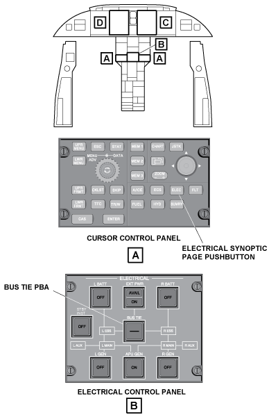
Also, the flight crew can set manually the bus tie contactors to open with the BUS TIE PBA found on the ELECTRICAL control panel. The BUS TIE PBA, when set to open, prevents automatic operation of the bus tie contactors (in this condition, the EICAS message BUS TIE MAN OPEN shows). When the BUS TIE PBA is pushed again, the bus tie operation goes back to the automatic mode. The light of the BUS TIE PBA comes on when the bus tie contactors are in the closed position and goes off when these two contactors are in the open position.
The DCPCs send monitoring data to the EICAS for display of the ELECTRICAL synoptic page, and when necessary, to show the applicable EICAS messages. The ELEC pushbutton on the cursor control panel (CCP), if pushed, will show the ELECTRICAL synoptic page on the lower half of the multi-function display (MFD).
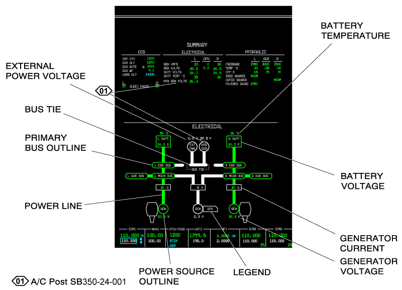
ELECTRICAL Synoptic Page
The ELECTRICAL synoptic page is a dynamic display that shows the current configuration of the electrical power distribution on the MFD. The ELECTRICAL synoptic page shows analog and digital displays.
Note: The display related to the external DC power is a pop-up display and is only shown on ground when external power is connected to the aircraft.
Analog Displays
The analog displays on the ELECTRICAL synoptic page include:
- Legends
- Power source outlines
- Primary bus outlines
- Power lines.
The legends (APU, left GEN, right GEN, L BATT, R BATT, EXT PWR, L AUX BUS, R AUX BUS, L ESS BUS, R ESS BUS, L MAIN BUS, R MAIN BUS, BUS TIE with the dashes) show in grey.
The generator outlines (left generator, right generator, and APU generator symbols) show in one of the colors that follow:
- White (generator not used)
- Green (usual operation)
- Amber (output less than 24.0 V or greater than 31.50 V).
The external power outline is blank (related source not connected), in white (related source connected but not used) or in green (output between 24.0 V and 31.5 V).
The battery outlines show in white (not used), green (usual), amber (temperature more than 65°C and less than 70°C), or red (temperature greater than 70°C).
The primary bus outlines (L ESS BUS, R ESS BUS, L AUX BUS, R AUX BUS, L MAIN BUS, and R MAIN BUS) show in white (not used), green (usual), or amber (bus voltage not greater than 10.0 V)
The power lines connect the power sources to the primary busses. The generator power lines show in white (not energized), or green (energized). When the external power source is connected to the aircraft, the external-source power line is white (not energized) or green (energized).
Digital Displays
The digital indications on the ELECTRICAL synoptic page are related to the functions that follow:
- Voltage monitoring
- Current monitoring
- Battery temperature monitoring.
The voltage monitoring function supplies:
- The voltage indication for the left, right, and APU generators. This indication is white (no voltage), green (usual), or amber (value less than 24 V or more than 31.5 V)
- The voltage indication for the left and right battery. This indication is green (usual), or amber (value less than 20 V)
- The voltage indication for the external power source. This indication is green (usual), or blank (source not connected and/or value not between 24.0 V and 31.5 V).
The current monitoring function supplies the current indication for the left, right, and APU generators. This indication is white (no current), green (usual), or amber (value greater than 500 A).
The battery temperature monitoring supplies a temperature indication for each battery. This indication is green (temperature less than 65°C), amber (temperature between 65°C and 70°C), or red (temperature greater than 70°C).
The color of the digital indications changes to magenta dashes when the applicable data is not valid.
EICAS Messages
The EICAS uses inputs from the DCPCs and other systems to supply the logic equations for the CAS messages of the electrical system.
Inputs from other systems to the EICAS include the WOW condition and the operation status of the left engine, right engine, and APU.
Warning Messages
Warning messages (red) tell the flight crew that:
- The applicable left or right battery internal temperature is greater than 70°C (L (R) BATT OVERHEAT warning).
- The engine and APU driven generators are off and the only electrical power available is from the batteries (BATTERY POWER ONLY warning)
Caution Messages
Caution messages (amber) tell the flight crew that:
- The applicable generator source (left, right, or APU generator) has a fail condition (voltage not between 24.0 V and 31.0 V) (L (R) (APU) GEN FAIL caution messages)
- The applicable left or right battery has fail condition, or the battery contactor has a fail condition, or the battery has been automatically disconnected for overheat protection (L (R) BATT FAIL caution messages)
- The applicable generator (left, right, or APU generator) has fail condition (generator current greater than 500 A and less than 700 A) (L (R) (APU) GEN OVERLOAD caution messages)
- The applicable left or right main or essential bus is not energized with a power source that is available (L (R) MAIN BUS FAIL, L (R) ESS BUS FAIL caution messages)
- The electrical system has a fail condition that causes the loss of the electrical indications display (ELECTRICAL FAULT caution message).
Advisory Messages
Advisory messages (cyan) tell the flight crew that:
- The applicable left or right auxiliary bus is not energized with a power source that is available (L (R) AUX BUS FAIL advisory messages)
- The electrical system has a fault that causes the loss of redundancy in the display of electrical indications (ELECTRICAL FAULT advisory message).
Status Messages
Status messages (white) tell the flight crew that:
- The applicable power source (left, right, or APU generator, left or right battery) has been manually set off (L (R) (APU) GEN OFF, L (R) BAT OFF status messages)
- The bus tie has been manually set open (BUS TIE MAN OPEN status message).
The EICAS messages that follow are related to the DCPC system:
| EICAS MESSAGES | LEVEL (COLOR) |
|---|---|
| L BATT OVERHEAT | WARNING (red) |
| R BATT OVERHEAT | WARNING (red) |
| BATT POWER ONLY | WARNING (red) |
| APU GEN FAIL | CAUTION (amber) |
| APU GEN OVERLOAD | CAUTION (amber) |
| L BATT FAIL | CAUTION (amber) |
| R BATT FAIL | CAUTION (amber) |
| ELECTRICAL FAULT | CAUTION (amber) |
| L ESS BUS FAIL | CAUTION (amber) |
| R ESS BUS FAIL | CAUTION (amber) |
| L GEN FAIL | CAUTION (amber) |
| R GEN FAIL | CAUTION (amber) |
| L GEN OVERLOAD | CAUTION (amber) |
| R GEN OVERLOAD | CAUTION (amber) |
| L MAIN BUS FAIL | CAUTION (amber) |
| R MAIN BUS FAIL | CAUTION (amber) |
| L AUX BUS FAIL | ADVISORY (cyan) |
| R AUX BUS FAIL | ADVISORY (cyan) |
| ELECTRICAL FAULT | ADVISORY (cyan) |
| APU GEN OFF | STATUS (white) |
| L BATT OFF | STATUS (white) |
| R BATT OFF | STATUS (white) |
| BUS TIE MAN OPEN | STATUS (white) |
| L GEN OFF | STATUS (white) |
| R GEN OFF | STATUS (white) |

System Interface
The DCPC has interfaces with the different power sources and loads. The DCPCs receive DC electrical power from the power sources and use their logic functions to open/close, as applicable, the DCPC contactors to supply the necessary primary electrical distribution.
Left DCPC Interfaces
The LDCPC receives DC electrical power from:
- The left generator, through the LGLC contactor
- The left battery, through the LBATC contactor
- The APU generator, through the LAPC2 contactor (and the LAPC1 contactor in the Aux DCPC)
- The external DC power source, through the EDCC and LBTC contactors.
The electrical power from the power sources is supplied to the LDCPC busses (L MAIN BUS, L ESS BUS, L AUX BUS, and L BATT BUS) through the applicable LDCPC contactors (LESSC, LAUXC, and LBTC).
The LDCPC busses supply the electrical distribution as follows:
- The left main bus in the LDCPC supplies power to the left main bus in the left secondary power center (LSPC) and to the left main bus in the left circuit-breaker panel (LCBP)
- The left essential bus in the LDCPC supplies power to:
- The left essential bus in the LSPC
- The left essential bus in the LCBP
- The right and auxiliary hydraulic pumps (through the RHYDP and AUX HYDP contactors).
- The left auxiliary bus in the LDCPC supplies power to the left auxiliary bus in the LSPC
- The left battery bus in the LDCPC supplies power (through CB5-C3 circuit breaker) to the left battery bus in the LSPC and to the left battery bus in the LCBP
- The external DC power is supplied to the ground service bus through the GSC contactor.
Right DCPC Interfaces
The RDCPC receives DC electrical power from:
- The right generator, through the RGLC contactor
- The right battery, through the RBATC contactor
- The APU generator, through the RAPC2 contactor (and the RAPC1 contactor in the Aux DCPC)
- The external DC power source, through the EDCC and RBTC contactors.
The electrical power from the power sources is supplied to the RDCPC busses (R MAIN BUS, R ESS BUS, R AUX BUS, and R BATT BUS) through the applicable RDCPC contactors (RESSC, RAUXC, and RBTC).
The RDCPC busses supply the electrical distribution as follows:
- The right main bus in the RDCPC supplies power to:
- The right main bus in the right secondary power-center (RSPC)
- The right main bus in the in right circuit-breaker panel (RCBP)
- The left auxiliary hydraulic-pump (through the LHYDP contactor).
- The right essential bus in the RDCPC supplies power to:
- The right essential bus in the RSPC
- The right essential bus in the RCBP.
- The right auxiliary bus in the RDCPC supplies power to the right auxiliary bus in the RSPC
- The right battery bus in the RDCPC supplies power (through CB6-C3 circuit breaker) to the right battery bus in the RSPC and to the right battery bus in the RCBP.
System Monitoring
The flight crew monitors the electrical system operation through the ELECTRICAL synoptic page on the MFD, the CAS messages, and the status of the PBAs located on the ELECTRICAL control panel and on the external-power control panel.
The DCPCs use their internal BIT functions (PBIT and CBIT) and also the signals they receive from different components of the electrical system to supply the monitoring data to the EICAS.
The DCPC system receives voltage and current inputs from the L GEN, R GEN, EXT POWER, L BATT, and the R BATT systems and send the related data (in ARINC 429 format and analog format) to the EICAS for display on the ELECTRICAL synoptic page. The other monitoring data shown on the ELECTRICAL synoptic page are supplied to the EICAS through:
- The Aux DCPC system, for the APU GEN voltage and current
- The SPC system, for the voltage on the primary busses (L ESS BUS, L MAIN BUS, L AUX BUS, L BATT BUS, R ESS BUS, R MAIN BUS, R AUX BUS, and R BATT BUS)
- The battery system, for the L BATT and R BATT temperature.
System Test
The electrical system has built-in test (BIT) functions that supply status of the electrical system. They include the BIT function for the logic and protection circuits of the left and right DCPC. This BIT includes a power-up BIT (PBIT) and a continuous BIT (CBIT).
The PBIT operates on ground only and for a maximum of 0.5 seconds. The PBIT test is inhibited in flight.
The CBIT starts immediately after the PBIT has completed. The CBIT operates continuously as long as the system is energized.
If the BIT tests find a fail condition, the DCPC sends an applicable data to the EICAS and to the MDC.
10/16/20
Component Location Index
| Component Location Index | |||
|---|---|---|---|
| IDENT | DESCRIPTION | LOCATION | IPC REF |
| A35 | DC POWER CENTER (DCPC) (LH) | ZONE(S) 311 | 24-61-01 |
| A36 | DC POWER CENTER (DCPC) (RH) | ZONE(S) 312 | 24-61-01 |
| K73 | BATTERY CONTACTOR (LH) | ZONE(S) 311 | 24-61-05 |
| K74 | BATTERY CONTACTOR (RH) | ZONE(S) 312 | 24-61-05 |
| K69 | GENERATOR LINE CONTACTOR (LH) | ZONE(S) 311 | 24-61-09 |
| K70 | GENERATOR LINE CONTACTOR (RH) | ZONE(S) 312 | 24-61-09 |
| K149 | AUXILIARY POWER CONTACTOR (LH) | ZONE(S) 311 | 24-61-13 |
| K148 | AUXILIARY POWER CONTACTOR (RH) | ZONE(S) 312 | 24-61-13 |
| K81 | EXTERNAL DC CONTACTOR (LH) | ZONE(S) 311 | 24-61-17 |
| K83 | GROUND SERVICE CONTACTOR (GSC) (LH) | ZONE(S) 311 | 24-61-19 |
| K75 | AUXILIARY CONTACTOR (LH) | ZONE(S) 311 | 24-61-21 |
| K76 | AUXILIARY CONTACTOR (RH) | ZONE(S) 312 | 24-61-21 |
| K77 | ESSENTIAL CONTACTOR (LH) | ZONE(S) 311 | 24-61-25 |
| K78 | ESSENTIAL CONTACTOR (RH) | ZONE(S) 312 | 24-61-25 |
| K79 | BUS TIE CONTACTOR (LH) | ZONE(S) 311 | 24-61-29 |
| K80 | BUS TIE CONTACTOR (RH) | ZONE(S) 312 | 24-61-29 |
| K140 | HYDRAULIC PUMP CONTACTOR (LH) | ZONE(S) 311 | 24-61-33 |
| K139 | HYDRAULIC PUMP CONTACTOR (RH) | ZONE(S) 312 | 24-61-33 |
| MPE71 | GENERATOR SENSOR (LH) | ZONE(S) 311 | 24-61-41 |
| MPE72 | GENERATOR SENSOR (RH) | ZONE(S) 312 | 24-61-41 |
| MPE073 | BATTERY SENSOR (LH) | ZONE(S) 311 | 24-61-45 |
| MPE074 | BATTERY SENSOR (RH) | ZONE(S) 312 | 24-61-45 |
| - | AUXILIARY HYDRAULIC MONITORING CURRENT SENSOR (LH) AUX HYD MCS | ZONE(S) 311 | 24-61-47 |
| - | LEFT HYDRAULIC MONITORING CURRENT SENSOR (LH) L HYD MCS | ZONE(S) 311 | 24-61-47 |
| - | RIGHT HYDRAULIC MONITORING CURRENT SENSOR (RH) R HYD MCS | ZONE(S) 312 | 24-61-47 |
| - | REMOTE-CONTROL CIRCUIT BREAKER (RCCB) (LH) (SENSOR RT3) (CONTACTOR K109) | ZONE(S) 311 | 24-61-61 |
| - | REMOTE-CONTROL CIRCUIT BREAKER (RCCB) (RH) (SENSOR RT4) (CONTACTOR K108) (SENSOR RT06) (CONTACTOR K144) (CONTACTOR K154) |
ZONE(S) 312 | 24-61-61 |
| K141 | AUXILIARY HYDRAULIC-PUMP CONTACTOR (LH) | ZONE(S) 311 | 24-61-69 |
| PCB3 | DC POWER-CENTER PRIMARY-LOGIC (LH) | ZONE(S) 311 | 24-61-73 |
| PCB4 | DC POWER-CENTER PRIMARY-LOGIC (RH) | ZONE(S) 312 | 24-61-73 |
| PCB1 | DC POWER-CENTER PROTECTION (LH) | ZONE(S) 311 | 24-61-77 |
| PCB2 | DC POWER-CENTER PROTECTION (RH) | ZONE(S) 312 | 24-61-77 |
| F1, F3, F5, F13, F19 | DC POWER CENTER (DCPC) FUSE (LH) | ZONE(S) 311 | 24-61-79 |
| F2, F6, F7, F12 | DC POWER CENTER (DCPC) FUSE (RH) | ZONE(S) 312 | 24-61-79 |
| K16, K44, K153, K161, K163 | DC POWER CENTER (DCPC) RELAY (LH) | ZONE(S) 311 | 24-61-81 |
| K17, K45, K147, K162, K164 | DC POWER CENTER (DCPC) RELAY (RH) | ZONE(S) 312 | 24-61-81 |