


Overview
The left and right secondary power center (SPC) systems supply the secondary power distribution to loads located in the forward section of the aircraft and for which it is not necessary for the flight crew to have access during flight.
The LSPC and RSPC are located in the left and right equipment racks in the front fuselage and provide power to high and medium loads located in the left and right equipment racks located in the front fuselage of the aircraft. The SPCs are cooled by natural convection and radiation. No forced air cooling is necessary.
Note:
The SPCs resides in the left and right equipment racks where cooling is provided by an avionics cooling system fan/valve.
The loads are categorized as follows:
- High loads requiring greater than 50 amp
- Medium loads requiring between 25 and 50 amp
- Low loads requiring less than 25 amp
In addition, the SPCs contain remote controlled circuit breakers for high loads which require a reset from the cockpit when tripped.
08/28/23
Secondary Power Center
There are two secondary power centers in the electrical system:
- A left SPC (LSPC) installed in the LH equipment rack
- A right SPC (RSPC) installed in the RH equipment rack.
The LSPC and the RSPC are not the same.
The SPCs supply electrical power to different aircraft loads in the forward section of the aircraft and to the left and right circuit breaker panels (LCBP and RCBP).The SPCs are made as follows:
- Each SPC is made from aluminum sheet metal as a rigid box
- The power connections are made through terminal studs located at the rear of the box
- The circuit breakers are located at the front of the box for easy access
- The SPCs use conventional thermal circuit breakers and relays for power distribution
- Internal electrical connections are made with conventional wire
- There is a physical separation between essential and non-essential functions.
Also, the SPCs contain the toggle switches that follow:
- Three switches used to enable/disable the electrical generators
- One switch used to control the navigation lighting system
These toggle switches supply the control functions that follow:
- The ELEC L GEN switch in the left SPC (at CB3-B1 location) is used to enable (switch set to NORMAL) or disable (switch set to OFF) the left generator
- The ELEC R GEN in the right SPC (at CB4-B1 location) is used to enable (switch set to NORMAL) or disable (switch set to OFF) the right generator
- The ELEC APU GEN switch in the right SPC (at CB4-B2 location) is used to enable (switch set to NORMAL) or disable (switch set to OFF ) the APU generator
- The NAV switch in the right SPC (at CB4-E9 location) is used to set the navigation lighting system to operate with the primary navigation lights (switch set to PRI) or with the secondary navigation lights (switch set to SEC).


On A/C Post SB350-33-003 or Post SB350-33-004

On A/C 20501 to 20999
Secondary Power Center Fuses
The SPC fuses give protection for the cables that supply the buses in the circuit breaker panel. The fuses isolate the circuits which keep the effect of a wiring malfunction to a minimum. This prevents power loss to the other power users, supplied from the same power source.
A fire could occur if the supply of power to a circuit which has a malfunction is not isolated. The fuses isolate the circuit which keeps the risk of a fire to a minimum. The SPC fuses are used for a high electrical power load (more than 50 amperes (A)).
There are two fuses installed in each SPC (left and right). They are as follows:
- For the LSPC: F9 (80 A) and F11 (50 A)
- For the RSPC: F8 (80 A) and F10 (50 A).
If a fuse isolates a circuit the fuse can not directly cause a dangerous condition of operation. Thus a safe flight and landing can be done. There is no access to the SPC fuses in flight because they are located in the avionics racks.

05/30/23
Secondary Power Center Relays
There are two types of SPC relays. They are the 2PDT (10 A) and the 3PDT (25 A).
There are eight relays installed in each SPC (left and right). They are as follows:
For the LSPC:
- K21 (2PDT): the left thrust reverser weight on wheels (WOW) enable relay connects the left/right-essential-bus power supply to the left/right thrust reverser
- K19 (2PDT): the left thrust reverser wheel spin-up (WSU) enable-relay connects the left/right-essential-bus power supply to the left/right thrust reverser
- K2 (3PDT): the left pump relay connects the left-essential-bus power supply to the left pump
- K65 (3PDT): the left side window relay connects the left-essential-bus power supply to the left side window temperature controller
- K98 (3PDT): the total air temperature (TAT) WOW relay connects the left-main-bus power supply to the TAT probe
- K133 (2PDT): this relay is not used. It is reserved for the second yaw damper
- K143 (2PDT): the beacon strobe relay connects the left-main-bus power supply to the strobe light
- K131 (2PDT): the air data 1 relay connects the left-main-bus power supply to the air data computer 1.
For the RSPC:
- K18 (2PDT): the right thrust reverser WOW enable relay connects the left/right-essential-bus power supply to the left/right thrust reverser
- K20 (2PDT): the right thrust reverser WSU enable-relay connects the left/right-essential-bus power supply to the left/right thrust reverser
- K3 (3PDT): the right pump relay connects the right-essential-bus power supply to the right pump
- K66 (3PDT): the right side window relay connects the left-auxiliary-bus power supply to the right side window temperature controller
- K61 (2PDT): the APU master relay connects the left-essential-bus power supply to the APU ECU
- K170 (2PDT): the hydraulic generator relay connects the left-auxiliary-bus power supply to the hydraulic generator heater
- K132 (2PDT): the IAPS trip relay connects the left-main-bus power supply to the integrating avionics processing system
- K130 (2PDT): the air data 2 relay connects the right-main-bus power supply to the air data computer 2.

Remote-Control Circuit Breaker
The remote-control circuit breakers (RCCB) give protection for the L MAIN BUS and R MAIN BUS against short circuits in the windshield-heater power circuits of the windshield and side window anti-ice system
Each RCCB supplies its function with one 80 A contactor and one sensor (70 A time-delay thermal-detector). The SPCs include:
- One RCCB (K63/K107) in the LSPC for left windshield-heater power
- One RCCB (K64/K106) in the RSPC for right windshield-heater power.
If too much load occurs (more than 70 A), the RCCB disconnects the applicable L or R MAIN BUS from the circuit which has an overload condition.
The RCCBs are reset with the circuit breakers that follow:
- CB1-E9 in the LCBP, for the left windshield-heater power
- CB2-E9 in the RCBP, for the right windshield-heater power.

11/16/15
System Operation
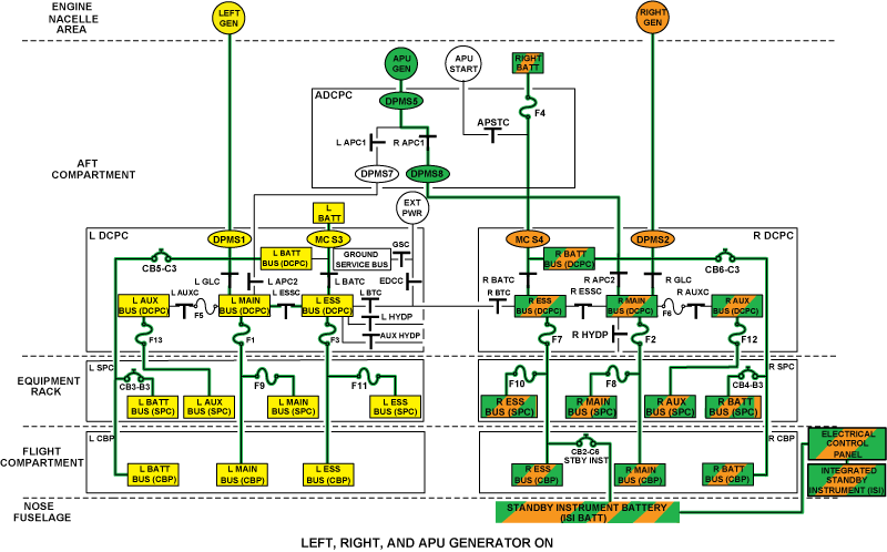
Each SPC receives electrical power from the applicable DCPC through:
- Three SPC input terminals (T4, T5, and T6) for the L/R MAIN BUS, L/R ESS BUS, and L/R AUX BUS power
- One SPC electrical connector (J2) for the L/R BATT BUS power.
The SPCs supply the secondary distribution to the aircraft loads in the forward section of the aircraft. They also mechanically connect the power available on the DCPC's distribution busses to the CCBPs.
The SPCs supply the secondary electrical distribution through different SPC terminals and SPC interface connectors.
The primary input/output terminals of the SPCs have the identification (ID) and the function descriptions given in the tables that follow:
Each SPC has five electrical connectors (J1, J2, J3, J4, and J5) used for different distribution, control, and monitoring functions.
For the control and monitoring functions in particular, a signal related to the voltage on the DCPC buses is sent by the SPC to the EICAS to control the bus outline indications (L/R ESS BUS, L/R MAIN BUS, and L/R AUX BUS outlines) that show on the ELECTRICAL synoptic page.


11/16/15
System Interface
The SPC system has interfaces with the applicable different electrical loads and also with the system and components that follow:
- DC Power Center (DCPC)
- Cockpit Circuit Breaker Panel (CCBP)
- Engine Indication and Crew Alerting System (EICAS).
10/15/20
Component Location Index
| Component Location Index | |||
|---|---|---|---|
| IDENT | DESCRIPTION | LOCATION | IPC REF |
| A37 | SECONDARY POWER CENTER (SPC) (LH) | ZONE(S) 221 | 24-62-01 |
| A38 | SECONDARY POWER CENTER (SPC) (RH) | ZONE(S) 222 | 24-62-01 |
| F9,F11 | SECONDARY POWER CENTER FUSES (LH) | ZONE(S) 221 | 24-62-03 |
| F8,F10 | SECONDARY POWER CENTER FUSES (RH) | ZONE(S) 222 | 24-62-03 |
| K2,K65,K98,K19,K21,K131,K133, K143 | SECONDARY POWER CENTER RELAYS (LH) | ZONE(S) 221 | 24-62-04 |
| K3,K66,K18,K20,K61,K130,K132 | SECONDARY POWER CENTER RELAYS (RH) | ZONE(S) 222 | 24-62-04 |
| - | REMOTE-CONTROL CIRCUIT BREAKER (RCCB) (LH) CONTACTOR K63 SENSOR K107 | ZONE(S) 221 | 24-62-05 |
| - | REMOTE-CONTROL CIRCUIT BREAKER (RCCB) (RH) CONTACTOR K64 SENSOR K106 | ZONE(S) 222 | 24-62-05 |