


Overview
The auxiliary direct current (DC) power center (Aux DCPC) system is an interface between the auxiliary power unit (APU) generator and the DC power centers (DCPC). It supplies control, protection, and distribution functions for the electrical power from the APU generator.
The Aux DCPC system also includes a power-supply control function for the APU starting system. The Aux DCPC system contains switching components, protection devices, and control logic circuits. With the functions of these components, the Aux DCPC system:
- Makes the necessary connections between the APU generator and the left and right DCPCs (LDCPC and RDCPC)
- Moves electrical power from the APU generator to the LDCP and RDCP
- Supplies battery power to the APU starting system
- Gives protection against short circuits and effects of unsatisfactory electrical-power quality
- Finds fault conditions of its components and transmits the data for display in the flight compartment and to the maintenance diagnostic computer (MDC).
Auxiliary DC Power Center (Aux DCPC)
The Aux DCPC is an electrical box that contains contactors, relays, and printed circuit boards (PCB). There is one Aux DCPC located in the aft equipment compartment of the aircraft. The Aux DCPC is supplied by an APU 28 VDC generator rated at 400 A.
The Aux DCPC contains the control, protection, and distribution components for the APU power generation and distribution system. These components include:
- An auxiliary generator control-unit (GCU)
- An auxiliary generator power-module (PMOD) which changes voltage of the ac permanent magnet alternator (PMA) into 25 VDC for use internally by the Aux DCPC
- Auxiliary power contractors (LAPC1 and RAPC1)
- Auxiliary-power start contactor (APSTC)
- APU logic control and protection electronics
- Differential protection monitoring sensors (DPMS) for the APU generator feeder (DPMS5, DPMS7, and DPMS8)
- Right-battery protection fuse (F4)
- APU start electronics
- BIT electronics
The Aux DCPC is made as follows:
- The Aux DCPC is made from aluminum sheet metal as a rigid box
- The Aux DCPC contains an epoxy baseplate which is along the full length and width of the box
- The contactors and current sensors are attached to the top surface of the baseplate
- The busbars are below the baseplate
- The electronic PCBs are installed in a metallic cage against an outer wall of the box, to give protection against the effects of electromagnetic interference (EMI) and heat
- All electronic connectors are installed on the busbar side of the box. Connections to the electronic PCBs are made through a motherboard.

Generator Control Unit (GCU)
The generator control unit (GCU) is a printed circuit board (PCB). It includes two separated circuits, one for generator voltage control and one for GCU protection function. There is one GCU for each main generator. All the GCUs are the same and they are fully interchangeable. This PCB is located in their related DC power center (DCPC).
The GCU has the following main functions:
- Regulate the corresponding generator voltage
- Control the generator line contactor
- Protect generator and distribution system from regulator or generator fault, and
- Monitor and test the generation channel and its own circuits (BITE).
Auxiliary Generator Power Module
As for the main generators, the auxiliary generator power module supply a dedicated internal power supply for the Aux DCPC. There is one auxiliary generator power module and it is located in the Aux DCPC.
The power module contains a rectifier circuit which takes ac voltage from the PMG of the generator and converts it into 25 V DC for use by the GCU, DCPC logic and protection electronic PCBs.


Auxiliary DC Power Center (Aux DCPC) Fuse
The type of fuse installed in the Aux DCPC is F4 (500 ampere (A)). The fuse gives protection for the distribution cables in the event of a circuit malfunction. The fuse isolate the circuits which keep the effect of a wiring malfunction to a minimum. This prevents power loss to the other power users, supplied from the same power source.
A fire could occur if the supply of power to a circuit which has a malfunction is not isolated. The fuse isolates the circuit which keeps the risk of a fire to a minimum. The Aux DCPC fuse is used for a high electrical power load (more than 50 A).
If a fuse isolates a circuit the fuse can not directly cause a dangerous condition of operation. Thus a safe flight and landing can be done.
There is no access to the Aux DCPC fuse in flight because it is located in the avionics racks.

Auxiliary DC Power Center (Aux DCPC) Relays
The type of relays that are installed in the Aux DCPC is 2PDT (10 A).
There are two relays in the Aux DCPC. They are as follows:
- K160 (2PDT): the APU generator relay inverts the APU generator OFF signal from the RSPC
- K96 (2PDT): the APU fuel valve relay connects the left essential-bus power supply to the APU fuel shut off valve.

Auxiliary Power Contactor
There are two auxiliary power contactors (LAPC1 and RAPC1) in the Aux DCPC.
The function of these two contactors is to connect the APU generator to the applicable left or right main bus.
Each connector operates in series with another connector in the applicable DCPC (LAPC2 for LDCPC and RAPC2 for RDCPC).
Note:
The four contactors LAPC1, LAPC2, RAPC1, and RAPC2 are controlled by the APU GCU and the auxiliary-power-center primary logic.

Auxiliary Power Start Contactor
There is only one auxiliary power start contactor (APSTC) in the Aux DCPC.
The function of the APSCTC contactor is to connect the APU starter motor to the right battery.

Auxiliary Power-Center Primary Logic
The auxiliary power center logic unit is a logic PCB installed in the Aux DCPC.
The auxiliary-power center primary logic supplies the control logic of the Aux DCPC contactors.
The logic PCB includes instructions for the functions that follow:
- Control of primary distribution contactors (LAPC1, LAPC2, RAPC1, and RAPC2)
- Power interface between the external signals and the APSTC contactor
- Internal built-in test (BIT) functions:
- Power-up built-in-test (PBIT)
- Continuous built-in-test (CBIT).
- Communication functions:
- Between logic PCB/protection PCB
- Between ELECTRICAL control panel/Aux DCPC.

Auxiliary Power Unit Sensor
There are three auxiliary-power-unit sensors in the Aux DCPC, which are differential protection monitoring-sensors (DPMS5, DPMS7 and DPMS8).
The DPMS sensors give protection to the auxiliary and main buses against APU generator overload.

System Operation
APU Starting System
The APSTC contactor in the Aux DCPC is used to connect electrical power to the APU starter motor (APU ST). The APU starter motor operates when the APSTC contactor is energized.
The right battery is the usual supply to the APU starter motor. However, if the right battery is not available, the left battery can be connected to supply the APU starter motor.
Note:
The operation of the APU starting system is the same when the aircraft is on ground or in flight.
R BATT APU-Start
The R BATT as the APU starting source is the usual configuration. The power from the R BATT is supplied to the APU starter through the APSTC contactor. In the R BATT APU-start configuration, the logic functions of the electrical system make sure that the right battery is disconnected from the bus distribution system during the APU start operation. This is done to prevent current surges and so that the voltage on the busses does not decrease.
L BATT APU-Start
The L BATT as the APU starting source is an unusual configuration that is used when there is a fail condition in the right battery. When there is an APU start command while the R BATT has a fail condition, the power from the L BATT is automatically supplied to the APU starter through the four contactors in the DCPCs (LBATC, LBTC, RBTC, and RBATC) and the APSTC contactor.
During an APU starting operation with the L BATT APU-start configuration, the voltage on the busses decreases because of the fact that the left battery is not disconnected from the bus system.
Possible APU-Start configurations include the examples that follow:
- APU start with R GEN and R BATT not available
- APU start with L BATT available only (emergency condition).
R GEN and R BATT not Available
When only the L GEN is on-line, the right battery is not available, and there is an APU start command, the power from the left busses is automatically supplied to the APU starter through the bus tie contactors (LBTC and RBTC), the RBATC contactor, and the APSTC contactor.
Note:
Because the L GEN is on-line, it supplies the busses and cross-starting occurs. This lets the L GEN help start the APU in parallel with the battery.
Emergency Condition
In emergency condition (L GEN, R GEN, and R BATT not available), an APU start command will cause the L BATT to supply automatically the APU starter. In this condition, power from the left battery will be supplied to the APU starter through the bus tie contactors (LBTC and RBTC), the RBATC contactor, and the APSTC contactor.


11/13/15
Control and Displays
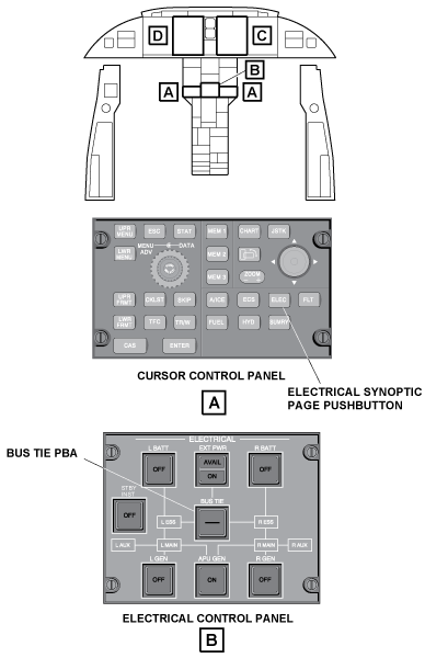
The APU generator is connected to the aircraft electrical buses when the APU GEN pushbutton annunciator (PBA), on the ELECTRICAL control panel, is pushed. By default, the APU generator connects to the R MAIN BUS, except when it replaces an inoperative engine generator. In this condition, the APU generator connects to the side that has the inoperative generator.
Electrical power from the APU generator is sent to the left or right main buses, as applicable, through the auxiliary power contactors LAPC1 or RAPC1. LAPC1 and RAPC1 contactors operate in series with LAPC2 contactor (in LDCPC) and RAPC2 contactor (in RDCPC) respectively.
The Aux DCPC logic functions use inputs from the auxiliary GCU and the DCPCs to close or open as applicable these contactors to connect/disconnect the APU generator to/from the main bus (L MAIN BUS or R MAIN BUS).
The Aux DCPC supplies the EICAS with monitoring signals related to the APU generator voltage and current. The Aux DCPC also sends, through the DCPCs, other APU generator status data to the EICAS. The APU generator monitoring-data is used by the EICAS to show APU generator indications on the ELECTRICAL synoptic page. The ELEC pushbutton on the cursor control panel, when pushed, shows the ELECTRICAL synoptic page on the lower half of the multi-function display (MFD).
The displays related to the APU generator operation on the ELECTRICAL synoptic page are:
- The APU voltage indication. This indication is white (no voltage), green (usual), or amber (value less than 24 V or more than 31.5 V)
- The APU current indication. This indication is white (no current), green (usual), or amber (value greater than 500 A)
- The APU generator outline which show in white (not in use), green (usual), amber (output less than 24.0 V or greater than 31.50 V)
- The APU power line which shows in white (not energized), or green (energized).
The monitoring data supplied through the Aux DCPC is also used by the EICAS to show applicable crew alerting system (CAS) messages related to the APU generator power.
APU generator related CAS messages show when one of the conditions that follow occurs:
- The APU generator voltage is not correct (APU GEN FAIL caution message, if the voltage is not between 24.0 V and 31.0 V)
- The APU generator has an overload condition (APU GEN OVERLOAD caution message, if the current is greater than 500 A and less than 700 A)
- The APU generator has been manually set off (APU GEN OFF status message).


11/13/15
System Interface
The Aux DCPC system has interfaces with the components/systems that follow:
- Primary DC Power System
- Battery System
- DC Power Center (DCPC) System
- Engine Indication and Crew Alerting System (EICAS)
- Starter Motor
- Electronic Control Unit (ECU)
- Permanent Magnet Alternator (PMA)
System Monitoring
The Aux DCPC uses its internal BIT functions (PBIT and CBIT) and the signals it receives from the APU generator (voltage and current inputs) to supply the EICAS with monitoring data related to the operation of the APU generator. The EICAS shows the applicable indications on the ELECTRICAL synoptic page and, when necessary, gives the applicable CAS messages.
System Test
The electrical system has built-in test (BIT) functions that supply status of the electrical system. They include the BIT function for the logic and protection circuits of the Aux DCPC. This BIT includes a power-up BIT (PBIT) and a continuous BIT (CBIT). The PBIT operates on ground only and for a maximum of 0.5 seconds. The PBIT test is inhibited in flight. The CBIT starts immediately after the PBIT has completed. The CBIT operates continuously as long as the system is energized. If the BIT tests find a fail condition, the Aux DCPC sends an applicable data to the EICAS and to the MDC.
10/15/20
Component Location Index
| Component Location Index | |||
|---|---|---|---|
| IDENT | DESCRIPTION | LOCATION | IPC REF |
| A196 | AUXILIARY DC POWER CENTER (AUX DCPC) | ZONE(S) 311/312 | 24-64-01 |
| F4 | AUXILIARY DC POWER CENTER FUSE | ZONE(S) 311/312 | 24-64-03 |
| K96/K160 | AUXILIARY DC POWER CENTER RELAYS | ZONE(S) 311/312 | 24-64-04 |
| K71/K72 | AUXILIARY DC POWER CONTACTOR | ZONE(S) 311/312 | 24-64-05 |
| K62 | AUXILIARY POWER START CONTACTOR | ZONE(S) 311/312 | 24-64-09 |
| PCB11 | AUXILIARY POWER CENTER PRIMARY-LOGIC | ZONE(S) 311/312 | 24-64-13 |
| DPMS5/DPMS7/DPMS8 | AUXILIARY POWER UNIT SENSOR | ZONE(S) 311/312 | 24-64-17 |