


Overview
The auxiliary power unit (APU) fire detection system is a dual-loop fire detection system. These loops are connected to the FIREX control unit (FIREX-CU). The APU has two fire detection loops (A and B). Each loop has two fire detection elements connected in series. Fire detection loops A and B share the same mechanical mount and are electrically isolated. The two ends of each loop are electrically connected to the FIREX-CU. This makes each loop single-fault tolerant against open circuits. Each detection loop is attached to the aircraft with clamps.
The APU fire detection system has an interface with the SYSTEMS TEST control panel.
01/04/16
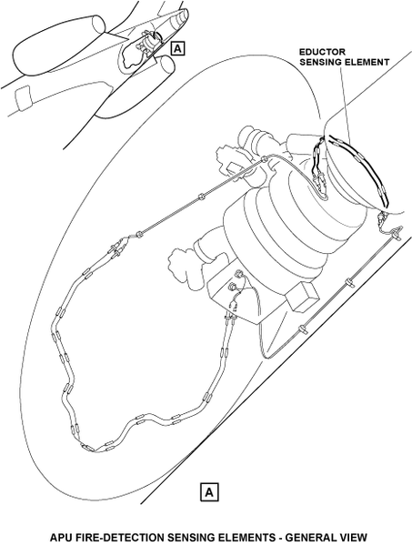
Eductor Sensing Element
The eductor sensing element is on the eductor of the APU. It senses the heat pushed aft of the eductor because of the APU airflow.
The alarm trip temperature (223 °C [433.4 °F]) is given when approximately 100 °C (212.0 °F) is added to the maximum temperature of operation (95 °C [203.0 °F]) to which the sensing elements are usually exposed. The 100 °C (212.0 °F) value decreases the risk of incorrect or irregular alarms from unusually high temperatures.
The alarm temperature value is in relation to the sensing element length, core material, and the properties of other elements in the loop. The alarm condition goes out when the temperature decreases to <203 °C (397.4 °F).
01/04/16
Firewall Sensing Element
The firewall sensing element is on the forward firewall of the tail-cone. It senses the heat from fires located near the tail-cone drain, APU fuel pump, and APU generator.
The alarm trip temperature (184 °C [363.2 °F]) is given when approximately 100 °C (212.0 °F) is added to the maximum temperature of operation (72 °C [161.6 °F]) to which the sensing elements are usually exposed. The 100 °C (212.0 °F) value decreases the risk of incorrect or irregular alarms from unusually high temperatures.
The alarm temperature value is in relation to the sensing element length, core material, and the properties of other elements in the loop. The alarm condition goes out when the temperature decreases to less than 168 °C (334.4 °F).

Operation
The FIREX-CU receives 28 VDC power from the L ESS BUS and R ESS BUS for detection and monitoring functions. The FIREX-CU discrete signals and ARINC 429 bus signals interface with the data concentrator unit (DCU) for ARINC bus control functions.
The FIREX-CU continuously monitors the resistance to ground of each loop. In fire conditions, the loop resistance decreases and supplies a loop fire indication at the FIREX-CU. The FIREX-CU includes short-circuit discriminator circuits to identify the difference between a loop fire and loop failures.
The FIREX-CU has two modes of operation, dual-loop and single-loop logic detection. In the dual-loop detection mode, the A and B loop signals are necessary to the FIREX-CU to cause a zone fire alarm. In the single-loop detection mode, only one fire signal from an element is necessary to cause a fire alarm. The control unit automatically changes to the single-loop detection mode in failure conditions (loss of a single channel or loop).
When zone fire conditions are met, the FIREX-CU transmits the applicable fire warning to the engine indicating and crew alerting system (EICAS) through the ARINC 429 and hardwired discretes. Faults on the detection loops are identified by the FIREX-CU with indications supplied to the EICAS through the data concentrator unit (DCU).
If there is a fire sensed, the following visual indications and alarm sounds occur:
- APU FIRE warning message shown on the EICAS
- On the WARNING/CAUTION panel, the WARNING light will come on
- APU FIRE arming push button annunciator on the engine control panel will come on
- A triple chime will be heard
The APU FIRE warning message will show when one of the fire detection loops on the APU has sensed a fire.
The APU FIRE DET FAIL caution message will show when the APU fire detection system has failed.
The EICAS messages that follow are related to the APU fire detection system:
| EICAS MESSAGE(S) | LEVEL (COLOR) |
|---|---|
| APU FIRE | WARNING (red) |
| APU FIRE DET FAIL | CAUTION (amber) |
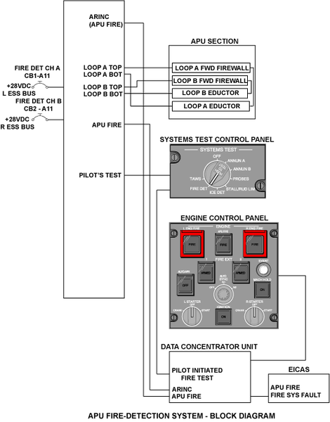
System Test
A test of the fire detection system can be done with the rotary test switch on the SYSTEMS TEST control-panel set to the FIRE DET position. When the test switch is momentarily pushed (approximately 1 second), it starts a test of the entire fire, overheat and smoke detection system.