


02/01/16
Overview
The rudder system gives the flight crew the necessary yaw control of the aircraft. The usual mode of operation is by mechanical inputs from the pilots' controls to two hydraulically-operated power control units (PCUs). One PCU is driven from the left hydraulic system and the other PCU is driven from the right hydraulic system.
There are two sets of rudder pedals with which the flight crew can continuously change the angular position of the rudder. The pilots transmit their inputs from the pedals through levers, bellcranks and cables to the two PCUs in the vertical stabilizer. The PCUs cause a movement of the rudder control surface which is directly in proportion to the pilot's rudder pedal input. An artificial feel unit puts a load on the rudder pedals to simulate aerodynamic loads.
The left hydraulic system supplies power to the upper rudder PCU and the right hydraulic system supplies power to the lower PCU. If the right hydraulic power is not available, the lower rudder PCU will automatically be energized by the auxiliary hydraulic power. This system supplies pressure to the rudder lower PCU to help the pilot move the rudder. If a series of defective components causes the available hydraulic pressure to decrease to zero, the rudder can be controlled by mechanical input only (manual reversion mode).
The rudder control system has an interface with SYSTEMS TEST Control-Panel.


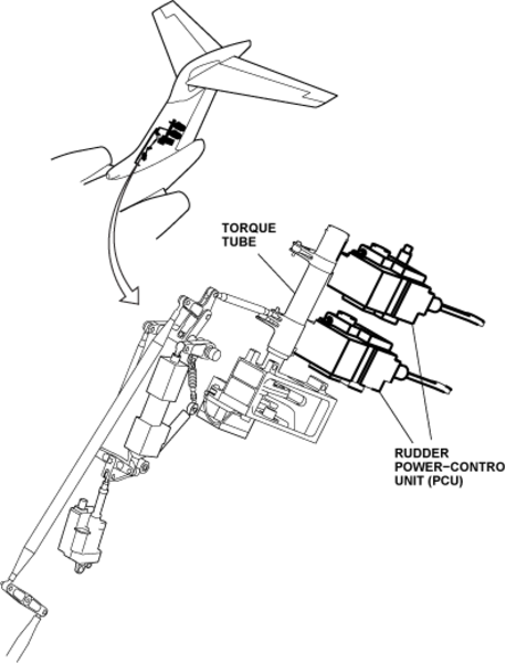
Rudder Power Control Unit (PCU)
There are two hydraulic rudder PCUs attached to the rear spar of the vertical stabilizer at FS889.84 and FS929.54, one above the other. A torque tube in the rudder control circuit is installed parallel to the rudder hinge line. The one control input to the torque tube gives two parallel outputs, each connected to a PCU input lever. The PCU output links attach to points on the left side of the rudder control surface leading edge.
The left hydraulic system energizes the upper rudder PCU and the right hydraulic system energizes the lower rudder PCU. If the right hydraulic system is not available, the lower rudder PCU is energized automatically by the auxiliary hydraulic system. Manual reversion occurs if no hydraulic pressure is available from these three systems.
The rudder PCUs give protection to the rudder control surface against gust loads while the aircraft is on the ground. This protection continues for up to eight hours after hydraulic pressure is released.
Rudder Position Sensor
The position sensor is a dual channel rotary variable differential transducer (RVDT). It is installed in the vertical stabilizer adjacent to the upper rudder PCU. It connects to the rudder control surface with two links which turn the internal mechanism of the sensor as the rudder moves. The sensor sends data about the position of the rudder control surface to the EICAS, the flight guidance computer and the flight data recorder. The indication of the rudder position is shown on the flight controls synoptic page of the EICAS.

Rudder Control Surface
The rudder control surface is the same length as the rear spar of the vertical stabilizer, to which it is attached. It has four hinge points to connect it to the vertical stabilizer and two positions to connect the PCUs. Movement of the pilot's or copilot's right rudder pedal fully forward causes a maximum rudder surface travel of 30 degrees to the right. The conditions for this maximum angle are that the aircraft is on the ground, or the airspeed is below 145 knots. Inputs to the PCUs are limited by primary stops on the PCU torque tube and secondary stops on the forward quadrant. The primary stops can be adjusted to give 1.5 degrees of overtravel. This will let the rudder move a total of 31.5 degrees, at which point the PCU becomes the primary stop.

Yaw Force Sensor
The two force sensors have the primary function of rigid rods which are installed between the rudder pedal T-levers and the forward quadrant input lever. One sensor connects to the pilot's rudder control and the other one to the copilot's control. The other function of the yaw force sensors is to supply data on the force at those points in the rudder control circuit to the flight data recorder.

Rudder Control Feel Unit
The rudder control feel unit is a centering spring which has a built-in compression load. Inputs from the rudder pedals, which cause the aft quadrant to turn, also move the feel unit. The rudder-control feel unit applies pressure back to the rudder pedals which gives the flight crew some simulated feel.

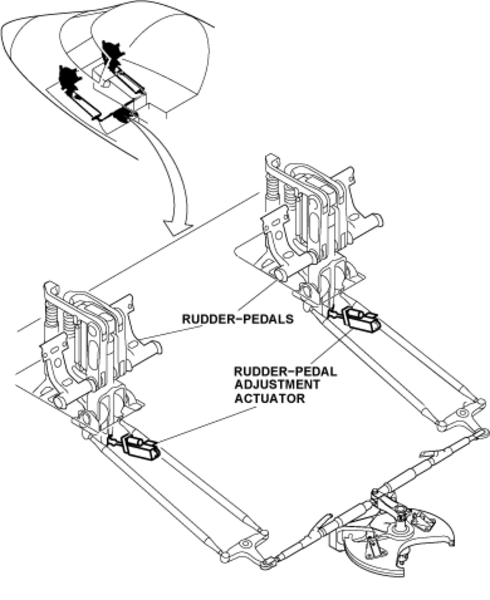
Rudder Pedal Adjustment Actuator
An electrical adjustment actuator is connected to the main support post of the pilot's and the copilot's rudder pedal mechanisms below the flight compartment floor. Each pilot can adjust the position of the rudder pedals forward or aft as necessary for their height. The actuators can move the pedals approximately 3.17 in (8.05 cm) aft and 4.06 in (10.31 cm) forward of their neutral positions. The adjustment switches are on the pilot's and copilot's side panels.
Rudder Travel Limiter Actuator
The rudder travel limiter actuator puts a limit on the movement of the rudder control surface, as a function of airspeed. This makes sure that the aerodynamic force on the rudder is not more than the structural limit permitted by the vertical stabilizer. The horizontal stabilizer trim electronic control unit (HST ECU) controls the movement of the rudder travel limiter actuator.
The rudder travel limiter actuator has a cam, a limiter arm, two springs, a transducer and a mounting frame. The cam is part of the rudder PCU input torque tube. The actuator puts the limiter arm in a position where it stops movement of the cam. Thus the movement of the rudder control surface is also stopped. The two springs make sure that the limiter arm lets the rudder move fully left and right if the travel limiter becomes accidentally disconnected from the torque tube during flight.

Rudder Centering-Spring Cartridge
A rudder centering-spring cartridge is installed on the yaw damper lever-assembly directly above the rudder trim actuator. The function of the rudder centering-spring cartridge is to adjust for the large mass of the yaw damper assembly. If the yaw damper assembly and the rudder trim actuator become mechanically disconnected, the centering spring cartridge will move the assembly to the neutral position. This will prevent the large mass of the yaw damper assembly to move an input to the rudder control surface.

02/01/16
System Operation
The rudder pedals connect to pushrods, levers, shafts, and the rudder pedal transducer. This is a permanent connection which has no procedure to disconnect the pilot's and the copilot's rudder controls from each other (as in the aileron and elevator controls).
When the pilot applies a force on the bottom of the rudder pedal, it causes the L-shaped lever to turn. Control rods and a T-lever transmit the movement from the L-shaped lever to the forward quadrant. The linkage mechanism causes the same input to the forward quadrant for equivalent inputs from the pilot or copilot. A forward movement of the left or right pedal causes the other pedal to move to the aft. The forward quadrant has an input lever and two secondary stops found on the top side and a rudder pedal transducer on its bottom side.
Note:
When on the ground, if the pilot applies a force on the top of the rudder pedals, hydraulic pressure will be applied to the brake control system.
Two cable circuits start at the forward quadrant and go to the rear fuselage together. When they get to the engine rotor-burst area the two cable circuits go in different directions. If there is a rotor burst, where one of the cable circuits is damaged, the other one can continue to operate the rudder.
The rudder-control feel unit connects to the aft quadrant and transmits a simulated feel force to the flight crew. A trim actuator in the circuit lets the flight crew move the neutral position of the rudder. A yaw damper connects in series with the trim actuator to supply an input to the PCU torque tube.
The left hydraulic system supplies power to the upper rudder PCU and the right hydraulic system supplies power to the lower PCU. If the right hydraulic power is not available, the lower rudder PCU will automatically be energized by the auxiliary hydraulic power. If the power from the three hydraulic systems is not available then the rudder control surface can be moved manually.
The rudder position indication is shown on the FLIGHT CONTROLS synoptic display on the EICAS status page. This display shows the rudder movements in the left or right positions on a scale with a rudder out-line pointer. There are marks at the full left, mid left, neutral, mid right and full right positions.
The RUDDER LIMITER FAIL caution message will show when the rudder limiter has failed. The RUDDER LIMITER FAULT advisory message will show when a minor failure that causes the loss of redundancy has occurred in the rudder limiter system. The RUD LIMITER IN TEST status message will show when the rudder travel limiter system does the manually started system test.
The EICAS messages that follow are related to the rudder control system:
| EICAS MESSAGE(S) | LEVEL (COLOR) |
|---|---|
| RUDDER LIMITER FAIL | CAUTION (amber) |
| RUDDER LIMITER FAULT | ADVISORY (cyan) |
| RUD LIMITER IN TEST | STATUS (white) |


03/30/22
System Test
A test of the rudder limiter system can be done with the rotary test switch on the SYSTEMS TEST control-panel set to the STALL/RUD LIM position. When the test switch is momentarily pushed (approximately 1 second), it starts a test of the entire rudder limiter system. If this pre-flight test is not done for 10 flights the RUDDER LIMITER FAULT advisory message will be shown.

10/15/20
Component Location Index
| Component Location Index | |||
|---|---|---|---|
| IDENT | DESCRIPTION | LOCATION | IPC REF |
| - | RUDDER POWER-CONTROL UNIT (PCU) | ZONE(S) 341 | 27-21-05 |
| MPE21 | RUDDER POSITION SENSOR | ZONE(S) 341 | 27-21-09 |
| - | RUDDER CONTROL SURFACE | ZONE(S) 342 | 27-21-13 |
| MT113 | YAW FORCE SENSOR (LH) | ZONE(S) 141 | 27-21-17 |
| MT114 | YAW FORCE SENSOR (RH) | ZONE(S) 142 | 27-21-17 |
| - | RUDDER-CONTROL FEEL UNIT | ZONE(S) 330 | 27-21-21 |
| MPE17 | RUDDER-PEDAL ADJUSTMENT ACTUATOR (LH) | ZONE(S) 141 | 27-21-25 |
| MPE18 | RUDDER-PEDAL ADJUSTMENT ACTUATOR (RH) | ZONE(S) 142 | 27-21-25 |
| MPE79 | RUDDER TRAVEL LIMITER ACTUATOR | ZONE(S) 341 | 27-21-28 |