


Overview
The Rudder Trim System is in the rudder control system. The rudder control system is a standard, non-reversible hydro-mechanical system that has:
- Pilot and Copilot Control Pedals
- Levers
- Cranks
- Sectors
- Cables
- Pulleys
The cables and pulleys connect to the rudder hydraulic actuators.
Rudder Trim Actuator
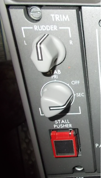
The rudder trim actuator (RTA) supplies manual rudder trim control. The manual trim control system lets the pilot and copilot remove out of trim forces. The RTA is an electro-mechanical linear type that attaches between the trim lever assembly and the primary structure in the vertical stabilizer. The actuator supplies rudder surface movement through a linkage connected to the yaw damper linear actuator and the yaw damper provision rod. The RTA is controlled manually through a rotary switch found on the center pedestal.
The RTA is linear in operation and energized by a magnetic direct current motor. The output shaft transmits turn movement.
The turn movement changes linear through a screw nut device and a turn limiter device. The rudder trim actuator is found adjacent to the rudder aft quadrant. They are in an area of the aircraft where the air temperature and pressure are not controlled.

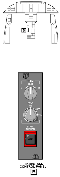
TRIM/STALL Control Panel
The TRIM/STALL control panel is found on the center pedestal. There is a pushbutton annunciator (PBA) with the legend STALL PUSHER for the stall protection system. The stall pusher PBA is usually on and must be pushed to off. When the STALL PUSHER PBA is pushed, the light comes on and shows the legend OFF.
02/01/16
System Operation
The RTA is a self-contained dc motor that operates on 28 VDC. It is controlled by the TRIM RUD L R switch installed on the TRIM/STALL control panel on the center pedestal. With the switch set to the L position, the RTA extends and causes the rudder control surface to move to the left to a maximum of 13.00 degrees. With the switch set to the R position, the RTA retracts and causes the rudder control surface to move to the right to a maximum of 13.00 degrees.
The activation of the RTA supplies an input to the trim lever. The trim lever then moves the yaw damper linear-actuator and the yaw damper provision rod. The rod and the actuator are connected in series and operate parallel to each other. When the rod and actuator move, they cause the mixer mechanism, main lever bell crank and push rod to move the torque tube. The torque tube will then move the PCUs to the set the rudder trim.
The rudder can be out of balance if there was a mechanical separation of the RTA at the trim lever. This is because of the mass of the yaw damper assembly. A centering spring cartridge is attached to the trim lever to prevent the effect of an out of balance input to the rudder surface.
The rudder trim indication is shown on the primary page of the engine indication and crew alerting system (EICAS) display. The indication is in the upper, center area of the display. This display shows the rudder movements to the left or right positions on a scale with a pointer. The scale has a legend RUD and marks at the full left (L), the full right (R), the mid L and R, and the neutral positions.
The color of the pointer will show red when the rudder trim is out of the take-off set range and the CONFIG RUDDER TRIM warning message shows. The pointer will show green when the rudder is in the EICAS take-off set range. When the pointer is not red or green it will show white for usual operation.
The CONFIG RUDDER TRIM warning message will show when the aircraft is on the ground for 30 seconds and the rudder trim is not correctly configured for take-off.
The EICAS message that follows is related to the rudder trim system:
|
EICAS MESSAGE(S) |
LEVEL (COLOR) |
|---|---|
| CONFIG RUDDER TRIM |
WARNING (red) |


10/15/20
Component Location Index
| Component Location Index | |||
|---|---|---|---|
| IDENT | DESCRIPTION | LOCATION | IPC REF |
| MPE22 | RUDDER TRIM ACTUATOR | ZONE(S) 341 | 27-22-01 |