


Overview
The stall protection system (SPS) supplies protection to the aircraft to prevent high levels of angle-of-attack. A high level angle-of-attack can cause the aircraft to go into a stall condition.
02/03/16
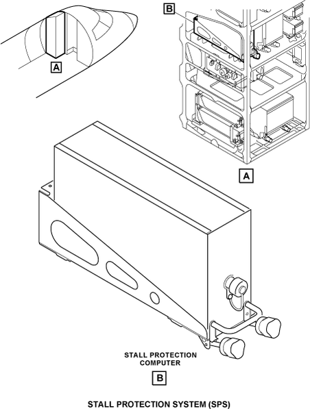
Stall Protection Computer
The stall protection computer (SPC) is a digital dual-channel computer, found in one chassis. It is installed in the LH equipment rack. The two channels operate the same.
The SPC uses signals from the angle-of-attack (AOA) sensors and other aircraft systems to supply data to the components and the systems that follow:
- Stick Shakers
- Stick Pusher
- Electronic Flight Instrument System (EFIS)
- Engine Indication and Crew Alerting System (EICAS)
The L ESS BUS supplies 28 VDC to the SPC channel A. The R MAIN BUS supplies 28 VDC to the SPC channel B.
The SPC has built-in-test (BIT) and diagnostic functions. The three modes of BIT are power-up, continuous, and pilot activated test (PAT). The SPC keeps fault data in memory. Access to the data is through the front connector when in the maintenance mode.
02/03/16
Stall Protection Computer Tray
The stall protection computer tray is installed in the LH equipment rack. It has four fasteners which hold the stall protection computer in the tray. The tray has a connector for the stall protection computer to connect to the aircraft.

Stick Shaker
There are two stick shakers installed on the forward side of each control column. Each stick shaker has a dc electrical motor which moves an eccentric weight. The stick shakers shake the control column to tell the pilot and copilot of a near stall condition. The force of the stick shaker against the control column is 10 lbs (4.54 kg).
The stick shaker turns on with outputs from the SPC. A command function from the SPC channel A controls the pilot shaker and a command function from the SPC channel B controls the copilot shaker. The 28 VDC power for the left stick shaker is supplied from L ESS BUS, STALL L SHKR circuit breaker, through the SPC. The 28 VDC power for the right stick shaker is supplied from R MAIN BUS, STALL R SHKR circuit breaker, through the SPC.

Angle-of-Attack Sensor
Two angle-of-attack (AOA) sensors are installed at FS308.89 and at WL96.56 on the forward fuselage of the aircraft, on the left and right sides. The AOA is a swept vane type, dual resolver sensor. The sensor vane turns to align with the air flow along the fuselage. This is to measure the direction of the airflow in relation to the fuselage (local flow). The turn movements are changed to an analog signal to supply a continuous electrical output. This electrical output represents the angle of attack.
A damper is used to keep the movement of the AOA vane to a minimum when the aircraft is in irregular air conditions. The SPC supplies reference voltage to the AOA vanes. The AOA vanes have internal heaters to supply the sensors with anti-ice functions.
The L ESS BUS supplies 28 VDC to the left AOA vane heater. The L MAIN BUS supplies 28 VDC to the left AOA case heater. The R MAIN BUS supplies 28 VDC to the right AOA vane heater and the right AOA case heater.


Stick Pusher Actuator
The stick pusher actuator is an electromechanical device that has a rotary output. The stick pusher actuator is found below the floor of the forward fuselage on the left side. The SPC supplies two signals to the stick pusher actuator that cause the output pinion to move counterclockwise. The L MAIN BUS supplies 28 VDC power to the stick pusher actuator.

Stick Pusher Capstan
The stick pusher capstan is a mechanical device that accepts a rotary input from the output pinion of the stick pusher actuator. It is found below the floor in the forward fuselage on the left side. The capstan moves the aircraft control cables through a cable pulley. The capstan also has a slip clutch to override the actuator. This lets the cable pulley turn if the actuator output is defective, the actuator gear is locked, or the ball bearings are defective. The force against the control column from the stick pusher actuator through the stick pusher capstan is 80 lbs (36.29 kg).

TRIM/STALL Control Panel
The TRIM/STALL control panel is found on the center pedestal. There is a push button annunciator (PBA) with the legend STALL PUSHER for the stall protection system. The stall pusher PBA is usually on and must be pushed to off. When the STALL PUSHER PBA is pushed, the light comes on and shows the legend OFF.

System Operation
The System Operation description includes:
Theory of Operation
The stall protection system uses angle-of-attack (AOA) and mach number as the primary parameters to supply warnings and protection from a stall condition. The system supplies continuous ignition to the engines to make sure the engines continue to operate during high angles of attack.
When the AOA increases to the angle at which automatic ignition occurs, the SPC tells the power plant ignition-system to start the igniters.
If the angle of attack increases, the system supplies a visual and sound indication as a stall warning. The SPC sends a 28 VDC signal to the stick shakers. This operates the stick shakers to give a stall warning as a mechanical vibration of the control columns. A STALL aural warning will be heard while the stick shaker operates. The STALL aural warning has the highest priority and cancels all other voice alarms. If the autopilot is engaged, it is disengaged at the same time the stick shaker is operated. The SPC sends a signal to the flight guidance panel when the stick shaker disengages the autopilot.
If the angle of attack increases again, the stick pusher actuator pushes the control columns forward. This is to decrease the angle of attack and keep the aircraft out of a stall condition. The SPC sends two signals, one from each channel, to start the stick pusher actuator. Channel A supplies a signal for the motor of the stick pusher actuator. Channel B supplies a signal to engage the clutch for the stick pusher actuator.
The Master Disconnect Switch (MSW) on the control wheels sends signals to the stick pusher and SPC to prevent the operation of the stick pusher actuator.
Note:
This function is disabled for JAA registered aircraft by SB 350-27-001.
The STALL PUSHER PBA on the control panel prevents the operation of the stick pusher actuator when set to OFF.
Modes of Operation
The stall protection system operates in the primary mode, which is the usual mode, or the SPS Advanced Mode (SAM). The primary mode uses preset values of when to start the stick shaker, stick pusher actuator, and automatic ignition.
The system operates in SPS advanced mode when the pilot starts wing anti-ice, or one of the ice detectors senses ice. In this mode, the values to start the stick shaker are less than the values for the primary mode. The values to start the automatic ignition and the stick pusher actuator do not change when in the SPS advanced mode. The system cannot go back to the primary mode if the conditions that set the SAM mode continue to operate.


03/30/22
Controls and Displays
On the Primary Flight Display (PFD), a Low Speed Awareness (LSA) thermometer can be shown. It shows in red and black at the lower right part of the airspeed tape and it gives a visual indication of the stall margin. The LSA moves up and gets to the airspeed pointer at the activation point of the stick shaker. While the stick shaker operates, a STALL red flag shows at the left of the attitude ball display.
The STALL PROTECT FAIL caution message will show when:
- The SPC has failed in one of the two channels (A or B)
- The stick pusher actuator has failed
- An AOA sensor has a failed
- There is a miscompare detect of more than a 3 to 5 degrees split between the essential AOA sensor inputs
- The essential AOA sensor inputs are not available
The STALL PUSHER OFF caution message will show when the MSW on one or the other control wheel has been pushed for longer than 10 seconds.
The L STALL SHAKER FAIL advisory message will show when the left shaker has failed.
The R STALL SHAKER FAIL advisory message will show when the right shaker has failed.
The STALL PROTECT FAULT advisory message will show when the SPC has sensed a fault and has reverted to a default flap settings of 30 degrees.
The STALL WARN BASIC advisory message will show when the SPC has incorrectly reverted to primary mode.
The STALL PUSHER OFF status message will show when the MSW on one or the other control wheel has been pushed for less than 10 seconds or the pusher has been inhibited by the STALL PUSHER PBA.
The SPC supplies the messages that follow to the EICAS:
|
EICAS MESSAGE(S)
|
LEVEL (COLOR)
|
|---|---|
|
STALL PROTECT FAIL
|
CAUTION (amber)
|
|
STALL PUSHER OFF
|
CAUTION (amber)
|
|
L STALL SHAKER FAIL
|
ADVISORY (cyan)
|
|
R STALL SHAKER FAIL
|
ADVISORY (cyan)
|
|
STALL PROTECT FAULT
|
ADVISORY (cyan)
|
|
STALL WARN BASIC
|
ADVISORY (cyan)
|
|
STALL PUSHER OFF
|
STATUS (white)
|
The SPS uses the components and systems that follow for stall indication and control:
- Central Display System - A sound warning is supplied through the Radio Interface Unit (RIU) when the stick shaker starts. The PFDs show visual indications of rate of speed to a stall. The Crew Alerting System (CAS) shows messages of fault conditions of the SPS.
- Aircraft switches - The MSW on the control wheels and the STALL PUSHER PBA on the center pedestal can disable the stick pusher.
- Air-Data-Sensor Heater-Current Monitor - Monitors the heaters in the AOA vanes for anti-icing.

System Test
The stall protection system has three modes of built-in-test (BIT) that includes:
Power Up
The Stall Protection Computer does a test of the hardware for the system when it is turned on.
Continuous
The SPC continuously monitors the inputs and outputs from the components that have an interface with the stall protection system.
The SPC uses the fault data to set bits that show which LRU is defective. The SPC keeps the fault data in non-volatile memory. Access to that memory can be done during maintenance mode.
Pilot Activated Test (PAT)
The PAT is started through the SYSTEMS TEST control-panel on the center pedestal with the switch in the STALL/RUD LIM position. The PAT does a test of the stick shaker actuator, stick pusher actuator, autopilot disconnect, and sends ARINC data to simulate a stall. The PAT is inhibited when the aircraft is in air.
The PAT does the rudder travel limiter test with a RTL test bit sent by ARINC (approximately 12.5 seconds). Then it does the shaker/pusher test in which each SPC channel gives commands for auto-ignition, stick shaker, stick pusher, autopilot disconnect, and aural and visual warnings (approximately 4 seconds). After, the PAT does the stall simulation test in which the AOA sensor moves up with a rate of 8 degrees/second. Equivalent to the shaker/pusher test, commands are given for auto-ignition, stick shaker, stick pusher, autopilot disconnect, and aural and visual warnings at the different AOA angle value. Then, the AOA sensor moves down with a rate of 25 degrees/second and the two SPC channels stop to give commands. At the end, there is an internal BIT (approximately 1 seconds). The time to do the pilot activated test is 20 seconds.


02/03/16
System Interface
The stall protection system has interfaces with the components/systems that follow:
- Integrated Air System (IAS) Controller
- Flight Guidance Panel (FGP)
- Horizontal Stabilizer Trim Electronic Control Unit (HST ECU)
- Flap Control Unit (FCU)
- Spoiler Electronic Control Unit (SECU)
- Air Data Sensor Heater Current Monitor
- Ice Detector
- Data Concentrator Unit (DCU)
- Input/Output Concentrator Unit (IOC)
- Configuration Strapping Unit (CSU)
- SYSTEMS TEST Control Panel
- Central Display System
- Proximity Sensor Electronic Unit (PSEU)
- Integrated Standby Instrument (ISI)
- Air Data Computer
- Attitude Heading Computer (AHC)
- Maintenance Diagnostic Computer (MDC)
10/27/20
Component Location Index
| Component Location Index | |||
|---|---|---|---|
| IDENT | DESCRIPTION | LOCATION | IPC REF |
| A178 | STALL PROTECTION COMPUTER | ZONE(S) 221 | 27−32−01 |
| - | STALL-PROTECTION-COMPUTER TRAY | ZONE(S) 221 | 27−32−02 |
| A179 | STICK SHAKER (LH) | ZONE(S) 211 | 27−32−05 |
| A180 | STICK SHAKER (RH) | ZONE(S) 212 | 27−32−05 |
| A141 | ANGLE-OF-ATTACK SENSOR (LH) | ZONE(S) 121 | 27−32−09 |
| A142 | ANGLE-OF-ATTACK SENSOR (RH) | ZONE(S) 121 | 27−32−09 |
| A181 | STICK PUSHER ACTUATOR | ZONE(S) 141 | 27−32−13 |
| - | STICK PUSHER CAPSTAN | ZONE(S) 141 | 27−32−17 |
| PL26 | TRIM/STALL CONTROL PANEL | ZONE(S) 211 | 27−32−21 |