


02/05/16
Overview
The horizontal stabilizer (HS) supplies pitch trim to the aircraft. This section gives the description for the HS control system.
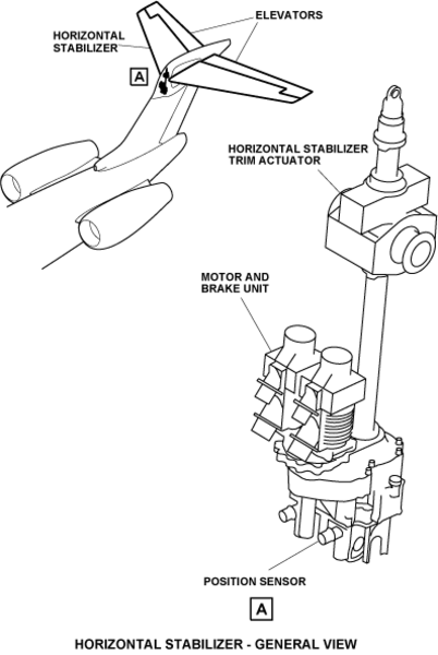
The pitch control is done by the trimable HS surface pivoting on the vertical stabilizer and two elevator surfaces which are hinged at the rear end of the HS. The pitch trim system includes malfunction detection with an automatic fail-safe shutdown and warning signal through the engine indication and crew alerting system (EICAS).
The pitch trim system is a electrical system with a movable horizontal stabilizer. An electromechanical trim actuator will set the HS. The electromechanical trim actuator is an adjustable length link between the HS and the vertical stabilizer. The range of movement of the horizontal stabilizer is between +2 degrees (the trailing edge up) and -12 degrees (the trailing edge down). Pilot/Copilot controls include pitch/roll trim switches and a trim/stall control panel.
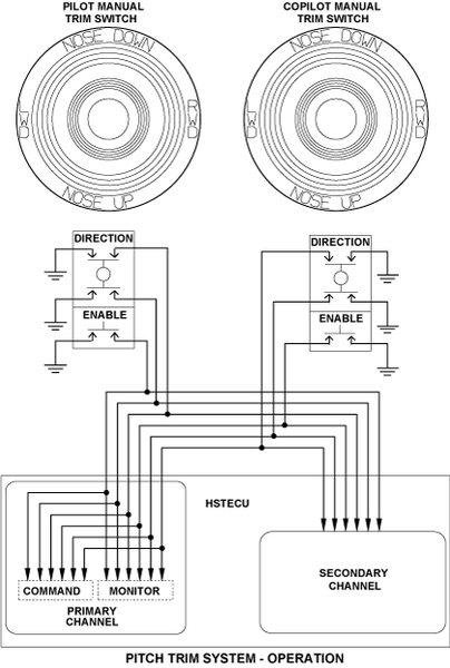
Pitch/Roll Trim Switch
The pitch/roll trim switches are found on the pilot's and copilot's handwheels. The pilot's switch has priority over the copilot's switch. The pitch/roll trim switch controls two engage-relays. These relays give power to one of two MCU channels (1 or 2). The primary engage-relay is found on the left direct current power center (DCPC). It tells the flight guidance computer (FGC) that the primary channel is engaged and thus autopilot and Mach trim functions are correct. The secondary engage-relay is found on the right DCPC.

Trim/Stall Control Panel
The TRIM/STALL control panel is found on the center pedestal. There is a pushbutton annunciator (PBA) with the legend STALL PUSHER for the stall protection system. The stall pusher PBA is usually on and must be pushed to off. When the STALL PUSHER PBA is pushed, the light comes on and shows the legend OFF.

Horizontal Stabilizer Trim Actuator (HSTA)
The HSTA is one mechanical actuator with two motors and two independently controlled channels. The unit is installed on the top of the vertical stabilizer. The actuator contains a bi-directional no-back. The no-back prevents actuator movement with a load that is two times the maximum aid load.
Horizontal stabilizer trimming is accomplished by changing the length of the HSTA. The HSTA lower end attaches to the fixed vertical stabilizer, while the translating nut of the HSTA attaches to the HS. Movement of the translating nut occurs when the ballscrew is rotated. The ballscrew is rotated by either of the two DC motors operating through a torque-summed gearbox.
Integral to the HSTA are two independently operated linear variable displacement transducers (LVDTs). These LVDT sensors are used for the following:
- HSTA position feedback
- EICAS HS trim indication
- Take-off configuration warning system
- Outputs to the flight data recorder (FDR)


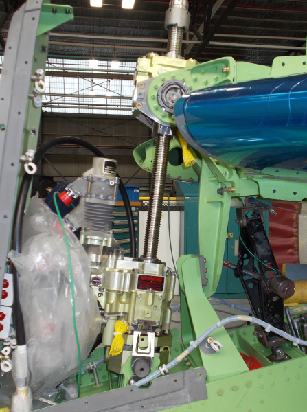
Motor and Brake Unit
The motor and brake unit contain solenoid operated brakes that are applied when the motor is not in operation. The HSTA operates by one of two brushless DC motors. One motor for the pitch-trim primary channel and one for the pitch-trim secondary channel. The motors interface with a torque monitored configuration through the same gearbox.

Motor Control Unit (MCU)
The MCU is found in the vertical stabilizer. It is a part of the aircraft pitch-trim system, which uses primary and secondary actuator systems. The MCU receives signals from the HST ECU. The MCU supplies the power drive signals to the brushless DC motors in the actuator to turn at the necessary speed and direction. The MCU supplies the necessary signals to be sent to the HST ECU.
The MCU has control and power supplies for the primary and secondary motors, which are in the HTSA assembly. For the primary channel motor, the command path supplies all control functions for the motor and brake releasing sequencing. Both the primary and secondary motor brake must be released before the motor can drive the actuator. The monitor path supplies all enabling and monitoring functions. The brakes are sequenced to be released before motor operation, and applied again after the motor has come to a stop following a HS trim event.
Each motor has an internal brake which is usually spring-loaded to the brake engaged condition. Each brake has two solenoid coils, each of which can disengage the brake.
The HST ECU supplies the solenoid power. The MCU is segregated into physically isolated sections, one section controls the primary motor and the other section controls the secondary motor.


Position Sensor
Position sensors have one channel. The channel has a primary winding and a center-tapped secondary winding. The sliding probe is on a stem. The sensor is a hermetic seal type with a necessary connector. Position sensors give the HSTA linear-output position on the aircraft.
The HSTA has two independently operated position sensors. The two sensors are energized and demodulated independently from each HST ECU channel. The sensor excitation and demodulation (in analog format) are available when either channel is in control.
The HSTA position is supplied to the data concentrator unit (DCU) from the primary channel through ARINC 429 data buses. The HSTA position is given to the DCU from the secondary channel in an analog format when the pitch-trim secondary channel is set. The DCU sends the HSTA position to the FDR.

Horizontal Stabilizer Trim Electronic Control Unit (HST ECU)
The HST ECU is a two-channel, primary/secondary system. The unit is packaged in a four MCU ARINC enclosure. The primary channel has:
- A command and monitor path with sensor data validations
- Cross-path data comparison and validations
- BIT and diagnostics
The HST ECU receives its electrical power from the aircraft 28 VDC system. The primary channel is powered from the left main bus while the secondary channel is powered from the right essential bus. Pilot action is necessary to switch control from the primary channel to the secondary channel.
The HST ECU secondary channel supplies fixed-rate manual trim only. The primary channel command and monitor paths are isolated from each other and the secondary channel.
Within the primary channel, a command path does all control functions. The command path has a sufficient capacity to monitor and to do all in-line and cross-path monitor functions. To send/receive data between command and monitor paths, there are two one way high speed serial interfaces. Any differences in command and monitor paths are detected. If the command and monitor paths do not agree, the system is set to the fail-safe mode (not operational) and an EICAS red warning CONFIG STAB TRIM message is displayed.
A monitor path independently processes all sensor data, models the command path for HS commands and does all enabling functions required for control of the HS. The monitor path can independently disable the HS controlled by the command path. Both paths are required to be fully operational and operating together before any pitch trim commands are executed.
The two channels give the correct sequence to the motors and brakes. Each channel of the HST ECU controls the operation of its respective motor. However, each HST ECU channel has direct control over the brake of either motor. The HST ECU is installed in the pressurized cabin. Air flow and the heat sink effect of the structure causes the HST ECU to be cool.
The HST ECU also supplies system status messages to the EICAS and autopilot interface.


Horizontal Stabilizer Trim Electronic Control Unit (HST ECU) Tray
The HST ECU tray is found in the LH equipment rack. Two hold down clamps on the tray engage the hold-down hooks on the HST ECU and attach the HST ECU to the tray. A connector at the rear of the tray gives interface from the HST ECU to the aircraft system wiring. The HST ECU front panel has two fold-out handles to help remove the transceiver from the tray.

Horizontal Stabilizer Surface
The horizontal stabilizer surface is a one-piece unit attached at the top of the vertical stabilizer. The horizontal stabilizer assembly includes spars and ribs. Rigid skin panels attach to the spars and ribs. It includes the pivot and actuation-mechanism mounting fittings for incidence adjustments and hinges for the elevators. It seals the interface with the vertical stabilizer.

02/05/16
System Operation
The pitch trim system operates in the automatic or manual mode. The automatic mode is supplied by the autopilot system. The autopilot system supplies automatic command signals to only the primary channel of the HST ECU. The primary channel trim rate is 0.4 degrees per second at airspeeds up to Mach 0.4. The trim rate decreases linearly to 0.1 degrees per second at Mach 0.8 and stays at 0.1 degrees per second above Mach 0.8. If Mach data is not available the trim rate defaults to 0.2 degrees per second.
The HST ECU releases the brake from the HSTA motors and simultaneously supplies a signal to operate the primary motor through the MCU. The motor drives the HSTA gearbox and the translating nut physically moves the HS to the commanded position. The position sensor gives a signal back to the primary channel to indicate the HS position. When the command position is reached the position sensor signal cancels the command signal and the HST ECU applies the brake to the motor again.
The HST ECU will also supply Mach-trim-compensation command signals independently of the autopilot to move the HS. The HST ECU primary channel computes Mach-trim-compansation. At high Mach numbers, the HST ECU computes commands to the HSTA which compensate for aircraft pitch-down tendencies when Mach increases. The autopilot-trim control signals however, have priority over the HST ECU Mach-trim-compensation signals. While the autopilot is engaged, the Mach-trim-compensation function is inhibited.
The manual mode is supplied through the pitch/roll trim switches found on the pilot's/copilot's handwheels. When operated these switches send a trim command signal to the HST ECU primary or secondary channel. The channel is determined by the position of the STAB trim switch on the trim/stall control panel. The primary channel trim rate is a function of airspeed (Mach). The secondary channel trim rate is a constant 0.2 degrees per second.
The HST ECU releases the brake on the applicable primary or secondary HSTA motor. It simultaneously supplies a signal to operate the applicable primary or secondary motor through the MCU. The motor drives the HSTA gearbox and the translating nut physically moves the HS to the commanded position. The position sensor gives a signal back to the primary channel to show the HS position. When the command position is reached the position sensor signal cancels the command signal and the HST ECU applies the brake to the motor again.
The manual pitch/roll trim switch has priority over the automatic mode (autopilot or Mach trim).
An additional function incorporated within the HST ECU is the rudder travel limiter (RTL). The RTL limits the rudder authority as a function of airspeed (Mach) to prevent deflection of the rudder surface beyond the structural limits of the vertical stabilizer. The rudder travel-limiter actuator (RTLA) is part of the RTL mechanism. The RTL mechanism provides different stops for the rudder control system. The RTLA determines the position of the stops. The HST ECU controls and monitors the RTLA and the RTL mechanism.
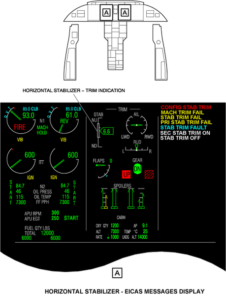
The horizontal-stabilizer trim indication is shown on the primary page of the EICAS display. The indication is in the upper, center area of the display. The display consists of an analog gauge with an overlaid band and a digital readout. This display shows the horizontal stabilizer movements to the up or down positions on a scale with a digital units readout pointer. The scale has a legend STAB and marks at the full nose up (NU), the full nose down (ND), and two mid positions. These positions indicate 0 units at the ND, 5 units, 10 units and 15 units at the NU position. At 0 units of stabilizer trim the stabilizer surface angle is +2.0 degrees. At 15 units of stabilizer trim the stabilizer surface angle is -13 degrees. The band overlaying the analog scale indicates the stabilizer takeoff set range. The stabilizer trim takeoff range is 5 to 12 units.
The EICAS messages that follow are related to the pitch trim system:
| EICAS MESSAGE(S) | LEVEL (COLOR) |
|---|---|
| CONFIG STAB TRIM | WARNING (red) |
| PRI STAB TRIM FAIL | CAUTION (amber) |
| SEC STAB TRIM FAIL | CAUTION (amber) |
| MACH TRIM FAIL | CAUTION (amber) |
| STAB TRIM FAULT | ADVISORY (cyan) |
| STAB TRIM OFF | STATUS (white) |
| SEC STAB TRIM ON | STATUS (white) |


02/05/16
System Interface
The pitch trim system has interfaces with other aircraft systems to supply the functions that follow:
- Constitute a structural link between the vertical stabilizer and the horizontal stabilizer
- Autopilot trim of the horizontal stabilizer
- Manual trim of the horizontal stabilizer
- Mach trim compensation
- Provides output signals to the central maintenance system for maintenance and diagnostics
- EICAS displays
10/19/20
Component Location Index
| Component Location Index | |||
|---|---|---|---|
| IDENT | DESCRIPTION | LOCATION | IPC REF |
| S85 | PITCH/ROLL TRIM SWITCH (LH) | ZONE(S) 211 | 27−41−01 |
| S84 | PITCH/ROLL TRIM SWITCH (RH) | ZONE(S) 212 | 27−41−01 |
| MPE44 | HORIZONTAL STABILIZER-TRIM ACTUATOR (HSTA) | ZONE(S) 346 | 27−41−05 |
| - | MOTOR AND BRAKE UNIT (PRIMARY) | ZONE(S) 346 | 27−41−09 |
| - | MOTOR AND BRAKE UNIT (SECONDARY) | ZONE(S) 346 | 27−41−09 |
| A131 | MOTOR CONTROL UNIT (MCU) | ZONE(S) 341 | 27−41−13 |
| - | POSITION SENSOR (LVDT 1) | ZONE(S) 346 | 27−41−17 |
| - | POSITION SENSOR (LVDT 2) | ZONE(S) 346 | 27−41−17 |
| A130 | HORIZONTAL-STABILIZER-TRIM ELECTRONIC-CONTROL UNIT (HST ECU) | ZONE(S) 221 | 27−41−21 |
| - | HORIZONTAL-STABILIZER-TRIM ELECTRONIC-CONTROL UNIT (HST ECU) TRAY | ZONE(S) 221 | 27−41−23 |
| - | HORIZONTAL STABILIZER SURFACE | ZONE(S) 351/361 | 27−41−25 |