02/05/16
Overview
This section describes the function and operation of the flaps. The flaps increase the lift of the aircraft during take-off and landing.
The curvature and surface of the wings are increased when the flap control surface is lowered. This increases the lift and efficiency of the wings, allowing for lower speeds and shorter runway lengths during take-off and landing.
The control and indication system lets the flight crew control the flap control surface by the movement of the flap lever to a new position. Two rotary variable differential transducers (RVDTs) in the flap lever transmit a signal of the lever position to the electronic flap control unit (FCU). The FCU will then command the flap power unit (FPU) with a software controlled sequence. This sequence energizes solenoid valves and applies electrical current to the servo valve of the FPU. The position loop is closed with two flap resolvers found on the end of each transmission shaft. The FCU receives data from the flap system and shows position indication and messages on the engine indication and crew alerting system (EICAS).
The control and indication system has interfaces with the Stall Protection System and Flap System.

FLAP Lever
The electrical flap system is manually controlled by the flight crew with the flap lever found in the flight compartment on the center pedestal.
The flap lever handle can be set into four different positions which agree to the 0, 10, 20, and 30 degrees of the flap. The total lever travel is approximately 60 degrees, divided into equal distances between the set positions.
There is one hard mechanical position (at the 10 degree position) and one soft mechanical position (at the 20 degrees position) when the lever is moved in the 30 to 0 direction. At the 10 degrees position, the lever must be pulled up in order to move the lever around the hard mechanical position.
There are soft mechanical positions (at the 10 and 20 degrees positions) when the lever is moved in the 0 to 30 direction.
A two part RVDT in the flap lever sends the lever position to the FCU. During night flights, integral panel lights in the flap lever come on to show each lever position.


Flap Control Unit (FCU)
The FCU, which is a microprocessor electronic unit, is found in the LH equipment rack. It does the functions that follow:
- Controls the flap panel movement through commands from the pilot
- Monitors for very important system conditions
- Monitors for FPU hydraulic leakage (it distinguishes between internal and external leakage and gives relevant annunciation to the flight crew)
- Set the system to the fail safe condition after detection of an asymmetry condition or flap system malfunction
- Gives the flap position to the stall protection system
- Gives data to the flight compartment for indication and maintenance functions
The FCU has a two channel configuration (control and monitor) which calculate parameters independently to control and monitor the system. This gives full separation of the hardware and software for each channel. The FCU contains a power unit which supplies power to the control and monitor channels. Each control and monitor channel contains an ARINC 429 bus reader and an ARINC 429 bus transmitter which interface with the aircraft systems. The control and monitor channels interchange data internally between each other.
The control channel does all of the functions necessary to operate the system from the commands of the flight crew. The monitor channel will, independently of the control channel, monitor for very important system conditions. These conditions are the flap out of control, the flap surface asymmetry, flap panel-surface skew and flap system blockage. The conditions can be caused by hardware malfunctions (mechanical or electrical) or by control-channel software malfunctions.

Flap Control Unit (FCU) Tray
The FCU tray is found in the passenger compartment LH equipment rack. It has connectors that engage with the FCU. A device in the front of the FCU tray is used to attach the FCU to the tray.
02/05/16
System Operation
The flight crew move the flap lever to a new position to control the position of the flaps. The flap lever sends a signal to the FCU which controls the hydraulically operated FPU with a software controlled sequence. The FPU then moves the flaps flex shafts, hard shafts and actuators. Position sensors installed on the actuators send data to the FCU to indicate flap position and to monitor for flap system malfunctions.
If the flap system has a blockage, it can be released by the selection of the flap lever in the opposite direction. This is done by the movement of the flap lever to a new position. For more data on flap faults, refer to the flap system.
The flaps position indication is shown in color on the control surface area of the EICAS page and on the FLIGHT CONTROLS synoptic page.
On the EICAS page, the display shows the flaps movement with a pointer on the inner side of an arc-shaped scale. There are marks on the scale that agree with the 0, 10, 20 and 30 degrees positions. On the outer side of the arc-shaped scale, there is a blue pointer that shows the set position of the FLAP lever. There is a digital indication of the flaps degree position adjacent to the legend FLAPS. The inner pointer shows the average of the left and right flaps position.
If one of the two flap positions is not correct or has a malfunction, the digital indication will show the other flap position. The flaps indication is removed from the display when the flaps and landing gear are fully retracted for more than 30 seconds, and there are no failure conditions in the two systems.
During usual operation the inner pointer and digital indication are green. When the data is not correct, the inner pointer is not shown and the digital indication shows two magenta dashes. The inner pointer and digital indication show red when a CONFIG FLAPS warning message comes on the EICAS.
When the FLAPS FAIL, FLAPS FAULT or the FLAPS NORM PRESS LOW caution message(s) come(s) on the EICAS, the inner pointer and the digital flap indications show amber.
On the FLIGHT CONTROLS synoptic page the flap displays show digital flap indications of the angle for the left and right flaps. The digital indications for the left and right flaps are independent of each other.
During usual operation the flap displays and digital flap indications are green. When the data is not correct the flap displays show magenta and the digital flap indications show two magenta dashes. The flap display and digital flap indications show red when a CONFIG FLAPS warning message comes on the EICAS.
When the FLAPS FAIL, FLAPS FAULT or the FLAPS NORM PRESS LOW caution message(s) come(s) on the EICAS, the flap displays and the digital flap indications show amber.
The CONFIG FLAPS warning message will show when the aircraft is on the ground and the flaps are not correctly configured for take-off.
The FLAPS FAIL caution message will show when the FCU senses a malfunction in the flap system which can not be corrected in flight.
The FLAPS FAULT caution message will show when the FCU senses a malfunction in the flap system which can be corrected in flight.
The FLAPS NORM PRESS LOW caution message will show when the flaps usual hydraulic pressure is low.
The FLAPS FAULT advisory message will show when there is a small malfunction in the flap system which does not stop the operation of the flaps.
The FLAPS RATE LOW advisory message will show when the FCU controls the flap system at a lower speed than the nominal speed.
The EICAS messages that follow are related to the control and indication system:
|
EICAS MESSAGE(S)
|
LEVEL (COLOR)
|
|---|---|
|
CONFIG FLAPS
|
WARNING (red)
|
|
FLAPS FAIL
|
CAUTION (amber)
|
|
FLAPS FAULT
|
CAUTION (amber)
|
|
FLAPS NORM PRESS LOW
|
CAUTION (amber)
|
|
FLAPS FAULT
|
ADVISORY (cyan)
|
|
FLAPS RATE LOW
|
ADVISORY (cyan)
|


System Monitoring
The FCU has Built-In test (BIT) and diagnostic functions:
Continuous Built-In Test (CBIT)
CBIT monitors for malfunctions which can cause a dangerous condition or which would not detect and prevent a dangerous condition. These may be hardware malfunctions (mechanical or electronic) or software malfunctions. Also, the software monitors to find other malfunction conditions that cause advisory CAS messages.
Power-Up Built-In Test (PBIT)
PBIT functions are done when the electrical power is applied after it is off for more than 200 milliseconds. PBIT functions will monitor for malfunctions which can not be found by CBIT during usual operation. A typical internal FCU hardware check is a memory check. For the external FCU malfunctions there is a check to monitor for leakage of the solenoid valves 1 and 2 of the FPU. Also, there is a check that monitors the function of the power-off brake and at the same time monitors that alternative hydraulic power is available.
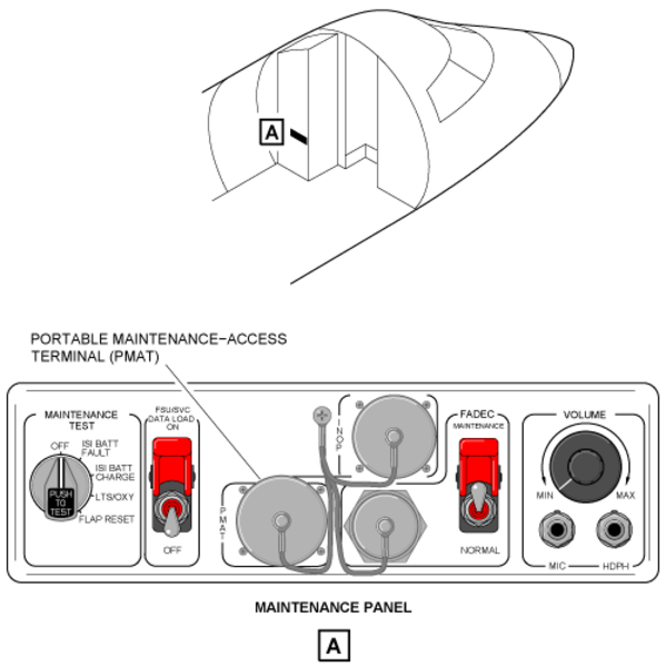
System Test
An initiated built-in test (IBIT) can be done with the rotary test switch on the MAINTENANCE TEST control-panel. The switch is set to the FLAP RESET position. When the test switch is momentarily pushed (approximately 1 second), it starts the same test as the power-up built-in test (PBIT).