


Overview
The fuel feed system supplies pressurized fuel to the engines and APU.
The engine/APU feed and motive flow lines between the collector tank wall and the engine/APU firewall are contained in sealed shrouds which are drained and vented overboard.
For engine start-up, each engine is supplied independently from boost pumps operated by DC-powered motors (DCMs). Primary ejectors supply the fuel when the engines are operating. Fuel is supplied through feed lines, check valves and shutoff valves (SOVs). Scavenge ejectors keep the collector tanks full of fuel, to prevent entry of air into the fuel feed system.
Access to the components inside the collector tank is through the wing tank access panels and then through collector tank access panels in the front wall of the collector tanks at stringer 9.
Primary Ejector Pump
gA primary ejector pump is installed in both the left and right collector tank. It is found in the center, on the bottom of the tank. It is a venturi-type ejector tube driven by the motive flow from the left and right engine. The ejector pump becomes fully operational when the motive flow line pressure reaches 260 psi±30 psi (1861.58 kPa±207 kPa). The ejector pump can supply fuel to the engines and/or APU at a pressure of 9.5 to 11.5 psi (65.5 to 79.3 kPa).
The ejector suction inlet is located at the bottom of the tank. A metal mesh screen around the pickup port prevents the ingestion of foreign particles. The primary ejector pump has a check valve which prevents reverse flow of fuel into the ejector. Also, the check valve has a port to relieve excess pressure back into the collector tank.

Primary Ejector Pressure Sensor
The left and right primary ejector pump each has a pressure sensor that monitors pressure conditions at the outlet of each primary feed ejector. The sensor is a pressure-sensitive captor connected to an electrical contact. The sensors are located on the aft wall of the collector tank on the left and right side. They can be accessed without entering the collector tank. When fuel pressure goes below 4.5 psi (31.03 kPa), the contact in the sensor closes. This sends a low-pressure signal to the remote data concentrator (RDC) and starts the related DC boost pump.

DC Boost Pump Cartridge
One DC boost pump cartridge is in the DC boost pump canister. The DC boost pump cartridge can be removed without draining the fuel tank. Access is through the access panels on the underwing fairing. It is an electrically operated impeller-type pump. It is composed of a 28 VDC brushless motor, an impeller, and a hall effect rotation detector within the motor. The left boost pump cartridge gets power from the left essential bus. The right boost pump cartridge gets power from the right essential bus.
The dc boost pumps provide pressurized fuel during engine start, and APU start when the right engine is not operating. DC boost pumps are also used for engine feed in case of a primary feed ejector failure, and lateral balance of fuel load, through the transfer of fuel from wing to wing. The boost pump can supply fuel at a pressure of 13.8 to 24.2 psia (95.15 to 166.85 kPa).
If the primary ejector and DC boost pump both fail, the respective engine and/or APU would not receive positive pressure from the fuel system. In this case, operation would continue by suction feed from the engine and/or APU fuel pumps.


DC Boost Pump Canister
The dc boost-pump canister is a container for the dc boost pump cartridge. The canister is installed on the bottom skin of each collector tank, just forward of the center of the tank. The boost-pump canister lets the operator remove the dc boost pump cartridge while there is fuel in the fuel tanks. A drain plug lets the operator drain fuel out of the pump canister before removing the cartridge. The canister is composed of an inlet screen, an output port, a check valve, a spring-loaded canister inlet valve and an electrical feed connector. The canister inlet valve is located between the cartridge and the inlet screen. It closes under spring pressure during cartridge removal.

DC Boost Pump Pressure Sensor
The left and right dc boost-pump each has a pressure sensor that monitors pressure conditions at the outlet of each dc boost pump. The sensor is a pressure-sensitive captor connected to an electrical contact. The sensors are located on the aft wall of the collector tank, on the left and right side. Access is through the access panels on the under-wing fairing. They can be accessed without entering the collector tank. The sensor detects pressure at the outlet of the boost pump to indicate the status of the pump and sends a signal to the DCU.

Scavenge Ejector Pump
One scavenge ejector pump is installed on the bottom skin of each wing tank, just forward of the collector tank. Access to the scavenge ejector pump is through the wing tank access panels between ribs 0 and 1. It is a venturi-type ejector tube driven by the motive flow coming from engine. The scavenge pump supplies fuel to the collector tank at a pressure of 2.5 psi (17.24 kPa). The ejector suction inlet is located at the bottom of the tank. A metal mesh screen around the pickup port prevents the ingestion of foreign particles.

Engine Feed Shutoff Valve
Two engine feed SOVs are installed on the inside face of the collector tank aft wall, located forward of the engine debris zones. It is a motor-operated ball valve. When an open/close signal is supplied to the valve motor, the motor turns the ball and opens or closes the valve. This starts/stops fuel flow through the engine feed line. The engine feed SOV is equipped with a thermal-relief valve. This valve allows a fuel overpressure between the SOV and the engine (due to fire or engine failure) to be relieved back to the wing tank.

Engine Feed Shutoff Valve Actuator
An actuator is on each engine feed SOV. It opens and closes the valve with a DCM. The actuator is outside of the fuel tank and can be replaced without draining or entering the tank. The left engine feed SOV actuator gets 28 VDC from the L BATT BUS. The right engine feed SOV actuator gets 28 VDC from the R BATT BUS.

APU Feed Shutoff Valve
One APU feed SOV is installed on the inside face of the collector tank aft wall, located forward of the engine debris zones. It is a motor-operated ball valve. When an open/close signal is given to the valve motor, the motor turns the ball and opens or closes the valve. This starts/stops fuel flow in the APU feed line. The APU feed SOV is equipped with a thermal-relief valve. This valve allows a fuel overpressure between the SOV and the APU (due to fire or APU failure) to be relieved back to the wing tank.

APU Feed Shutoff Valve Actuator
An actuator is on the APU feed SOV. It opens and closes the valve with a DCM. The actuator is outside of the fuel tank and can be replaced without draining or entering the tank. The APU feed SOV actuator gets 28 VDC from the L ESS BUS.

APU Fuel Feed Line
The APU fuel feed line moves fuel from the collector tanks to the APU. The line is a rigid molded type that can contain fuel at a maximum temperature of 150 °C (302 °F) and a pressure of 50 psi (344.74 kPa).
Engine Feed Check Valve
iOne engine feed check valve is in each engine feed line. It is located between each DC boost pump and primary ejector pump, after the connection with the wing transfer SOV. The check valve prevents fuel flow back through the primary ejectors when the DC boost pumps are operating. It also prevents fuel flow through the transfer line when the ejectors supply fuel to the engines and/or APU.

Fuel Supply Line
The fuel supply lines move fuel from the collector tanks to the engine fuel supply hoses. The lines are of rigid molded type that can contain fuel at a maximum temperature of 150 °C (302 °F) and a pressure of 50 psi (344.74 kPa).

09/05/18
Fuel Motive Flow Line
The fuel motive flow lines move fuel from the engine fuel motive flow hoses to the primary and scavenge ejector pumps. These lines supply the pressurized fuel necessary for correct operation of the ejectors. They are of rigid molded type that can contain fuel at a maximum temperature of 150 °C (302 °F) and a pressure of 975 psi (6,772.39 kPa).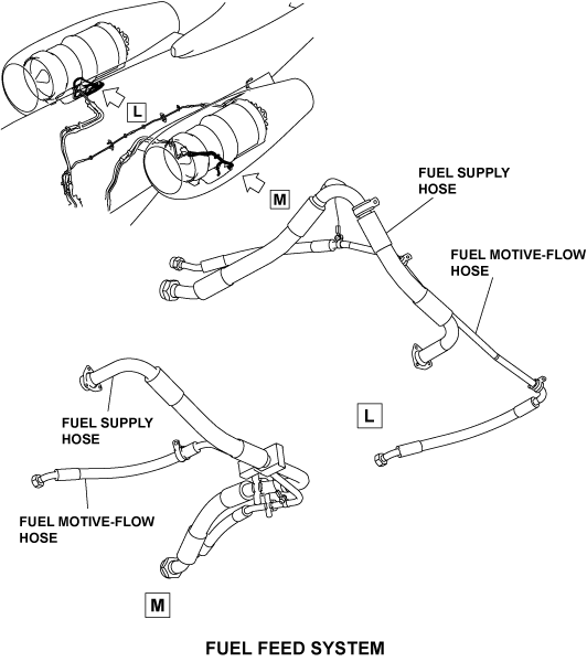
03/30/22
System Operation
Auto Mode
When the L PUMP and/or R PUMP rotary switches on the fuel control panel are set to AUTO, the fuel feed system operates in automatic mode. If an ejector pump fails in automatic mode, low pressure in the feed line causes the related DC boost pump to start automatically. When the boost pump comes on, a L(R) FUEL PUMP ON status message is shown on the EICAS.
Manual Mode
The L PUMP and R PUMP rotary switches can be manually set to OFF or ON, as necessary.
APU Fuel Feed
The right boost pump supplies fuel to the APU when the engines are off. When the engines are operating, the right primary ejector pump supplies fuel for the APU.
When RUN is selected on the APU control panel, a signal is sent from the APU engine control unit to open the APU feed SOV and start the right boost pump. Fuel goes to the APU through the APU feed SOV and APU fuel feed line.
If the APU SOV fails to open or close on command, a signal is sent to the DCU. The DCU sends this data to the EICAS, which displays an APU FUEL SOV FAIL caution message.
Engine Fuel Feed
When the L(R) ENGINE toggle switch on the throttle quadrant is set to RUN, a signal is sent from the full authority digital engine control (FADEC) system to open the left (right) engine feed SOV and start the left (right) boost pump. This supplies fuel to the left (right) engine through the fuel feed line. When the left or right boost pump comes on, a L(R) FUEL PUMP ON status message is shown on the EICAS.
As the fuel pressure in the motive flow line increases, the primary ejector pump begins to operate. The boost pump shuts down automatically when the pressurized fuel supplied by the ejector pump can sustain engine operation. When the left or right boost pump goes off, a L(R) FUEL PUMP OFF status message is shown on the EICAS.
If either engine feed SOV fails to open or close on command, a signal is sent to the DCU. The DCU sends this data to the EICAS, which displays a L(R) ENG FUEL SOV FAIL caution message. If the left or right boost pump fails, a signal is sent to the DCU, which shows a L(R) FUEL PUMP FAIL caution message on the EICAS. If the left or right primary ejector fails, a L(R) FUEL EJECTOR FAIL caution message is shown on the EICAS.
Fuel Flow Shutdown
Pressing the L ENG FIRE, APU FIRE, or R ENG FIRE pushbutton annunciator (PBA) on the engine control panel closes the related feed SOV, which cuts fuel flow to the APU or either engine. The engine feed and APU feed SOVs are equipped with thermal relief valves which allow a fuel overpressure between the SOVs and the engines and/or APU (due to fire or engine failure) to be relieved back to the wing tank.
The DCU sends a L(R) ENG FUEL SOV CLSD status message for display on the EICAS when the left (right) engine feed SOV closes.
The components of the fuel feed system are graphically shown on the fuel synoptic page. In usual operation, the pumps, ejectors, hoses, and SOVs are displayed in green. If a component fails, it is shown in amber. When a component is not in operation, it is shown in white. If the APU ECU or the FADEC system senses an invalid input, a signal is sent to the EICAS to display the affected component in magenta.
The rate of fuel flow is shown in the engine indicating system area of the EICAS. The EICAS messages that follow are related to the fuel feed system:
| EICAS MESSAGE(S) | LEVEL (COLOR) |
|---|---|
| APU FUEL SOV FAIL | CAUTION (amber) |
| L ENG FUEL SOV FAIL | CAUTION (amber) |
| R ENG FUEL SOV FAIL | CAUTION (amber) |
| L FUEL EJECTOR FAIL | CAUTION (amber) |
| R FUEL EJECTOR FAIL | CAUTION (amber) |
| L FUEL PUMP FAIL | CAUTION (amber) |
| R FUEL PUMP FAIL | CAUTION (amber) |
| L ENG FUEL SOV CLSD | STATUS (white) |
| R ENG FUEL SOV CLSD | STATUS (white) |
| L FUEL PUMP OFF | STATUS (white) |
| R FUEL PUMP OFF | STATUS (white) |
| L FUEL PUMP ON | STATUS (white) |
| R FUEL PUMP ON | STATUS (white) |


10/15/20
Component Location Index
| Component Location Index | |||
|---|---|---|---|
| IDENT | DESCRIPTION | LOCATION | IPC REF |
| - | PRIMARY EJECTOR PUMP (LH) | ZONE(S) 161AB | 28-21-01 |
| - | PRIMARY EJECTOR PUMP (RH) | ZONE(S) 162AB | 28-21-01 |
| S4 | PRIMARY-EJECTOR PRESSURE SENSOR (LH) | ZONE(S) 182BB | 28-21-05 |
| S5 | PRIMARY-EJECTOR PRESSURE SENSOR (RH) | ZONE(S) 182BB | 28-21-05 |
| B1 | DC BOOST-PUMP CARTRIDGE (LH) | ZONE(S) 182AL | 28-21-07 |
| B2 | DC BOOST-PUMP CARTRIDGE (RH) | ZONE(S) 182AR | 28-21-07 |
| S129 | DC BOOST-PUMP CANISTER (LH) | ZONE(S) 182AL | 28-21-13 |
| S128 | DC BOOST-PUMP CANISTER (RH) | ZONE(S) 182AR | 28-21-13 |
| S155 | DC BOOST-PUMP PRESSURE SENSOR (LH) | ZONE(S) 182BB | 28-21-15 |
| S154 | DC BOOST-PUMP PRESSURE SENSOR (RH) | ZONE(S) 182BB | 28-21-15 |
| - | SCAVENGE EJECTOR PUMP (LH) | ZONE(S) 161AB | 28-21-17 |
| - | SCAVENGE EJECTOR PUMP (RH) | ZONE(S) 162AB | 28-21-17 |
| - | ENGINE-FEED SHUTOFF VALVE (LH) | ZONE(S) 161AB | 28-21-21 |
| - | ENGINE-FEED SHUTOFF VALVE (RH) | ZONE(S) 162AB | 28-21-21 |
| HP3 | ENGINE-FEED SHUTOFF-VALVE ACTUATOR (LH) | ZONE(S) 182BB | 28-21-25 |
| HP2 | ENGINE-FEED SHUTOFF-VALVE ACTUATOR (RH) | ZONE(S) 182BB | 28-21-25 |
| - | APU-FEED SHUTOFF VALVE | ZONE(S) 162AB | 28-21-29 |
| HP4 | APU-FEED SHUTOFF-VALVE ACTUATOR | ZONE(S) 182BB | 28-21-33 |
| - | APU FUEL-FEED LINE | ZONE(S) 320AB | 28-21-34 |
| - | ENGINE-FEED CHECK VALVE (LH) | ZONE(S) 161AB | 28-21-45 |
| - | ENGINE-FEED CHECK VALVE (RH) | ZONE(S) 162AB | 28-21-45 |
| - | FUEL MOTIVE-FLOW HOSE (LH) | ZONE(S) 432BB | 28-21-50 |
| - | FUEL MOTIVE-FLOW HOSE (RH) | ZONE(S) 442BB | 28-21-50 |
| - | FUEL SUPPLY HOSE (LH) | ZONE(S) 432BB | 28-21-50 |
| - | FUEL SUPPLY HOSE (RH) | ZONE(S) 442BB | 28-21-50 |