


Overview
In case of a lateral difference of fuel load, the fuel transfer system transfers fuel from one tank to the other via boost pumps or through the gravity crossflow shutoff valve (SOV). The system can supply the opposite tank with fuel if a feed system fails. The APU is fed from the right tank in usual operation. The transfer system can supply fuel to the APU from the left tank if necessary. Thermal relief (TR) valves control flow rate and provide overpressure protection.

Wing Transfer Shutoff Valve
The wing transfer shutoff valve (SOV) is a ball-type valve which allows fuel to move from one wing tank to the other. It is located inside the left collector tank. It is at the top of the tank near the aft wall and attaches to the wing transfer SOV actuator. The wing transfer SOV is manually selected open from the fuel control panel. It is usually closed to isolate the wings from each other.

Wing Transfer Shutoff Valve Actuator
The wing transfer SOV actuator controls the wing transfer SOV. It opens and closes the valve with a 28 VDC power motor (DCM). When an open/close signal is given to the valve motor, the motor turns the ball to open or close the valve. This starts/stops the transfer of fuel from one tank to the other. The actuator is outside of the fuel tank at the top and can be replaced without draining or entering the tank.

Gravity Crossflow Shutoff Valve
One ball-type gravity crossflow SOV is on the front wing spar. It allows fuel to move from one wing tank to the other by gravity. It attaches to the gravity crossflow SOV actuator. The gravity crossflow SOV is manually selected open from the fuel control panel. It is usually closed to isolate the wings from each other.

10/15/19
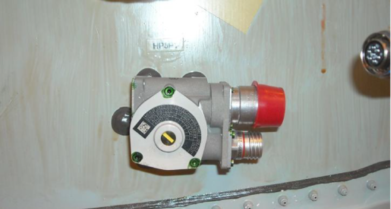
Gravity Crossflow Shutoff Valve Actuator
The gravity crossflow SOV actuator controls the gravity crossflow SOV. It opens and closes the gravity crossflow valve with a DCM. When an open/close signal is given to the valve motor, the motor turns the ball to open or close the valve. This starts/stops the gravity crossflow from one tank to the other. The actuator is located outside of the fuel tank, on the front of the front spar, and can be replaced without draining or entering the tank.

Fuel Control Panel
The fuel control panel is on the central pedestal in the cockpit. The fuel control panel is the interface between the fuel system backup functions and the flight crew. The fuel control panel controls the engine feed system at startup (DC boost pump operation) and during flight if a primary ejector pump fails. The fuel control panel controls the fuel transfer system (wing transfer and gravity SOV operation).

11/13/15
System Operation
Operation of the fuel transfer system is controlled by the aircrew. The fuel quantity for the two wing tanks is shown on the engine indicating system (EIS) area, which informs the aircrew the of the fuel load in each wing tank. A FUEL IMBALANCE caution message is shown on the EICAS display. This message will show after 60 seconds with one of the conditions that follow:
- The fuel load difference is more than 250 lbs between wing tanks when the total fuel load is more than 13,700 lbs
- The fuel load difference is more than 315 lbs between wing tanks when the total fuel load is between 10,000 and 13,700 lbs
- The fuel load difference is more than 450 lbs between wing tanks when the total fuel load is between 4,700 and 10,000 lbs
- The fuel load difference is more than 600 lbs between wing tanks when the total fuel load is less than 4,700 lbs
When the XFER pushbutton annunciator (PBA) on the fuel control panel is pushed, the light comes on and the DC-powered motor (DCM) for the wing transfer SOV is energized, which opens the SOV. When ON is selected on the R PUMP or L PUMP rotary switch, the left or right boost pump is energized. This starts fuel flow through the wing transfer line. Fuel transfers from the heavy tank with the boost pump, through the wing transfer pipe, the wing transfer SOV and the inactive DC boost pump, into the lighter tank. When OFF is selected on the left or right boost pump rotary switches, the left or right boost pump is de-energized. This stops fuel flow through the wing transfer line. When the XFER PBA is pushed again, the light goes off and the wing transfer SOV closes.
In usual operation, the boost pump rotary switches are set to AUTO. This allows the boost pumps to come on automatically if a low-pressure condition is detected in the fuel feed system.
The FUEL XFER OPEN status message is displayed on the EICAS when the wing transfer SOV is open. When the left or right boost pump starts, a L or R FUEL PUMP ON status message is shown on the EICAS. When the left or right boost pump stops, a L or R FUEL PUMP OFF status message is shown.
If the wing-transfer SOV is not opened/closed in 5 seconds or less of command signal, a FUEL XFER FAIL advisory message is shown on the EICAS display. Gravity crossflow can be used by the aircrew in this case. When the GRAVITY XFLOW PBA is pushed on the fuel control panel, the light comes on, and the gravity-crossflow valve DCM energizes. This opens the gravity-crossflow SOV and starts fuel flow through the gravity-crossflow line. When the XFER PBA is pushed again, the light goes off and the gravity-crossflow SOV closes.
A FUEL GRAV XFLOW OPEN status message is shown on the EICAS when the gravity-crossflow SOV opens. In the event the gravity-crossflow SOV is not opened/closed in 5 seconds or less of command signal, a FUEL GRAV XFLOW FAIL advisory message is shown on the EICAS display. When the fuel load balance in the wing tanks is restored, a FUEL BALANCED status message is shown to inform the aircrew.
The EICAS messages that follow are related to the fuel transfer system:
| EICAS MESSAGE(S) | LEVEL (COLOR) |
|
FUEL IMBALANCE
|
CAUTION (amber)
|
|
FUEL GRAV XFLOW FAIL
|
ADVISORY (cyan)
|
|
FUEL XFER FAIL
|
ADVISORY (cyan)
|
|
FUEL XFER FAIL
|
ADVISORY (cyan)
|
|
FUEL BALANCED
|
STATUS (white)
|
|
FUEL GRAV XFLOW OPEN
|
STATUS (white)
|
|
L FUEL PUMP OFF
|
STATUS (white)
|
|
R FUEL PUMP OFF
|
STATUS (white)
|
|
R FUEL PUMP OFF
|
STATUS (white)
|
|
L FUEL PUMP ON
|
STATUS (white)
|
|
R FUEL PUMP ON
|
STATUS (white)
|
|
FUEL XFER OPEN
|
STATUS (white)
|
The components of the fuel transfer system are graphically shown on the fuel synoptic page. In usual operation, the pumps and the SOVs are displayed in green. If a component fails, it is shown in amber. When a pump or a flow tube is not in operation, or if an SOV is closed, it is shown in white.

![]()
10/15/20
Component Location Index
| Component Location Index | |||
|---|---|---|---|
| IDENT | DESCRIPTION | LOCATION | IPC REF |
| - | WING-TRANSFER SHUTOFF VALVE | ZONE(S) 161AB | 28-22-01 |
| HP1 | WING-TRANSFER SHUTOFF-VALVE ACTUATOR |
ZONE(S) 182BB | 28-22-05 |
| - | GRAVITY-CROSSFLOW SHUTOFF VALVE | ZONE(S) 161AB | 28-22-07 |
| HP5 | GRAVITY-CROSSFLOW SHUTOFF-VALVE ACTUATOR |
ZONE(S) 181BL | 28-22-08 |
| PL16 | FUEL CONTROL PANEL | ZONE(S) 211 | 28-22-09 |