


Overview
The fuel management and quantity gauging system (FMQGS) collects fuel system data and manages the refuel/defuel system. The FMQGS also generates information for the indication system. Probes in the wing tanks supply fuel quantity and temperature to the fuel quantity computer.
11/13/15
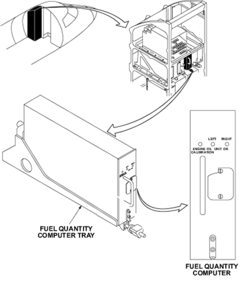
Fuel Quantity Computer
The fuel quantity computer is in the left equipment rack in the forward fuselage. The computer processes fuel gauge and fuel level sensor signals. It also provides fuel quantity, temperature status, and warning and failure condition information, which is stored in nonvolatile memory.
The fuel quantity computer has two microprocessor-based channels on three circuit boards which operate independently. Channel 1 is powered from the left essential bus. Channel 2 is powered from the right main bus. During refuelling, power for both channels is taken from the battery bus.
After computation, the fuel quantity computer sends the fuel quantity (in lbs or kg) for each wing tank and total fuel mass to the remote data concentrator (RDC), a dual-channel expansion unit of the data concentrator unit (DCU). The RDC relays this data to the DCU, which displays it on the EICAS and/or the refuel/defuel control panel.
The fuel quantity computer monitors the refueling/defueling operations. It provides automatic control of refueling when FUEL AUTO is selected on the refuel/defuel control panel.
The fuel quantity computer identifies defective line replaceable units (LRUs) in the FMQGS, including individual tank probes. It allows maintenance testing through an RS422 connection. The computer communicates with the maintenance diagnostic computer (MDC) through the input/output concentrator (IOC).
The fuel quantity computer also measures engine oil level. It calculates the data and sends it to the RDC, for display on the EICAS. The fuel quantity computer has a pushbutton, protected by a guard, which starts calibration of the oil measurement system.
The oil measurement system is independent of the fuel gauging system.
11/13/15
Fuel Quantity Computer-Tray
The fuel quantity computer tray is located in the left equipment rack in the forward fuselage. The computer tray supports the fuel quantity computer.
02/05/24
Fuel Quantity Probes with Compensator
One fuel quantity probe with compensator is located on Rib 1 in each wing tank, forward of the collector tank. The probe consists of two metal concentric tubes, allowing fuel and air between the tubes to act as a dielectric. It uses the relationship between the dielectric constant of the fuel and its density. The probe gives a capacitance signal proportional to the fuel height in the tank. The fuel quantity computer uses this data to compute the total mass of fuel in the collector tanks.
Note: The left and right compensator probes are attached to both Probes 8 LHS and 8 RHS. For Maintenance Diagnostic purposes, the capacitance values derived from the compensator probes is displayed as a 'Probe 10 (PR10)' value.

Fuel Quantity Probe
Eight fuel quantity probes are installed within each wing tank. One probe attaches to the inboard side of rib 1 in the collector tank. Four probes attach to the inboard side of ribs 2, 6, 13, and 16. The other three probes attach to the outboard side of ribs 3, 9, and 11.
The probes are used to compute fuel density, to be applied to the fuel quantity computer reading. The output signal is checked against preset values to detect a probe fault. If a fault is detected, the fuel quantity computer reverts to a standard stored value of density, for mass computation. The probe consists of a metal concentric tube. This structure lets fuel and air act as a dielectric and gives a signal proportional to the fuel height in the wing tank.


High-Level Sensor
The high-level sensor is in each wing tank, attached to the outboard side of Rib 12. It is located at the top of the rib, at the 3% airspace level of the wing tank. It is a thermistor type sensor, that when in contact with fuel, becomes cool and gives a full fuel tank signal. When this happens, a HI LEVEL DETECTOR indication is shown on the refuel/defuel control panel and a signal is sent to the fuel quantity computer. The fuel quantity computer immediately closes the refuel/defuel SOVs to stop the pressure refueling operation. The high-level sensor signal overrides the preselected fuel quantity signal.

Temperature Sensor
One temperature sensor is on the front spar of the right wing tank between Rib 0 and Rib 1. Access to the sensor is through the forward maintenance access panel. It detects low fuel temperature and sends the data to the RDC to warn the flight crew of a fuel icing risk. It has a thermistor embedded in a metallic shell.

03/14/17
System Operation
Information on fuel quantity and system status is supplied to the fuel quantity computer from the fuel probes and sensors. The fuel quantity computer sends this data to the RDC. The RDC relays this data to the DCU, which sends the data for display on the EICAS. The engine indicating system area of the EICAS displays respective wing tank fuel quantity and temperature indications. This information is also displayed on the fuel synoptic page.
When the fuel quantity computer powers up, it performs an initial built-in test (BIT). The computer continuously monitors the fuel system components while the system is on.
When the bulk fuel temperature goes below -38.2 °C, a signal is sent from the temperature sensor to the fuel quantity computer. This data is sent to the DCU, which displays a WING FUEL TEMP LOW caution message on the EICAS. This message is removed when the temperature goes above -37.8 °C.
When the fuel quantity goes below 500 lbs (226.80 kg) in either one of the two wing tanks, fuel probes in the wing tanks send a signal to the fuel quantity computer, which sends the data to the DCU. The DCU sends a FUEL QUANTITY LOW caution message to be displayed on the EICAS. If the fuel level goes below 200 lbs (90.72 kg) in one of the two the collector tanks, a L (R) FUEL COLLECTOR LOW caution message is also shown.
The fuel quantity computer controls and monitors the refueling procedure upon selection of automatic refueling. Pushing a test button on the refuel/defuel control panel starts a refueling test sequence. During automatic refueling, the fuel quantity computer compares the gauge quantity with the preselected quantity and controls the respective refuel/defuel shutoff valves (SOVs) in the refuel manifold.
The fuel synoptic page also displays total fuel used during APU or main engine operation. The counter is reset to zero each time aircraft power is removed and turned on. It can also be reset using the fuel management system (FMS) control panel.
If a failure occurs in the two computer channels in the fuel quantity computer, BIT equipment in the fuel quantity computer detects this and sends a signal to the DCU. The DCU sends a FUEL QUANTITY FAIL caution message to be displayed on the EICAS. If a failure occurs in only one channel, a FUEL QUANTITY FAULT advisory message is shown.
For ground conditions, the fuel quantity probes are calibrated at the normal ground standing angle. To take account of the difference in wing attitude and aircraft acceleration between ground and flight cases, a different characteristic is assumed for flight. The computer changes to flight or ground mode according to a weight-on-wheels (WOW) signal coming from the PSEU. The WOW signal is sent to the IOC, which sends the data to the fuel quantity computer.
In flight, the fuel quantity computer uses a signal from the IOC to correct for aircraft attitudes generated by the Inertial reference system (IRS). A time delay is incorporated before a change in gauge reading to compensate for transient flight. This gives time for the fuel to settle before the updated attitude correction is applied. If the IRS signal is lost in flight, the fuel quantity computer takes in account a default value of 0 degree pitch and roll.
The components of the fuel system are graphically shown on the fuel synoptic page. Total fuel quantity is shown in the top left corner in green. If a low-fuel condition occurs, the fuel quantity is shown in amber. The left and right wing fuel quantities are shown in green inside the left and right wing outlines respectively. These quantities also turn amber in color in a low-fuel condition.
Bulk fuel temperature is shown in green inside the right wing tank outline, above the wing fuel quantity. In low-temperature conditions, it is shown in amber.
When a component is not in operation, it is shown in white.
The EICAS messages that follow are related to the FMQGS:
| EICAS MESSAGE(S) | LEVEL (COLOR) |
|---|---|
|
L FUEL COLLECTOR LOW |
CAUTION (amber) |
|
R FUEL COLLECTOR LOW |
CAUTION (amber) |
|
FUEL QUANTITY FAIL |
CAUTION (amber) |
|
FUEL QUANTITY LOW |
CAUTION (amber) |
|
WING FUEL TEMP LOW |
CAUTION (amber) |
|
FUEL QUANTITY FAULT |
ADVISORY (cyan) |


11/13/15
System Interface
The FMQGS has interfaces with the systems/components that follow:
- Refuel/Defuel Control Panel
- Data Concentrator Unit (DCU)
- Remote Data Concentrator (RDC)
- Engine Indicating and Crew Alerting System (EICAS)
- Input/Output Concentrator Unit (IOC)
- Proximity Sensor Electronic Unit (PSEU)
- Inertial reference system (IRS)
- Maintenance Diagnostic Computer (MDC)
- Oil Indication System
02/05/24
Component Location Index
| Component Location Index | |||
|---|---|---|---|
| IDENT | DESCRIPTION | LOCATION | IPC REF |
| A57 | FUEL QUANTITY COMPUTER | ZONE(S) 221 | 28-41-01 |
| - | FUEL QUANTITY COMPUTER-TRAY | ZONE(S) 221 | 28-41-05 |
| MT13 | FUEL QUANTITY PROBE (NO. 8 )WITH COMPENSATOR PROBE ('NO. 10') (LH) |
ZONE(S) 161AB | 28-41-09 |
| MT14 | FUEL QUANTITY PROBE (NO. 8 )WITH COMPENSATOR PROBE ('NO. 10') (RH) |
ZONE(S) 162AB | 28-41-09 |
| MT1 | FUEL QUANTITY PROBE (NO. 1) (LH) | ZONE(S) 531PB | 28-41-13 |
| MT2 | FUEL QUANTITY PROBE (NO. 1) (RH) | ZONE(S) 631PB | 28-41-13 |
| MT3 | FUEL QUANTITY PROBE (NO. 2) (LH) | ZONE(S) 531LB | 28-41-13 |
| MT4 | FUEL QUANTITY PROBE (NO. 2) (RH) | ZONE(S) 631LB | 28-41-13 |
| MT5 | FUEL QUANTITY PROBE (NO. 3) (LH) | ZONE(S) 531KB | 28-41-13 |
| MT6 | FUEL QUANTITY PROBE (NO. 3) (RH) | ZONE(S) 631KB | 28-41-13 |
| MT7 | FUEL QUANTITY PROBE (NO. 4) (LH) | ZONE(S) 531HB | 28-41-13 |
| MT8 | FUEL QUANTITY PROBE (NO. 4) (RH) | ZONE(S) 631HB | 28-41-13 |
| MT9 | FUEL QUANTITY PROBE (NO. 5) (LH) | ZONE(S) 531FB | 28-41-13 |
| MT10 | FUEL QUANTITY PROBE (NO. 5) (RH) | ZONE(S) 631FB | 28-41-13 |
| MT11 | FUEL QUANTITY PROBE (NO. 6) (LH) | ZONE(S) 531CB | 28-41-13 |
| MT12 | FUEL QUANTITY PROBE (NO. 6) (RH) | ZONE(S) 631CB | 28-41-13 |
| MT17 | FUEL QUANTITY PROBE (NO. 7) (LH) | ZONE(S) 531AB | 28-41-13 |
| MT18 | FUEL QUANTITY PROBE (NO. 7) (RH) | ZONE(S) 631AB | 28-41-13 |
| MT107 | FUEL QUANTITY PROBE (NO. 9) (LH) | ZONE(S) 161AB | 28-41-13 |
| MT108 | FUEL QUANTITY PROBE (NO. 9) (RH) | ZONE(S) 162AB | 28-41-13 |
| MT15 | HIGH LEVEL SENSOR (LH) | ZONE(S) 531LB | 28-41-17 |
| MT16 | HIGH LEVEL SENSOR (RH) | ZONE(S) 631LB | 28-41-17 |
| TC1 | TEMPERATURE SENSOR | ZONE(S) 181BL | 28-41-21 |