


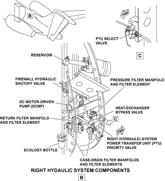
Overview
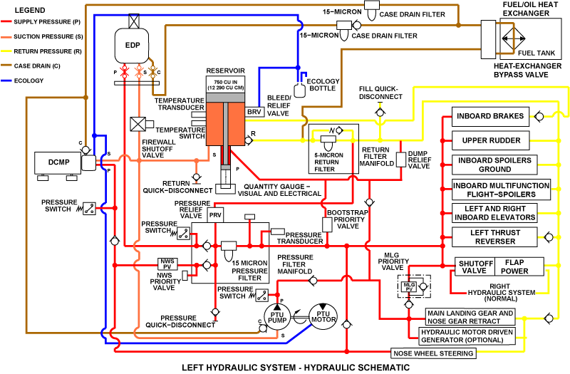
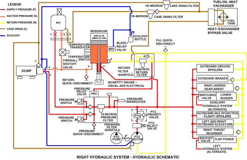
The left and right hydraulic systems are closed (totally independent) closed hydraulic systems. Each of these systems supplies primary and secondary hydraulic pressure to operate the flight controls, landing gear, brakes, nose wheel steering, and thrust reversers.
The left and right hydraulic systems have identical components with exception of Left Hydraulic System Priority valve.
The primary hydraulic power to the left and right systems is supplied through two engine-driven hydraulic pumps (EDPs). Secondary hydraulic power is supplied by two electrical DC motor-driven pumps (DCMPs). Electrical power is supplied to each DCMP by the engine-driven generator on the opposite side of the aircraft. Thus, hydraulic power is kept if there is a one engine malfunction. The DCMPs are energized during flight phases when high flow is necessary and can be operated during ground maintenance with engines off.
In the main hydraulic system, two bootstrap type reservoirs are used. Each reservoir contains two transducers (quantity and temperature) that supply data to the engine indicating and crew alerting system (EICAS) through the remote data concentrator (RDC).
A firewall shutoff valve is installed on the suction line of each EDP. When closed, the firewall shutoff valve cuts off hydraulic fluid flow to the engine area. This occurs when the fire extinguishing system pushbutton annunciator (PBA) of the related engine is manually pushed in on the ENGINE control panel. The firewall shutoff valves are also automatically closed when the related reservoir fluid temperature is more than 275 °F (135 °C). The firewall shutoff valves can be manually closed with the PBAs on the HYDRAULIC control panel.
Pressure transducers and pressure switches are used to monitor and to show system pressures. A pressure switch is installed on each of the EDP, DCMP, and power transfer unit (PTU) pressure lines. The pressure switches are used to supply the EICAS data for the indication of a hydraulic pump or hydraulic system malfunction.
If there is a malfunction of the left EDP, the PTU, supplied with power by the right hydraulic system, can supply pressure to retract the main and nose landing gears. An auxiliary system has a DCMP, an accumulator, and a switching valve. These supply power to energize the lower rudder power control unit (PCU) if there is a malfunction of a right hydraulic system.
The left and right hydraulic systems are carefully installed to prevent the same malfunctions of more than one system. The hydraulic systems are installed with space between the systems. This is necessary in the engine-rotor burst zone to prevent material damage to more than one system from an external source. DC power is supplied to each of the left and right DCMPs in different procedures during different conditions of DC power and hydraulic-system malfunctions. This is to make sure a maximum number of flight controls are available at all times.
11/23/15
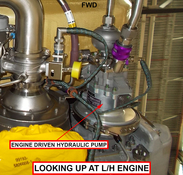
Engine-Driven Hydraulic Pump
The left and right engine-driven hydraulic pumps (EDPs) are installed on the related left and right engine gearbox.
The EDP is a variable-displacement hydraulic pump which has a pressure adjusted supply control with a continuous adjustment. It controls the fluid outlet pressure supplied to the system to keep the necessary pressure. Each EDP is flange-mounted with a V-band clamp to its related engine gearbox and is operated by a input shaft with a spline.
The input shaft of the EDP engages with an internal spline in the engine gearbox to operate the pump. Each EDP has two quick-disconnect couplings: one coupling for the suction (inlet) line, one coupling for the case drain line, and one standard fitting for the pressure (outlet) line. The two quick-disconnect couplings are connected directly to the related left or right hydraulic system through the engine-mounted hydraulic hoses.
The case drain port is found on the top side of the pump near the mounting flange. The EDP can be bled of air when the case drain quick-disconnect is disconnected.
The pump rated output is 19.6 U.S. gal/min (74.19 L/min) at a discharge pressure of 2,850 psi (19,650.06 kPa). The pump has an inlet pressure of 45 psi (310.26 kPa), when it operates at 5,803 rpm with an inlet fluid temperature of 107.22 °C (225 °F). The 0-flow discharge pressure is 3,000 psi (20,684.27 kPa). The pump proof pressure can operate at 4,500 psi (31,026.41 kPa) at the discharge port and 500 psi (3,447.38 kPa) at the inlet and case drain ports. The EDP rpm ratio is 0.2125:1 of the engine N2 speed.
The EDP is an axial piston type which has a cylinder barrel and nine pistons. The cylinder barrel contains nine chambers radially found about its center. A piston is in each chamber of the cylinder barrel. The pistons are held by a hold-down plate which operates on the top surface of the hanger subassembly.
While the cylinder barrel turns, the pistons move in and out of their chambers. This causes fluid to be pulled into the inlet port and pushed from the outlet port through a stable valve surface. The moved volume from the pump is controlled by the angle of the hanger plate. The hanger plate angle is controlled by discharge pressure through a compensator valve and stroking piston. Above a set pressure, the hanger plate angle decreases, which causes the moved volume to decrease.


Compensator Valve Operation
The hanger subassembly turns while its angle is controlled by the position of the stroking piston. The illustration shows that the stroking piston is almost fully extended. As a result, the hanger subassembly is put at a very small cam angle, which causes a small output flow. The pump high-pressure discharge fluid then is put in contact with the compensator valve spool.
A high flow demand causes the discharge pressure to decrease. This causes the compensator valve spool to move to the right because of the force from the spring. When the pressure goes to a value given by the spring position, the compensator valve spool opens a port in the sleeve. The compensator valve spool then transmits hydraulic fluid from the stroking piston to the case pressure (return) line. The rate piston then extends because of the force from its spring. This causes the pump hanger subassembly to move to a larger angle while the stroking piston retracts. The higher cam angle increases the flow output, which causes the discharge pressure to increase.
The compensator valve spool compares and measures the volume of fluid that goes to the stroking piston to the change in pump output. The flow demand decreases and the discharge pressure increases above the compensated value. When this occurs the compensator valve spool lets the fluid flow to extend the stroking piston. This causes the hanger to decrease the cam angle and the discharge pressure to decrease.

05/13/21
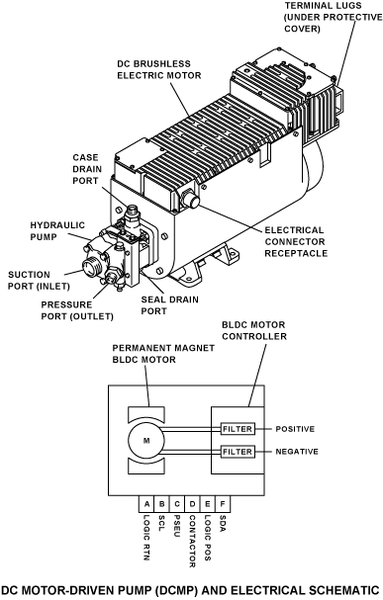
DC Motor-Driven Pump
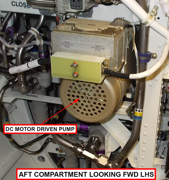
The left and right DC motor-driven pumps (DCMPs) are installed on the left and right side of the fuselage at FS690.00 (WL98.00).
Each DCMP has a variable-displacement hydraulic pump that is attached to a DC electrical motor. The DC electrical motor operates the pump. The pump output increases or decreases to keep the necessary system pressure.
The DCMPs have pressure (outlet), suction (inlet), and case drain ports which are directly connected to the aircraft hydraulic system through hoses. Each DCMP also has a seal drain port which is connected through plastic tubes to the related ecology bottle. Electrical power for the motor is transmitted through an electrical connector which connects with the aircraft wiring harness.
The left DCMP is energized through the R MAIN BUS through circuit breaker HYDRAULIC L DC PUMP (CB2-C11).
The right DCMP is energized through the L ESS BUS through circuit breaker HYDRAULIC R DC PUMP (CB1-C11).
Brushless DC Motor
The DCMP is driven by a 28 VDC, air cooled, explosion-proof, fan-cooled brushless motor. The DCMP meets all performance requirements when supplied with aircraft electrical power with characteristics defined in MIL-STD-704. The DC Electric Motor is an air-cooled design capable to convert applied voltages from 16 VDC to 29 VDC into mechanical energy to drive the hydraulic pump. The DC electric motor contains terminal studs through which electrical power can be transmitted. The motor assembly integrates a controller that is mounted directly on the motor housing that contains capacitor and inductor filters for Radio Frequency and EMI noise abatement.
A D38000/24FB96PN electrical connector connects to aircraft circuitry in order to disable power to the motor when specific failure modes are detected. The logic portion of the DCMP is always powered so that the health of the DCMP can be monitored. If this logic circuitry detects an issue with the DCMP, the controller will stop operation of the motor by interrupting the control signal that operates the DCPC power bus relay.
Hydraulic Pump
A DC motor-driven hydraulic pump has the same mechanical operation as the EDP but it is operated by an electric motor. The hydraulic pump has a pressure-adjusted supply control with a continuous adjustment. It controls the fluid outlet pressure supplied to the system to keep the necessary pressure. The pump is an axial piston type with a cylinder barrel that includes nine pistons. The operation of the pump is the same to that of the EDP.
The compensator valve is also almost the same to that in the EDP. The pump proof pressure can operate at 4,500 psi (31,026.41 kPa) at the discharge port and 500 psi (3,447.38 kPa) at the inlet and case drain ports.

DC MOTOR-DRIVEN PUMP (DCMP) - COMPONENT LOCATION - LEFT HYDRAULIC SYSTEM
11/29/17
Reservoir
The left and right hydraulic system reservoirs are installed, in the aft equipment compartment, on the related left and right hydraulic system racks at FS680.00 (WL127.00).
The reservoir for the left hydraulic system has a capacity of 750 in (12,290.30 cm). The fluid volume for the left hydraulic system reservoir is 3.25 U.S. gal (12.30 L).
The reservoir for the right hydraulic system has a capacity of 525 in (8,603.21 cm). The fluid volume for the right hydraulic system reservoir is 2.27 U.S. gal (8.60 L).
The reservoirs are bootstrap-type which use system high-pressure fluid acting on a piston to provide control of hydraulic system return pressure. Each reservoir supplies the necessary fluid volume required by the related hydraulic system which includes pressurization of the related EDP and DCMP inlets.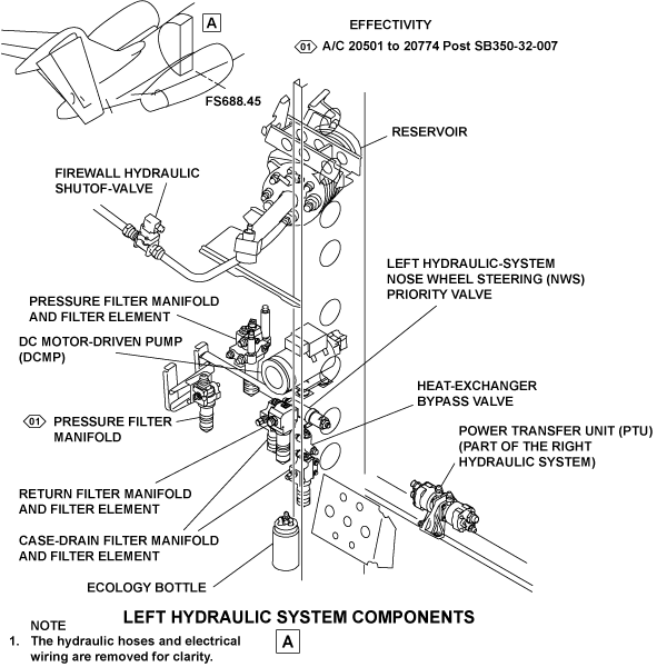
Each reservoir includes the parts that follow:
Low-Pressure Storage Chamber
A low-pressure storage chamber that includes a low-pressure piston is operated by a bootstrap piston to give a chamber pressure of 55±7 psi (379.21±48.26 kPa). The chamber pressure is constant to a maximum of 18 U.S. gal/min (68.14 L/min) through a fluid temperature range of 20 to 225 °F (-6.67 to 107.22 °C). O-rings are used for all dynamic seals for leakage control. Leakage will not be more than one drop in 50 full travel operations of the piston.
The low-pressure storage chamber, related fittings, and components are approved for 150 psi (1 034.21 kPa) with a burst pressure of 300 psi (2 068.43 kPa).
Bootstrap Cylinder
The bootstrap cylinder includes a pressure inlet port and a bootstrap piston. The piston gets pressure,which is usually 3 000 psi (20 684.27 kPa) from the related left or right hydraulic system. This pressure supplies the force to move the low pressure piston and pressurize the reservoir.
Ports
There are two ports on the reservoir for the installation of the temperature switch and temperature transducer.
Bleed/Relief Valve
A bleed/relief valve has a manual fluid bleed function and a pressure relief function. Maintenance personnel have access to the bleed/relief valve which is manually operated by a lever. With a reservoir pressure of 55 psi (379.21 kPa), the force of 3 to 12 lb (1.36 to 5.44 kg) is necessary to push the lever to operate the valve. When the lever is pushed, the caught air is released and the hydraulic fluid is bled into the ecology bottle. When released, the lever automatically goes back to the closed position.
Visual Quantity Indicator
A visual quantity indicator is installed at the end of the bootstrap cylinder on the opposite side of the electrical connector receptacle. The visual quantity indicator is a gauge that shows the hydraulic fluid level in the low-pressure storage chamber with marks from 0 to 100% (10% increments). The visual quantity indicator senses the position of the low-pressure piston by the volume of the remaining fluid. The quantity indicator also sends electrical output signals to the RDC, which shows fluid quantity data on the HYDRAULIC synoptic page of the EICAS.


Suction Shutoff-Valve
A suction shutoff-valve is installed in the suction port of the each reservoir. The suction shutoff-valve is closed by the reservoir piston when the fluid level is almost empty. The fluid flow out of the reservoir is stopped when the piston head touches the spring-loaded seal seat of the valve. The suction shutoff valve stops the hydraulic fluid flow out of the reservoir during the last 0.10 in (2.54 mm) of the storage-chamber piston travel. At this condition, the remaining fluid in the reservoir (but not available to the pressure system) will be of 1.1% for the left and 0.8% for the right reservoir. This prevents the movement of fuel into the hydraulic system if there is a crack in a hydraulic line in the fuel tank.
After the suction shutoff valve closes, the pump will have no fluid. The pump will then vapor lock and stop its operation.

11/23/15
Reservoir Return Line Check Valve
A check valve is installed at the return line port of the left and right system reservoirs. The check valves are used to prevent fluid flow in the opposite direction from the related reservoir to the left and right return filter manifold.

11/23/15
Temperature Switch
There are a total of four temperature switches installed on the left and right hydraulic systems. There are two temperature switches in the left system, one in the reservoir and the other in the return line to the reservoir. The right system has two temperature switches that are both located in the reservoir. The left (right) temperature switches supply a control signal to the related left (right) hydraulic-reservoir temperature-relay K137 (K138) when the reservoir fluid temperature reaches 275 °F (135 °C). When energized, the left (right) hydraulic-reservoir temperature-relay causes the related left (right) firewall shutoff valve relay K59 (K60) to energize and causes the EDP to depressurize.

03/13/18
Nose-wheel steering Filter-Manifold
On A/C 20745 and SUBS and On A/C 20501 to 20744 Post SB SB 350-32-007
The location of the hydraulic fluid filter is in the aft equipment bay. The filter is installed on the Left Hydraulic System downstream of the DC Motor Pump (DCMP) in the line supplies fluid to the Nose Wheel Steering (NWS). The Engine-Driven Pump (EDP) discharge does not flow through this filter. Only DCMP discharge flows through the filter.
The hydraulic fluid goes into the NWS filter manifold through the three pressure inlet ports. The inlets are pump A, pump B, and the ground pressure ports. Fluid from pump A and pump B inlet ports goes through check valves which prevent opposite fluid direction flow through the manifold. The fluid then flows around the shutoff diaphragm to the outer area of the filter element and through the NWS filter element. It then flows through the center of the shutoff diaphragm and comes out of the manifold through the pressure outlet port.
The NWS filter manifold includes the parts that follow:
Automatic Shutoff Device
An automatic shutoff device which is installed in the filter head at the top of the filter bowl. This shutoff device prevents hydraulic fluid leakage when the filter element is replaced. While the filter bowl is removed, a spring pushes the shutoff diaphragm into the closed position. The automatic shutoff device is resistant to 200 psi (1,378.95 kPa) without leakage (with the bowl and the element removed).
Differential Pressure Indicator
A differential pressure indicator (DPI) gives a visual warning indication (an extended red button) when the pressure filter element must be replaced. The red button on the top of the DPI extends when the differential pressure across the filter element increases to 55±6 psi (379.21±41.37 kPa). When operated, the red button will stay extended until pushed in manually. When the DPI is in the pushed in position (usual operation), the indicator can not be seen (fully retracted).
A surge arrester device in the DPI prevents its accidental operation when there is a flow surge that occurs momentarily.
A thermal lockout device in the DPI makes sure that it is locked out when the hydraulic fluid temperature is less than 85 °F (29.44 °C). When the hydraulic fluid temperature is more than 115 °F (46.11 °C ), the thermal lockout device lets the DPI operate.
The DPI is a cartridge configuration which can be easily removed from and installed on the filter manifold.
On A/C 20745 and SUBS and On A/C 20501 to 20744 Post SB SB 350-32-007
Nose-wheel steering Filter-Element
A Nose Wheel Steering (NWS) filter element is installed, in the aft equipment compartment, in the filter bowl on the NWS filter manifold. The NWS filter element is used to remove solid particle contamination from the fluid flow that comes from the auxiliary DCMP.
The NWS filter element is a 15-micron, disposable type cartridge which is continuously monitored for dirt by the DPI on the related NWS filter manifold. The NWS filter element is of the same type as the left and right hydraulic-systems case-drain filter-elements and is interchangeable.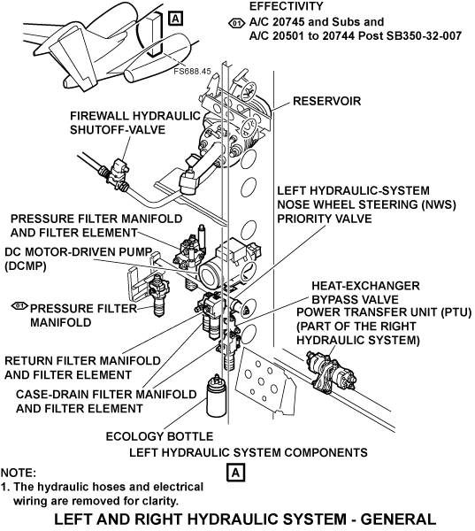
PRESSURE FILTER MANIFOLD AND FILTER ELEMENT - COMPONENT LOCATION - LEFT HYDRAULIC SYSTEM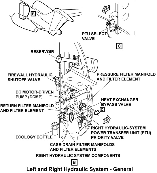


11/23/15
Pressure Relief Valve
A pressure relief valve is installed in each of the pressure filter manifolds. The pressure relief valves are installed upstream from the pressure filter and connected to the return line downstream of the return filter.
The pressure relief valves keep the system supply pressure below 125% of the system pressure. This is to prevent the system from an over pressurization condition if there is a pump or system malfunction. The pressure relief valves have a flow of 18.0 U.S. gal/min (68.14 L/min). The maximum differential pressure that is permitted is 3,600 psi (24,821.12 kPa) at a fluid temperature of 100 °F (37.78 °C).

11/23/15
Return Filter Manifold
A return filter manifold is used for each of the left and right hydraulic systems The return filter manifolds are installed, in the aft equipment compartment, on the related left and right hydraulic system rack at FS691.00 (WL94.00). Each return filter manifold is used, with the return filter element, to remove solid particle contamination from the low-pressure return flow.
The hydraulic fluid goes into the return filter manifold through the pressure inlet port. The fluid then flows around the shutoff diaphragm to the outer area of the filter element and through the return filter element. It then flows through the center of the shutoff diaphragm and comes out of the manifold through the pressure outlet port.
Each return filter manifold includes the parts that follow:
Bypass Relief Valve
A bypass relief valve opens when the return filter element becomes clogged. This lets hydraulic fluid which is not filtered to bypass the clogged filter element. The bypass relief valve has a flow of 14.0 U.S. gal/min (53.00 L/min). The maximum differential pressure that is permitted at this flow is 160 psi (1,103.16 kPa) through the fluid temperature range of 20 to 275 °F (-6.67 to 135 °C). The return filter manifold is made to prevent solid particle contamination to stop the fluid to go through the bypass relief valve.
Automatic Shutoff Device
An automatic shutoff device is installed in the filter head at the top of the filter bowl. This shutoff device prevents hydraulic fluid leakage when the filter element is replaced. While the filter bowl is removed, a spring pushes the shutoff diaphragm into the closed position. The automatic shutoff device is resistant to 200 psi (1,378.95 kPa) without leakage (with the bowl and the element removed).
Differential Pressure Indicator
A differential pressure indicator (DPI) gives a visual warning indication (an extended red button) when the case drain filter element must be replaced. The red button on the top of the DPI extends when the differential pressure across the filter element increases to 70±10 psi (482.63±68.95 kPa). When operated, the red button will stay extended until pushed in manually. When the DPI is in the pushed in position (usual operation), the indicator can not be seen (fully retracted).
A surge arrester device in the DPI prevents its accidental operation when there is a flow surge that occurs momentarily.
A thermal lockout device in the DPI makes sure that it is locked out when the hydraulic fluid temperature is less than 85 °F (29.44 °C). When the hydraulic fluid temperature is more than 115 °F (46.11 °C ), the thermal lockout device lets the DPI operate.
Return Filter Element
A return filter element is installed in the filter bowls on the left and right return filter manifolds. The return filter element is used to remove solid particle contamination from the fluid flow that comes from the low-pressure hydraulic fluid-return-flow before it enters the hydraulic system reservoir. They also filter any return replenishment fluid that comes from the related ground-service fill port
The return filter element is a 5-micron, disposable type cartridge which is continuously monitored for dirt by the DPI on the related return filter manifold.
The filter bowl has standard 0.875 in (22.22 mm) square wrench flats. The filter bowl is torqued on the pressure manifold housing.

RETURN FILTER MANIFOLD AND FILTER ELEMENT - COMPONENT LOCATION - LEFT HYDRAULIC MANIFOLD


11/23/15
Case Drain Filter Manifold
Two case drain filter manifolds are used for each of the left and right hydraulic systems (four in total). The case drain filter manifolds are installed, in the aft equipment compartment, on the related left and right hydraulic system rack at FS691.00 (WL87.00). Each case drain filter manifold is used, with the case drain filter element, to remove solid particle contamination from the case drain hydraulic fluid that comes from the related EDP and DCMP.
The hydraulic fluid goes into the case drain filter manifold through the pressure inlet port. The fluid then flows around the shutoff diaphragm to the outer area of the filter element and through the return filter element. It then flows through the center of the shutoff diaphragm and comes out of the manifold through the pressure outlet port.
Each case drain filter manifold includes the parts that follow:
Automatic Shutoff Device
An automatic shutoff device is installed in the filter head at the top of the filter bowl. This shutoff device prevents hydraulic fluid leakage when the filter element is replaced. While the filter bowl is removed, a spring pushes the shutoff diaphragm into the closed position. The automatic shutoff device is resistant to 100 psi (689.48 kPa) without leakage (with the bowl and the element removed).
Differential Pressure Indicator
A DPI which gives a visual warning indication (an extended red button) when the case-drain filter element must be replaced. The red button on the top of the DPI will extend when the differential pressure across the filter element increases to 18.5±3 psi (127.55±20.68 kPa). When operated, the red button will stay extended until pushed in manually. When the DPI is in the pushed in position (usual operation), the indicator can not be seen (fully retracted). A surge arrester device in the DPI prevents its accidental operation when there is a flow surge that occurs momentarily.
A thermal lockout device in the DPI makes sure that it is locked out when the hydraulic fluid temperature is less than 55 °F (12.78 °C). When the hydraulic fluid temperature is more than 85 °F (29.44 °C ), the thermal lockout device lets the DPI operate.
Case Drain Manifold Check Valve
A check valve is installed at the outlet port of the case drain filter manifolds. They are used to prevent reverse flow to the related EDPs and DCMPs.
Case Drain Filter Element
A case drain filter element is installed in the filter bowls on each of the four case drain filter manifolds. Two case drain filter elements remove solid particle contamination from the fluid flow that comes from the two EDPs before it enters the heat exchanger. Two case drain filter elements are used to remove solid particle contamination from the fluid flow that comes from the two DCMPs before it enters the heat exchanger.
The pressure filter element is a 15-micron, disposable type cartridge which is continuously monitored for dirt by the DPI on the related pressure filter manifold. The pressure filter element is of the same type as the auxiliary hydraulic systems pressure filter elements. These elements are interchangeable. The filter bowl has standard 0.875 in (22.22 mm) square wrench flats. The filter bowl is torqued on the pressure manifold housing.

CASE-DRAIN FILTER MANIFOLDS AND FILTER ELEMENTS - COMPONENT LOCATION - LEFT HYDRAULIC SYSTEM


11/23/15
Firewall Hydraulic Shutoff Valve
A firewall hydraulic shutoff-valve (SOV) is used for each of the left and right hydraulic systems. The firewall hydraulic SOVs have two parts. They are the firewall hydraulic shutoff-valve and the firewall hydraulic shutoff-valve-actuator. They are installed at FS708.00 (WL124.00) near the pylon area and below the related left and right hydraulic system reservoirs. The two firewall hydraulic shutoff-valves are installed on each EDP suction line.
If there is a fire, the shutoff valves can be closed to stop hydraulic fluid flow to the engine area. The valve closes when the pilot manually arms the engine fire-extinguishing system. The firewall hydraulic shutoff valves can also be manually closed independently of the fire extinguishing system. This is done when the related L SOV CLOSED or R SOV CLOSED pushbutton, on the HYDRAULIC control panel, is pushed. The firewall hydraulic shutoff valves are also automatically closed when the temperature switch senses a fluid temperature of more than 275 °F (135 °C).
The left firewall hydraulic shutoff valve is energized through the L BATT BUS through circuit breaker L HYD SOV (CB1-C10).
The right firewall hydraulic shutoff valve is energized through the R BATT BUS through circuit breaker R HYD SOV (CB2-C9).
Each firewall hydraulic shutoff valve includes the parts that follow:
Motor-Operated Valve
An electric motor-operated actuator is installed on a ball valve (valve body). It has two positions, which are OPEN and CLOSED, with no positions in the middle. The motor operates through a set of gears which moves a ball valve through a 90 degrees. The ball valve moves from fully open to fully closed, or in the opposite direction. The OPEN and CLOSED positions are a permanent label on the valve housing.
An indicator arm moves with the ball valve through a 90 degrees arc to align with the OPEN and CLOSED marks on the valve housing. The indicator arm cannot open or close the ball valve manually. The ball valve gives free hydraulic flow when it is open and blocks flow when it is closed.
Thermal Relief Valve
A thermal relief valve is in the firewall hydraulic SOV to give protection if the downstream pressure is more than 100 psi (689.48 kPa). The high pressure is caused when the firewall hydraulic SOV is in the CLOSED position and there is thermal expansion. The thermal relief valve lets a small quantity of flow, from the outlet to the inlet, to bypass the ball valve. A differential pressure of 60.0 psi (413.69 kPa) minimum is necessary to set the relief valve.
Relay
A two-pole, two-throw relay controls the direction that the motor turns. When there is no electrical power, the relay switches are in the OPEN position. A CLOSE command is manually set by the pilot. Then the relays set the switch to the opposite pole and the motor turns in the direction to close the valve.
Microswitches
There are four microswitches in the firewall hydraulic SOV which are controlled by cams while the ball valve turns through its 90 degrees arc of movement.
Two microswitches control how far the motor turns. When the valve ball gets to the end of its travel, the switches open to stop the current to the motor.
The other two microswitches show the valve position (open or closed) on the EICAS. During the valve open cycle, the contacts of the open-position indication switch close (to ground) when the valve ball gets to 86 degrees open. The closed position indication switch operates during a closed cycle of the valve. Its contacts close when the valve ball is in 4 degrees of the fully closed position.
Firewall Hydraulic Shutoff-Valve-Actuator
The data on the firewall hydraulic shutoff-valve-actuator is found below the title of the Firewall Hydraulic Shutoff-Valve.

FIREWALL HYDRAULIC SHUTOFF-VALVE - COMPONENT LOCATION - LEFT HYDRAULIC SYSTEM


Inline Check Valves
Inline check valves are used in the left hydraulic system lines that follow:
- PTU pump case drain discharge line
- Thrust reverser return line
- Inboard brakes return line
- Main and nose landing gear retract and nose wheel steering return line
- Nose wheel steering pressure line
- DCMP pressure line
Inline check valves are used on the right hydraulic system lines that follow:
- PTU motor case drain discharge line
- Thrust reverser return line
- Outboard brakes return line
- Main landing gear assist return line
These valves make sure that the fluid flows in one direction to prevent damage to components from the opposite flow of fluid.


Left Hydraulic-System NWS and Bootstrap Priority Valve
The left hydraulic-system NWS priority valve is installed in the aft equipment compartment on the left side at FS688.00 (WL89.00). The left hydraulic-system bootstrap priority valve is installed in the aft equipment compartment on the left side at FSXXX.00 (WLXX.00).
The NWS priority valve is a balanced type relief-valve which controls the fluid flow as a function of the inlet pressure. The NWS priority valve is used to stop the hydraulic fluid flow from the left DCMP to the left hydraulic system and direct it to the NWS if the left system flow demand exceeds the DCMP capacity. This will keep the left DCMP pressure on the nose wheel steering circuit.
The bootstrap priority valve is a balanced type relief-valve which controls the fluid flow as a function of the inlet pressure. The bootstrap priority valve is used to trap bootstrap pressure when the Left system is shutdown.
If the inlet pressure to the priority valve decreases to 2,250 psi (15,513.20 kPa), the valve starts to close. At 1,800 psi (12,410.56 kPa), the valve is closed.


11/23/15
Heat Exchanger
A heat exchanger is used for each of the left and right hydraulic systems. They are installed in the wing fuel tanks at LBL20.00 and RBL20.00. The heat exchangers transmit the heat from the case drain hydraulic fluid to the aircraft fuel. This decreases the temperature of the pump case drain fluid before it goes back to the reservoir.
The heat exchangers have a series of aluminum alloy tubes that go in loops which attach to a flange. The flange is attached to the bulkhead of the fuel tank with six fasteners. The mounting flange has a seal groove with a packing. The packing is compressed against the fuel tank bulkhead. This satisfactorily isolates the outer and inner fuel tank. The packing is a part of the heat exchanger assembly. The exchanger heat rate properties for typical flow rates through the heat exchanger tubes when the fuel temperature is 110 °F (43.33 °C) are shown in the table below.
Exchanger Heat Rate Properties
| FLUID FLOW RATE | INLET FLUID TEMPERATURE | EXCHANGER HEAT RATE |
|---|---|---|
| 0.9 U.S. gal/min (3.41 L/min) | 214 °F (101.11 °C) | 121 BTU/min |
| 2.2 U.S. gal/min (8.33 L/min) | 231 °F (110.56 °C) | 260 BTU/min |
| 3.9 U.S. gal/min (14.76 L/min) | 226 °F (107.78 °C) | 318 BTU/min |


05/13/21
Heat Exchanger Bypass Valve
A heat exchanger bypass valve is used for each of the left and right hydraulic systems. They are installed at FS689.00 (WL88.00) between the heat exchanger inlet and outlet lines. The thermostatically controlled bypass valves control the flow of the pump case drain fluid to the heat exchanger as a function of the fluid temperature. The valve also has a pressure relief function to let fluid bypass the heat exchanger if the pressure drop through the heat exchanger becomes too much. At fluid temperatures more than 125 °F (51.67 °C), he valve is in the fully open mode. In the fully open mode, all case drain fluid is sent through the heat exchanger to decrease the temperature. In the fully open mode, with an inlet pressure of 90 psi (620.53 kPa), the internal leakage from the valve inlet to the valve outlet is not more than 12.20 in/in (200 cm/min).
When in the fully open mode, the valve also operates as a pressure relief valve. It permits fluid flow to go directly from the inlet to the outlet port if the pressure drop across the valve increases above 85 psi (586.05 kPa) due to an obstruction in the heat exchanger.
At fluid temperatures less than 95 °F (35 °C), the valve is in the bypass mode. In the bypass mode the valve sends all case drain fluid around the heat exchanger and directly to the reservoir. Internal leakage for the path from the inlet port to the heat exchanger is not more than 1 U.S. gal/min (3.79 L/min). In the bypass mode, the flow that goes from the inlet to the outlet port is 5 U.S. gal/min (18.93 L/min).

HEAT-EXCHANGER BYPASS VALVE - COMPONENT LOCATION - LEFT HYDRAULIC SYSTEM

11/23/15
Ecology Bottle
An ecology bottle is used on each of the left and right hydraulic systems. They are installed, in the aft equipment compartment, at FS696.00 (WL83.00). The ecology bottles collect hydraulic fluid leakage from the related DCMP shaft seals and the reservoir bleed/relief valves.
The ecology bottles are made of environmental stress crack-resistant (ESCR) plastic. The plastic is clear which lets the fluid quantity be seen when the bottle is closed and installed. Each bottle includes two inlet tubes that let the hydraulic fluid collect from the related DCMP shaft seal and reservoir bleed/relief valve. An overflow tube is also installed for an overboard vent. The ecology bottle has a fluid capacity of 24 fl oz (709.76 mL).

ECOLOGY BOTTLE - COMPONENT LOCATION - LEFT HYDRAULIC SYSTEM

05/13/21
Power Transfer Unit
The power transfer unit (PTU) is installed in the aft equipment compartment at FS685.00 (WL82.00) between the left and right hydraulic system components. The PTU has a dry weight of 10.1 lb (4.58 kg) and is electrically bonded between each of its unit fittings and aircraft attachment points. It is a fixed-displacement and a one-direction pump which supplies hydraulic power to the left hydraulic system, through a mechanical shaft, from the right system. The hydraulic fluid is not transferred or mixed between the two systems.
The right hydraulic system operates the motor-side of the PTU, which operates the pump-side of the PTU for the left hydraulic system. The pump-side of the PTU has a case drain port to control the fluid temperature.
The PTU mode of operation (off, automatic, or on) is set through the PTU switch, which is found on the HYDRAULIC control panel. The PTU switch has three positions which are OFF, AUTO, and ON. In the AUTO mode, the control logic of the PTU will energize the PTU select valve when all of the conditions that follow exist:
- The aircraft is in the air
- The landing gear is not in its commanded position
- The hydraulic pressure from the left EDP is low or the left engine is not in operation
- The hydraulic pressure from the right EDP is high.
In addition, if the HMDG is installed, the PTU will run in AUTO mode if the Left engine or EDP are failed, the Right EDP is supplying pressure, no generators are available and the flaps are retracted.
If the PTU is set to ON, the PTU operates when there is sufficient power from the right hydraulic system. If the pressure of the right hydraulic system is low, the balanced relief valve restricts the flow to the motor of the PTU.
If the PTU is set to OFF the PTU will not operate.
The PTU has two sections. Each section is fixed displacement, with an axial piston group. The two sections are separate and connected by a drive shaft. The motor-side is slightly larger in displacement than the pump-side to make up for mechanical losses within the unit while maintaining system pressure. The pump-side includes a case drain port to send internal leakage, idle bypass, and relief valve flow back to the reservoir. The idle bypass flow lets the PTU operate smoothly and continuously at all necessary flows from zero to system pressure. The idle speed of the pump at zero demand flow is approximately 500 rpm.
The PTU pump and the PTU motor include nine piston chambers of a 0.323 in. (8.20 mm) diameter about a chamber circle diameter of 1.154 in (29.31 mm). The set cam angle of the PTU motor side is 20 degrees which gives a displacement of 0.31 in³ (5.08 cm³) for each turn cycle. The set cam angle of the PTU pump side is 18.5 degrees which gives a displacement of 0.285 in³ (4.67 cm³) for each turn cycle. The unit displacement ratio is 1.088:1.


11/23/15
PTU Select Valve
The PTU select valve is installed in the aft equipment compartment at FS684.00 (WL88.00). The PTU select valve is a solenoid-operated valve which controls the flow of hydraulic pressure to the PTU motor. The valve is a 3-way 2-position pilot operated spool valve. The valve is usually closed and pressure-operated to the open position.
The solenoid is energized when the PTU switch on the HYDRAULIC control panel is set to ON, or when the PTU is commanded by the control logic in AUTO mode.
The PTU select valve is energized through the R ESS BUS through circuit breaker HYD PTU (CB2-C10).
The PTU select valve includes the parts that follow:
Solenoid Valve
A solenoid valve which supplies pilot pressure to the main control valve.
Main Control Valve
A main control valve uses the pilot pressure (supplied by the solenoid valve) and spring force to move the main control spool to its open position which lets system pressure go to the valve outlet port. The valve will flow a minimum of 10.0 U.S. gal/min (37.85 L/min) with a pressure of 3,000 psi (20,684.27 kPa) applied at the inlet port. At this condition, the pressure drop across the valve is 60 psi (413.69 kPa) maximum. When there is no pilot pressure, a spring moves the spool valve to the blocked position which sends the cylinder pressure to the return.


11/23/15
Left System - MLG Balanced Relief Valve and Right System - PTU Balanced Relief Valve
The left hydraulic-system main landing gear balanced relief valve is installed on the center line of the aircraft at FS619.00. The right hydraulic-system PTU balanced relief valve is installed in the aft equipment compartment, on the right side of the fuselage at FS687.00. Each balanced relief valve includes a pressure-relief valve that controls the flow of fluid as a function of inlet pressure. The left hydraulic-system main landing gear balanced relief valve controls the flow of hydraulic fluid to the main and nose landing gear. The right system PTU balanced relief valve controls the flow of hydraulic fluid to the PTU.
The balanced relief valve will flow a minimum of 5.0 U.S. gal/min (18.93 L/min) when the pressure at the inlet is 2,450 psi (16,892.15 kPa). If the inlet pressure decreases below 2,450 psi (16,892.15 kPa), the valve will start to close. At 2,200 psi (15,168.47 kPa) the valve has closed.
A check valve lets fluid flow in the opposite direction, with a maximum pressure drop of 100 psi (689.48 kPa) from the outlet to the inlet.


Shock Mount
Four shock mounts are installed below each DCMP. The shock mounts decrease the quantity of vibration and noise transmitted to the aircraft structure.
Each shock mount has a molded rubber isolator held in a metal holder. The isolator is made of a special rubber compound. The metal holder is plated steel for corrosion resistance.
A metal bushing is also molded into the center of the isolator. The bushing moves with the compression loads of the bolt that attaches the isolated component to the shock mount. A snubber washer is used on each side of the shock mount isolator which limit the maximum travel of the isolator.
The maximum rated load of the shock mount at 0.062 in (1.57 mm) movement is 18 lb (8.17 kg).

09/05/18
Engine-Mounted Hydraulic Hoses
Three engine-mounted hydraulic hoses are used on each of the left and right engines. The engine-mounted hydraulic hoses and fittings are connected from the related EDP to the firewall interface connection of the left and right hydraulic systems. The hoses are flexible for easy removal or installation and are installed on the inboard side of the intermediate case.
The fittings at the EDP connection are of the quick-disconnect type. Hoses are held in the engine nacelle with brackets and clamps. The function of the hydraulic hoses and fittings is to supply hydraulic fluid from the EDP to the aircraft hydraulic systems.
There is a suction hydraulic hose, a pressure hydraulic hose, and a case-drain hydraulic hose installed on each engine. The suction hydraulic hose supplies fluid from the reservoir to the EDP. The pressure hydraulic hose supplies fluid from the EDP to the aircraft hydraulic systems, at high pressure. The case-drain hydraulic hose supplies fluid, used to lubricate the EDP, back to the reservoir.
09/05/18
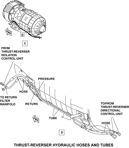
Thrust Reverser Hydraulic Hoses and Tubes
Two thrust reverser hydraulic hoses and tubes are used on each of the left and right engines. The thrust reverser hydraulic hoses and tubes are connected between the related pylon interface connection and the thrust reverser firewall interface-connection. They are installed on the inboard side of each engine with brackets and clamps. The rigid tubes are made from stainless steel. The flexible hoses which attach to each end of the tubes are made from Polytetrafluoroethylene (PTFE) in braided stainless steel. This lets the thrust reverser hydraulic hoses and tubes have an easy removal and installation.
The fittings at the firewall interface connection are of the quick-disconnect type. The function of the thrust reverser hydraulic hoses and tubes is to supply fluid between the pylon interface and the thrust reverser firewall connections. There is a return and a pressure thrust reverser hydraulic hose and tube installed on each of the left and right engines.
The pressure thrust reverser hydraulic hose and tube has a diameter of 0.375 in (9.52 mm). It supplies thrust reverser isolation control-unit pressurized fluid between the pylon interface and the thrust reverser firewall connections. This fluid is then sent to pressurize the thrust reverser directional control-unit.
The return thrust reverser hydraulic hose and tube has a diameter of 0.50 in (12.70 mm). It supplies thrust reverser directional control-unit return fluid between the thrust reverser firewall and the pylon interface connections. This fluid is then sent to the return filter manifold.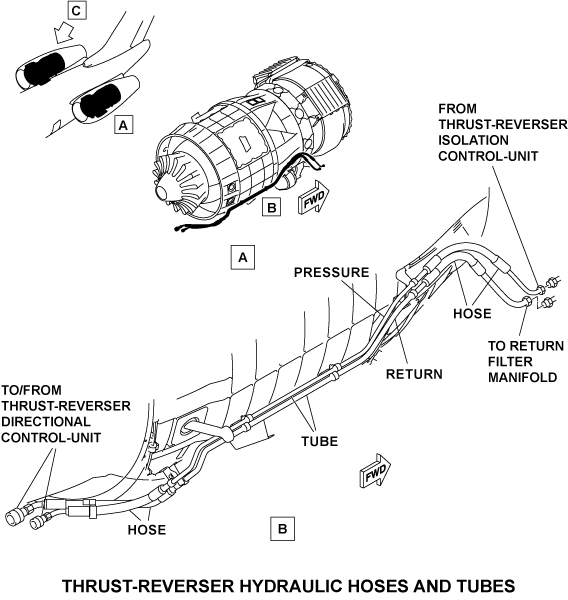
10/24/19
Operation
The hydraulic system supplies pressurized hydraulic fluid to operate the aircraft flight controls, thrust reversers, brakes, and landing gear. The hydraulic fluid is kept in a reservoir. Fluid moves from the reservoir to the hydraulic pumps (EDP and DCMP) with a low bootstrap pressure. The pumps pressurize the fluid in each system to 3,000 psi (20,684.27 kPa) and adjusts output flow to keep a constant system pressure.
The pressurized fluid then flows through a pressure filter which removes particle contamination. This clean, pressurized fluid is supplied to the hydraulic pressurized controls (flight controls, thrust reversers, brakes, landing gear controls).
During operation of hydraulic pressurized controls, hydraulic fluid is sent back to the reservoir through the return lines. The return lines from the flight controls are put together into one fluid return line. This return line sends the fluid through the return filter. The filter removes solid particle contamination before the fluid goes into the reservoir.
Not all of the hydraulic fluid supplied to the pumps is pressurized and sent to the hydraulic-pressurized controls. Some of the fluid flows around the internal components of the pump to absorb heat to prevent a fluid-overtemperature condition. This fluid flows out of the pump through the case-drain line, with low pressure. The hot case-drain fluid then goes through a fuel/oil heat exchanger which decreases its temperature before it goes back into the reservoir.
There are quick-disconnects installed in the system which are used for ground maintenance operations and to fill hydraulic systems. Each of the systems hydraulic pressure and return quick-disconnects are used to operate the related hydraulic system with a ground hydraulic power unit. The left and right system hydraulic fill quick-disconnects are used to add hydraulic fluid to the related reservoir. The left and right hydraulic systems are usually energized by the related EDP. If there is an engine or EDP malfunction, the system affected can be energized through the related DCMP. The left and right DCMPs are energized by the electrical DC bus which is energized by the generator. The generators are installed on the engine opposite the engine that operates the EDP. This configuration lets the two hydraulic systems be energized if there is a one engine malfunction.
The left DCMP is usually energized by the right main DC bus. There is no emergency battery power for the R MAIN BUS. Thus, if there is a malfunction of the right DC generator, the R MAIN BUS can be energized by the left DC generator or the APU. The right DCMP is usually energized by the L ESS BUS which is usually energized by the left engine generator. The L ESS BUS could be energized by the right DC generator or the APU. The L ESS BUS can also be energized through the battery but the battery power supply does not last long. The L ESS BUS can supply power to the auxiliary DCMP for the last minutes of flight, if there is a malfunction of the two engines. Thus, if no generator is in operation, the pilot sets the auxiliary DCMP off until immediately before the landing to keep the battery power available.
If only one generator operates on the aircraft, only one of the left or right DCMPs can operate (one DCMP gets the load shed from the good hydraulic system, and the right DCMP gets load shed before the left DCMP if there is a malfunction in the two EDPs). The auxiliary DCMP does not get the load shed for a one generator operation.
In case of a combination of malfunction that would cause loss of the left and right hydraulic systems, aircraft control is kept by the manual reversion feature of the rudder and elevator control surfaces. The ailerons are strictly mechanical flight controls (through cables and pulleys). Due to the loss of the flaps, thrust reversers, and lift dumping devices, aircraft landing distances will be increased for this malfunction condition. In the event of asymmetric thrust combined with loss of both left and right hydraulic systems, the auxiliary hydraulic system powers the lower rudder to reduce pilot effort to control the asymmetric thrust condition.
The DCMP control logic operates as shown with the clarifications that follow:
- The control keeps the DCMP on for one minute each time that it starts. This prevents an intermittent EDP pressure switch near the DCMP start point.
- There is a five second delay on the signal “ LH DCMP is greater or equal to two generators”. This is to let a small change occur if one engine has a malfunction condition that occurs which causes only one generator to operate (APU is not in operation). If the signal goes back to high before a five second delay, the signal stays high.
- There is a 30 second delay on the weight-on-wheels (WOW) signal to let the DCMP continue operation for 30 seconds after touchdown. This is to keep the necessary hydraulic-pressurized controls energized if one or more EDPs are defective. The WOW signal can go back to air-mode before the 30 second delay elapses. If this occurs, the WOW signal will stay in air-mode and the timer will start again.
- The flap lever position is used to let the backup DCMP automatically start if the flap system has a malfunction (unless a malfunction is caused by the flap lever or the FCU).
- The EDP pressure switches are held in the low pressure position for one minute. This is to prevent starts and stops of the DCMPs caused if the EDP pressure stays too near 1,800 psi (12,410.56 kPa).
When only one aircraft generator operates, only one of the left and right DCMPs operate (except a 5-second transition period when the two DCMPs operate). The right DCMP gets energized before the left DCMP. The auxiliary DCMP automatically operates when the accumulator pressure is low and one of the two engines operates or the aircraft is in a weight-off-wheels condition. If there is no aircraft generator in operation and one or more of the EDPs are not in operation, the DCMPs will not automatically start. This is because the batteries could decrease their power and cannot supply the power to the DCMPs if necessary.
If there is no aircraft generator in operation and the two EDPs are defective, only the right DCMP operates. The right DCMP automatically starts when the flap lever is more than 0 degree and will continue to operate for 30 seconds after touchdown. If the flap lever is at 0 degree, the right DCMP remains off to keep battery power to the maximum.
The pilots can manually select the L (R) DCMP switch ON when it is necessary. This can be done when the related aircraft generators are off-line. For a two generator malfunction, the pilots must manually set the DCMP AUX PUMP switch to OFF to keep the battery power. The DCMP AUX PUMP switch must be set to AUTO a minimum of 30 seconds before flaps deployment. The 20- and 90-second flap timers give sufficient time for the flaps to retract when energized by the right EDP or the right DCMP.


07/14/21
Controls and Display
The DCMPs mode of operation (off, automatic, or on) is set through the L (R) PUMP switch, which is found on the HYDRAULIC control panel. The L (R) PUMP switch has three positions which are OFF, AUTO, and ON. When the selector switch is set to ON, the related DCMP operates in the manual mode (continuous). When the selector switch is set to AUTO, the related DCMP automatically starts when the two conditions that follow exist:
- Flaps are not at the 0 degree position
- At least one aircraft generator is operational
The left and right DCMPs also operate in the automatic mode when the two conditions that follow exist:
- Related selector switch is set to AUTO
- EDP malfunction occurs with the aircraft in a weight-off-wheels condition
When the L (R) SOV PBA on the HYDRAULIC control panel is pushed, and the lamp comes on the legend CLOSED shows. This closes the related firewall hydraulic SOV.
During usual maintenance operation, the selector switches are set to OFF to increase system safety.
The L (R) HYD SOV FAIL caution message will come on when:
- The left (right) hydraulic SOV did not close when one of the conditions that follows occurs:
- The left (right) ENG FIRE switch was pressed
- The left (right) hydraulic SOV switch was set to CLOSED
- The automatic over-temp closure was commanded
The HYD PTU FAIL caution message will come on when the PTU does not operate when the left hydraulic system pressure is ≤1,800 psi.
The L (R) HYD ENG PUMP FAIL advisory message will come on when the left (right) hydraulic EDP does not pressurize the system.
The L (R) HYD DC PUMP FAIL advisory message will come on when the left (right) hydraulic DCMP does not pressurize the system.
The L (R) HYD SOV CLOSED advisory message will come on when the left (right) SOV is closed because of an automatic system command.
The HYD PUMP NOT AUTO status message will come on when at least one HYDRAULIC PUMP (L, R, PTU or AUX) switch is not in the AUTO position.
The L (R) HYD SOV CLOSED status message will come on when the left (right) SOV is closed because of a manual command.
The status of the left and right DCMPs are shown on the HYDRAULIC synoptic page. The left and right DCMPs are shown in a circle with the letter P in it. The contour color is usually the same as the adjacent line. The lines color can be one of those that follow:
- Red to show an unserviceable status
- Yellow to show a caution status
- White to show a usual status with no hydraulic pressure
- Green to show a usual status with hydraulic pressure
- Magenta to show invalid or unknown status
The left and right hydraulic pressure, quantity, and temperature display is shown on the HYDRAULIC synoptic page in color. The white color indicates a correct hydraulic pressure signal >3,200 psi. The green color indicates a correct hydraulic pressure signal >1,800 and ≤3,200 psi. The amber color indicates a correct hydraulic pressure signal ≤1800 psi.
For the left fluid quantity, the white color indicates a correct hydraulic fluid quantity signal 85%. The green color indicates a correct hydraulic fluid quantity signal between 30 and 85%.
For the right fluid quantity, the white color indicates a correct hydraulic fluid quantity signal 85%. The green color indicates a correct hydraulic fluid quantity signal between 40 and 85%. The fluid quantity indicates as a percentage of full. The percentage display is accurate to ± 2% of the reservoir fluid volume. If there is an incorrect hydraulic fluid quantity signal, two magenta color dashes are shown instead of the percentage display.
The green color shows that the hydraulic fluid temperature is correct and that the L (R) HYD TEMP HIGH caution is not set.
The amber color shows that the L (R) HYD TEMP HIGH caution is set which occurs when the hydraulic fluid temperature is >97.60 °C (>207.68 °F).
The status of the left and right firewall hydraulic SOVs (valve opened/valve closed) and there related flow lines are always shown on the HYDRAULIC synoptic page.
The color of the circle for the related firewall hydraulic SOV can be as follows:
- Amber, if a malfunction of the related SOV has been sensed
- Magenta, if the position of the related SOV is not known
- White, in all other conditions
The color of the flow lines in the circle for the related firewall hydraulic SOVs can be as follows:
- Amber, if a malfunction of the SOV has been sensed and the related SOV is shown closed
- Green, if the related SOV is shown open and has a flow
- White, in all other conditions
Note:
If the position of the related SOV is not known (circle is magenta), the flow line in the circle is not shown.


10/19/20
Component Location Index
| Component Location Index | |||
|---|---|---|---|
| IDENT | DESCRIPTION | LOCATION | IPC REF |
| - | ENGINE-DRIVEN HYDRAULIC PUMP (LH) | ZONE(S) 430 | 29-12-01 |
| - | ENGINE-DRIVEN HYDRAULIC PUMP (RH) | ZONE(S) 440 | 29-12-01 |
| A71 | DC MOTOR-DRIVEN PUMP (LH) | ZONE(S) 311 | 29-12-05 |
| A70 | DC MOTOR-DRIVEN PUMP (RH) | ZONE(S) 312 | 29-12-05 |
| MT133/MT142 | TEMPERATURE SWITCH (LH) | ZONE(S) 311 | 29-12-09 |
| MT134/MT143 | TEMPERATURE SWITCH (RH) | ZONE(S) 312 | 29-12-09 |
| - | NOSE-WHEEL STEERING FILTER MANIFOLD (LH) | ZONE(S) 311 | 29-12-11 |
| - | NOSE-WHEEL STEERING FILTER ELEMENT (LH) | ZONE(S) 311 | 29-12-12 |
| - | PRESSURE FILTER MANIFOLD (LH) | ZONE(S) 311 | 29-12-13 |
| - | PRESSURE FILTER MANIFOLD (RH) | ZONE(S) 312 | 29-12-13 |
| - | PRESSURE FILTER ELEMENT (LH) | ZONE(S) 311 | 29-12-15 |
| - | PRESSURE FILTER ELEMENT (RH) | ZONE(S) 312 | 29-12-15 |
| - | RETURN FILTER MANIFOLD (LH) | ZONE(S) 311 | 29-12-17 |
| - | RETURN FILTER MANIFOLD (RH) | ZONE(S) 312 | 29-12-17 |
| - | RETURN FILTER ELEMENT (LH) | ZONE(S) 311 | 29-12-19 |
| - | RETURN FILTER ELEMENT (RH) | ZONE(S) 312 | 29-12-19 |
| - | CASE-DRAIN FILTER MANIFOLD (LH) | ZONE(S) 311 | 29-12-21 |
| - | CASE-DRAIN FILTER MANIFOLD (RH) | ZONE(S) 312 | 29-12-21 |
| - | CASE-DRAIN MANIFOLD CHECK-VALVE (LH) | ZONE(S) 311 | 29-12-22 |
| - | CASE-DRAIN MANIFOLD CHECK-VALVE (RH) | ZONE(S) 312 | 29-12-22 |
| - | CASE-DRAIN FILTER ELEMENT (LH) | ZONE(S) 311 | 29-12-23 |
| - | CASE-DRAIN FILTER ELEMENT (RH) | ZONE(S) 312 | 29-12-23 |
| MT81 | RESERVOIR (LH) | ZONE(S) 311 | 29-12-25 |
| MT82 | RESERVOIR (RH) | ZONE(S) 312 | 29-12-25 |
| - | RESERVOIR RETURN-LINE CHECK-VALVE (LH) | ZONE(S) 311 | 29-12-27 |
| - | RESERVOIR RETURN-LINE CHECK-VALVE (RH) | ZONE(S) 312 | 29-12-27 |
| - | PRESSURE-RELIEF VALVE (LH) | ZONE(S) 311 | 29-12-29 |
| - | PRESSURE-RELIEF VALVE (RH) | ZONE(S) 312 | 29-12-29 |
| HP7 | FIREWALL HYDRAULIC SHUTOFF-VALVE (LH) | ZONE(S) 311 | 29-12-33 |
| HP6 | FIREWALL HYDRAULIC SHUTOFF-VALVE (RH) | ZONE(S) 312 | 29-12-33 |
| - | IN-LINE CHECK VALVES (LH) | ZONE(S) 311 | 29-12-35 |
| - | IN-LINE CHECK VALVES (RH) | ZONE(S) 312 | 29-12-35 |
| - | LEFT HYDRAULIC-SYSTEM PRIORITY VALVE | ZONE(S) 311 | 29-12-37 |
| - | HEAT EXCHANGER (LH) | ZONE(S) 531 | 29-12-41 |
| - | HEAT EXCHANGER (RH) | ZONE(S) 631 | 29-12-41 |
| - | HEAT-EXCHANGER BYPASS VALVE (LH) | ZONE(S) 311 | 29-12-45 |
| - | HEAT-EXCHANGER BYPASS VALVE (RH) | ZONE(S) 312 | 29-12-45 |
| - | HYDRAULIC-SYSTEM ECOLOGY BOTTLE (LH) | ZONE(S) 311 | 29-12-49 |
| - | HYDRAULIC-SYSTEM ECOLOGY BOTTLE (RH) | ZONE(S) 312 | 29-12-49 |
| - | POWER TRANSFER UNIT (PTU) | ZONE(S) 312 | 29-12-57 |
| MT115 | PTU SELECT VALVE | ZONE(S) 312 | 29-12-61 |
| - | BALANCED RELIEF VALVE | ZONE(S) 312 | 29-12-65 |
| - | SHOCK MOUNTS (LH) | ZONE(S) 311 | 29-12-69 |
| - | SHOCK MOUNTS (RH) | ZONE(S) 312 | 29-12-69 |
| - | ENGINE-MOUNTED HYDRAULIC HOSES (LH) | ZONE(S) 430 | 29-12-73 |
| - | ENGINE-MOUNTED HYDRAULIC HOSES (RH) | ZONE(S) 440 | 29-12-73 |
| - | THRUST-REVERSER HYDRAULIC HOSES AND TUBES (LH) | ZONE(S) 430 | 29-12-77 |
| - | THRUST-REVERSER HYDRAULIC HOSES AND TUBES (RH) | ZONE(S) 440 | 29-12-77 |