


12/29/15
Overview
The nacelle anti-ice system supplies ice protection to the nacelle air intakes. The nacelle anti-ice system gets hot air from the high-pressure (HP) bleed-air duct and supplies it to the engines air intake lip.
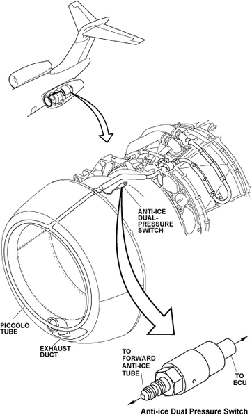
The high pressure (HP) compressor of each engine supplies their related nacelle thermal anti-ice system. The hot air from the engine is supplied to the nacelle inlet through a piccolo tube. The anti-ice valve controls the pressure in the system.The anti-ice dual pressure switch monitors the pressure in the system. The used air is released overboard through the exhaust duct.
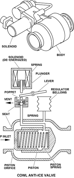
Cowl Anti-Ice Valve
There is one anti-ice valve installed on each engine.
The forward and aft anti-ice tubes hold the anti-ice valve. A tab in the forward flange of the valve aligns correctly the valve and the forward anti-ice tube.
The anti-ice valve is electrically operated and pneumatically controlled. With the solenoid energized, the anti-ice valve is closed. Circuit breakers CB1-E11 and CB2-E11 supply 28 VDC to the anti-ice valve solenoid.
The valve has a push-type solenoid for the shut-off function. When the solenoid is energized, the solenoid plunger pushes on the regulator lever that pushes on the control section poppet. That causes the poppet to seal against the seat. This closes the control section airflow and causes the valve to close.
When the valve receives a command input to close at higher inlet pressure, the regulator bellows moves the lever which puts the control section poppet near the seat. When the solenoid energizes, this causes the plunger to move the regulator lever and control section poppet to the closed position.
At any inlet pressure, the regulator bellows does not provide any opposing force to the shut-off function.
When the solenoid is de-energized, the return spring in the solenoid causes the solenoid plunger to move away from the regulator lever. Pneumatic pressure in the valve piston causes the control section poppet to move up or down from the seat. It will only move to the regulator lever. A small spring helps to move the poppet away from the seat at lower inlet pressures.
With the solenoid de-energized, the regulator bellows sets its plunger in relation to the pneumatic pressure downstream of the valve piston. This downstream pressure is sensed by means of a tube assembly that is part of the valve. The bellows plunger pushes against the regulator lever which, in turn, sets the control section poppet at the appropriate distance from the poppet seat, which lets the valve adjust the downstream pressure.

Anti-Ice Dual Pressure Switch
The anti-ice dual pressure switch connects to the forward anti-ice tube. A bracket, attached to the engine casing, holds the pressure switch. An electrical connection connects the pressure switch to the ECU.
Anti-Ice Tubes
The aft anti-ice tube is connected to the HP bleed-air duct and the anti-ice valve by V-band couplings. A P-clip and a bracket, attached to the engine casing, hold the aft anti-ice tube. A link assembly, which attaches to the aft anti-ice tube, keeps it at the correct distance from the engine casing. Two insulation sleeves with spring fasteners are installed around the aft anti-ice tube to prevent damage to the adjacent components.
The forward anti-ice tube is connected to the anti-ice valve and the piccolo tube by V-band couplings. The P-clip and a bracket, attached to the engine casing, hold the forward anti-ice tube. A notch in the aft flange of the tube correctly aligns the anti-ice valve to the forward anti-ice tube. Integral insulation is installed around the forward anti-ice tube to prevent damage to the adjacent components.


Piccolo Tube
The piccolo tube is an annular tube attached to the forward bulkhead of the nacelle air intake. An integral feeder pipe goes through the forward and aft bulkheads of the nacelle air intake. It is connected to the forward anti-ice tube by a V-band coupling.
The piccolo tube distributes the hot air evenly around the inside of the nose lip. The exhaust duct in the bottom of the air intake lets the used air out of the nose lip.

12/29/15
System Interface
The engine nacelle anti-ice system interfaces with the systems that follow:
- Ice Detection System
- Nacelle Inlet
- Engine Anti-Icing
- The Full-Authority Digital Engine Control System (FADEC)
System Operation
When ice is sensed, by the ice detection system, a ICE DETECTED caution message is shown on the EICAS display and an ICE flag is displayed on the primary flight display (PFD). The flight crew must push the L (R) ENG and the WING pushbutton annunciators (PBAs) on the anti-ice control panel. If the wing and engine anti-ice systems are set to ON, the ICE DETECTED caution message changes to an advisory message on the EICAS display and the ICE flag is removed from the PFD.
Bleed air comes from the engine HP bleed port. Hot bleed air goes through anti-ice tubes to an annular piccolo tube in the nacelle air intake lip. The anti-ice valve pneumatically controls the bleed air pressure in the nacelle anti-ice system at a nominal 45 psig (310.26 kPa).
The anti-ice dual pressure-switch monitors the pressure in the anti-ice tube. The electronic control unit (ECU) of the FADEC system will send the L (R) ENG ANTI-ICE FAIL caution message when the engine anti-ice is set to ON and the pressure decreases to less than 9.50 psig (65.50 kPa) in the system. The message will go out of view when the pressure increases above 13 psig (89.63 kPa).
The L (R) ENG A/ICE FAIL ON advisory message will show when one of the conditions that follow occurs:
- The FADEC system senses that the cowl anti-ice valve becomes defective, or
- The FADEC system senses that the engine inlet temperature (Tt2) sensor becomes defective.
Note:
If one of the components given above becomes defective, the nacelle anti-ice system will operate without a command.
The ENG ANTI-ICE ON status message will show when both the L and R engine anti-ice are set ON.
The L (R) ENG ANTI-ICE ON status message will show when the L or the R engine anti-ice it set ON.
The EICAS messages that follow are related to the engine nacelle anti-ice system:
| EICAS MESSAGE(S) | LEVEL (COLOR) |
| L ENG ANTI-ICE FAIL | CAUTION (amber) |
| R ENG ANTI-ICE FAIL | CAUTION (amber) |
| ICE DETECTED | CAUTION (amber) |
| L ENG A/ICE FAIL ON | ADVISORY (cyan) |
| R ENG A/ICE FAIL ON | ADVISORY (cyan) |
| ICE DETECTED | ADVISORY (cyan) |
| ENG ANTI-ICE ON | STATUS (white) |
| L ENG ANTI-ICE ON | STATUS (white) |
| R ENG ANTI-ICE ON | STATUS (white) |
The status of the cowl anti-ice valves is shown on the anti-ice synoptic page. The cowl anti-ice valves are shown with a fix contour and a flow line that moves (valve opened/valve closed). The contour color is white and the flow line color is usually the same as the one of the adjacent flow lines. The ducts are shown as flow lines. The flow lines color can be one of those that follow:
- Red to show an unserviceable status
- Amber to show a caution
- White to show a usual status with no airflow
- Green to show a usual status with airflow
- Magenta to show invalid or unknown status.


10/16/20
Component Location Index
| Component Location Index | |||
|---|---|---|---|
| IDENT | DESCRIPTION | LOCATION | IPC REF |
| - | LEFT ENGINE COWL ANTI-ICE VALVE | PANEL(S) 432BT, ZONE(S) 430 | 30-21-00 |
| - | RIGHT ENGINE COWL ANTI-ICE VALVE | PANEL(S) 422BT, ZONE(S) 440 | 30-21-00 |
| - | LEF T ENGINE AFT ANTI-ICE TUBE, | PANEL(S) 432BT, ZONE(S) 430 | 30-21-00 |
| - | RIGHT ENGINE AFT ANTI-ICE TUBE | PANEL(S) 442BT, ZONE(S) 440 | 30-21-00 |
| - | LEFT ENGINE FORWARD ANTI-ICE TUBE | PANEL(S) 432BT, ZONE(S) 430 | 30-21-00 |
| - | RIGHT E NGINE FORWARDANTI-ICE TUBE | PANEL(S) 442BT, ZONE(S) 440 | 30-21-00 |
| - | LEFT ENGINE ANTI-ICE DUAL PRESSURE SWITCH |
PANEL(S) 432BT, ZONE(S) 430 | 30-21-03 |
| - | RIGHT ENGINE ANTI-ICE DUAL PRESSURE SWITCH |
PANEL(S) 442BT, ZONE(S) 440 | 30-21-03 |