


01/06/16
Overview
This section contains a description of the instrument and control panels installed in the flight compartment. It includes the panels that can be removed and the panels that cannot be removed. The panels supply the mounting bases for components such as display units, instruments, controls, levers/handles, switches, switch/lights, circuit breakers, fuses, and other accessories.

12/31/21
Main Instrument Panel
The main instrument panel is installed in the forward zone of the flight compartment. It includes three different areas (center, left end, and right end areas). The main instrument panel supplies the mounting base for the adaptive display units and different control panels and instruments. The main instrument panel includes the components that follow:
- Main Instrument Panel
- Pilot's Side Instrument Panel
- Copilot's Side Instrument Panel
Main Instrument Panel
The main instrument panel (in the center area) supplies the mounting base for the four primary adaptive display units and for other instruments and controls.
On the left side, the main instrument panel includes the components that follow:
- One primary flight display (PFD)
- One multi-function display (MFD)
In the center, the main instrument panel includes the components that follow:
- One integrated standby instrument (ISI)
- One clock
- One TAWS/LANDING GEAR control-panel for the terrain-avoidance warning system (TAWS) and the landing gear system
On the right side, the main instrument panel includes the components that follow:
- One primary flight display (PFD)
- One multi-function display (MFD)
Pilot's Side Instrument Panel
On A/C Pre SB 350-53-002
The pilot's side instrument panel supplies the mounting base for the components that follow:
- One BARO utility panel that includes rudder control, and air data systems
- One AUDIO CONTROL panel
- One air vent
On A/C Post SB 350-53-002
The pilot's side instrument panel supplies the mounting base for the components that follow:
- One BARO utility panel that includes rudder control, and air data systems
- One AUDIO CONTROL panel
- One air vent
- Switch guard
Copilot's Side Instrument Panel
On A/C Pre SB 350-53-002
The copilot's side instrument panel supplies the mounting base for the components that follow:
- One BARO utility panel that includes rudder control, and air data systems
- One AUDIO CONTROL panel
- One air vent
On A/C Post SB 350-53-002
The copilot's side instrument panel supplies the mounting base for the components that follow:
- One BARO utility panel that includes rudder control, and air data systems
- One AUDIO CONTROL panel
- One air vent
- Switch guard


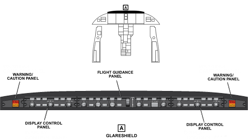
Glareshield
The glareshield helps to prevent sun glare on the instrument panels. It is also used to attach different control panels.
The glareshield panel is installed below the windshield and above the main instrument panel. It supplies the mounting base for the components that follow:
- One flight guidance panel (FGP) in the center area
- Two display control panels (DCPs) (one for the pilot and the other for the copilot)
- Two WARNING/CAUTION panels (one for the pilot and the other for the copilot)
The flight guidance panel contains the controls (buttons, pushbuttons, rotary switches, command wheel) that supply the primary interface with the automatic flight-control system (AFCS).
The display control panels are the primary interfaces to do the selection and control of the different formats, data, and configurations on the displays.
The WARNING/CAUTION panels have pushbutton annunciators (PBA) that are used to show system malfunction to the flight crew.


03/30/22
Center Pedestal
The center pedestal is the center console installed on the floor between the pilot' s and copilot's seats. It contains control display units, control panels, handles, and levers.
The center pedestal has a forward area and an aft area. The forward area has nine different housings and the aft area has 19 different housings.
The forward area of the center pedestal supplies the mounting base for the components that follow
- One FUEL control panel
- One control panel for the air conditioning and bleed air system (AIR COND/BLEED control-panel)
- One PRESSURIZATION control panel
- One copilot control display unit (CDU) for the flight management system (FMS) (the pilot CDU is installed with the dual CDU installation)
- One ANTI-ICE control panel
- One ELECTRICAL control panel
- Two multi-function display (MFD) controllers (cursor control panels [CCPs])
The aft area of the center pedestal supplies the mounting base for the components that follow:
- One flight-spoiler control panel
- One throttle quadrant (which includes the L and R ENGINE RUN controls)
- One HYDRAULIC control panel
- One FLAP lever
- One control for the pitch disconnect function (PITCH DISC handle)
- One control panel for the ground (GND) spoilers and roll spoilers (GND/ROLL SPOILERS control-panel)
- One TRIM/STALL control-panel
- One control for the parking and emergency brake functions (PARK/EMER BRAKE handle)
- One reversion select panel (RSP)
- One SYSTEMS TEST control-panel
- One ENGINE control panel (which includes the fire extinguishing controls for the engines and APU)
- One emergency locator transmitter (ELT) panel
- One APU control panel
- One landing-gear manual-release handle
- One COCKPIT VOICE RECORDER panel
- One control panel for the passenger oxygen system (OXYGEN control-panel)
- One CABIN control-panel (for the control of the cabin power and lights)
- One cover panel that can be replaced by the possible future option


Side Consoles
There are two side consoles installed in the flight compartment. They supply storage areas and contain different controls, components, and accessories.
The side consoles include the components that follow:
- Pilot Side Console
- Copilot Side Console.
The pilot side console is found on the outboard side of the pilots' seat. It supplies the mounting base for the components/accessories that follow:
- One NOSEWHEEL STEERING handwheel
- One cup holder
- One COCKPIT LIGHTS control panel
- One headset jack panel (with headphone (HDPH) and microphone (MIC) audio jacks)
- One microphone (MIC) jack panel
- One storage compartment.
The copilot side console is found on the outboard side of the copilots' seat. It supplies the mounting base for the components/accessories that follow:
- One cup holder
- One COCKPIT LIGHTS control panel
- One headset jack panel (with headphone (HDPH) and microphone (MIC) audio jacks)
- One microphone (MIC) jack panel
- One storage compartment

06/28/22
Cockpit Circuit-Breakers Panel (CCBP)
wo cockpit circuit-breaker panels (CCBPs) supply electrical power to all the essential and primary loads which can be closed mechanically (reset) from the flight compartment if they open. The CCBPs are located in the flight compartment.
The circuit breakers panels are used:
- To ensure the distribution of the 28 VDC electrical power to flight essential/very important services
- To give protection to the distribution wiring against unusual current or short circuit current
There is a left CCBP found on the bulkhead behind the pilot seat. There is a right CCBP found on the bulkhead behind the copilot seat. They are installed on the equipment racks with six quick-release fasteners found at the top and the bottom of the CCBP.
A hinge lets the panel be opened 70 degrees max for maintenance access. It opens outboard. There is a stopper that prevents the panel to open more than 70 degrees. There is also a guard assembly on the front of the panel for protection against contact with the pilot and copilot seats. Each CCBP has 75 circuit breakers. There are two studs on the rear of the CCBP where the power is supplied to the panel. There are three connectors on the side of the panel for the outputs from the CCBP.
The CCBPs are supplied by the distribution busses located in the DC power center (DCPC) through the secondary power center (SPC).
The lighting of the legend of the CCBP is supplied by the integral lighting controller. The lighting is controlled by the CB PANELS rotary button on the COCKPIT LIGHTS control-panel.
The identification, the label and the related system of each circuit breaker are given in the tables that follow:
For the left CCBP,
|
CB IDENT |
CB LABEL |
SYSTEM |
|---|---|---|
|
CB1-A1 |
AVIONICS NAVIGATION NAV 1 |
VHF Navigation System |
|
CB1-A2 |
AVIONICS NAVIGATION DME 1 |
Distance Measuring Equipment (DME) System |
|
CB1-A3 |
AVIONICS NAVIGATION GPS 1 |
Global Positioning System (GPS) |
|
CB1-A4 |
AVIONICS NAVIGATION CDU 1 |
Flight Management System |
|
CB1-A5 |
AVIONICS NAVIGATION XPDR 1 |
Air Traffic Control (ATC) Transponder System |
|
CB1-A6 |
AVIONICS NAVIGATION TCAS |
Traffic Alert and Collision-Avoidance System (TCAS) |
|
CB1-A7 |
AVIONICS NAVIGATION RAD ALT |
Radio Altimeter System |
|
CB1-A8 |
AVIONICS NAVIGATION WX |
Weather Radar System |
|
CB1-A9 |
FUEL L PUMP CTRL |
Fuel Distribution System |
|
CB1-A10 |
FUEL L PUMP PWR |
Fuel Distribution System |
|
CB1-A11 |
FIRE DET CH A |
Fire-Detection-And-Extinguishing (FIREX) System |
|
CB1-A12 |
ENGINE FADEC R CH A |
Full-Authority Digital Engine-Control (FADEC) System |
|
CB1-A13 |
ENGINE FADEC L CH A |
Full-Authority Digital Engine-Control (FADEC) System |
|
CB1-A14 |
ENGINE L TR CTRL 1 |
Thrust Reverser |
|
CB1-A15 |
ENGINE L TR CTRL 2 |
Thrust Reverser |
|
CB1-B1 |
AVIONICS COMMUNICATION L AUDIO PWR 1 |
Audio Integrating System |
|
CB1-B2 |
AVIONICS COMMUNICATION COM 1 |
VHF Communication System |
|
CB1-B3 |
AVIONICS COMMUNICATION HF 1 |
HF Communication System |
|
CB1-B4 |
AVIONICS COMMUNICATION RIU 1B/AURAL |
Audio Integrating System |
|
CB1-B5 |
AVIONICS COMMUNICATION RIU 1A |
Audio Integrating System |
|
CB1-B6 |
AVIONICS AUTOFLIGHT L IAPS |
Integrated-Avionics Processor System (IAPS) |
|
CB1-B7 |
AVIONICS AUTOFLIGHT L FGP/SERVOS |
Automatic Flight-Control System (AFCS) |
|
CB1-B8 |
APU PRI |
APU System |
|
CB1-B9 |
FLIGHT CONTROLS SPOILER CTRL 1 |
Spoilers |
|
CB1-B10 |
FLIGHT CONTROLS STALL L PWR |
Stall Protection System (SPS) |
|
CB1-B11 |
FLIGHT CONTROLS STALL L SHKR |
Stall Protection System (SPS) |
|
CB1-B12 |
FLIGHT CONTROLS STALL PUSHER |
Stall Protection System (SPS) |
|
CB1-B13 |
FLAP L IND |
Flap System |
|
CB1-B14 |
FLAP CTRL |
Flap System |
|
CB1-B15 |
PRI STAB TRIM/RUD LIM |
Pitch Trim System |
|
CB1-C1 |
AVIONICS INDICATING/RECORDING DISPLAYS AIR DATA 1 |
Air Data System |
|
CB1-C2 |
AVIONICS INDICATING/RECORDING DISPLAYS ATT HDG 1 |
Attitude and Heading Reference System |
|
CB1-C3 |
AVIONICS INDICATING/RECORDING DISPLAYS L PFD |
Electronic Flight-Instrument System (EFIS) |
|
CB1-C4 |
AVIONICS INDICATING/RECORDING DISPLAYS L DCP |
Electronic Flight-Instrument System (EFIS) |
|
CB1-C5 |
AVIONICS INDICATING/RECORDING DISPLAYS L MFD |
Electronic Flight-Instrument System (EFIS) |
|
CB1-C6 |
L FILE SERVER |
Integrated Flight Information System (IFIS) |
|
CB1-C7 |
XM WEATHER (A/C Post SB 350-46-002 or A/C Post SB 350-46-006) |
Integrated Flight Information System (IFIS) |
| CB1-C8 | HUD (A/C POST SB 995GC02Y-24-009) | Head-Up-Display (HUD) (Option) |
|
CB1-C9 |
HYDRAULIC L IND |
Hydraulic Power Indicating |
|
CB1-C10 |
HYDRAULIC L SOV |
Left Hydraulic System |
|
CB1-C11 |
HYDRAULIC R DC PUMP |
Right Hydraulic System |
|
CB1-C12 |
LDG GEAR NWS PWR 1 |
Nosewheel-Steering Control System |
|
CB1-C13 |
LDG GEAR WOW A/RET/EXT |
Position Indication System |
|
CB1-C14 |
LDG GEAR WOW B |
Position Indication System |
|
CB1-C15 |
LDG GEAR INBD BRAKES |
Brake Control System |
|
CB1-D1 |
AVIONICS INDICATING/RECORDING DCU A |
Engine Indicating and Crew Alerting System (EICAS) |
|
CB1-D2 |
AVIONICS INDICATING/RECORDING RDC A |
Engine Indicating and Crew Alerting System (EICAS) |
|
CB1-D3 |
AVIONICS INDICATING/RECORDING ANNUNCIATOR CTRL 1 |
Warning/Caution Control System |
|
CB1-D4 |
AVIONICS INDICATING/RECORDING ANNUNCIATOR L PWR 1 |
Warning/Caution Control System |
|
CB1-D5 |
AVIONICS INDICATING/RECORDING ANNUNCIATOR R PWR 2 |
Warning/Caution Control System |
|
CB1-D6 |
AVIONICS INDICATING/RECORDING CVR (A/C 20501 to 20739 Pre SB 350-31-004) |
Voice Recorder System |
| CB1-D6 | AVIONICS INDICATING/RECORDING FDR (A/C 20740 and Subs and A/C 20501 to 20739 Post SB 350-31-004) |
Flight-Data Recording System (option) |
| CB1-D7 | EVS SENSOR(A/C POST SB 995GC02Y-24-009) | Enhanced Vision System (EVS) (option) |
| CB1-D8 | EVS HEATER (A/C POST SB 995GC02Y-24-009) | Enhanced Vision System (EVS) Heater (option) |
|
CB1-D9 |
HYDRAULIC AUX IND |
Hydraulic Power Indicating |
|
CB1-D10 |
HYDRAULIC AUX DC PUMP |
Auxiliary Hydraulic System |
|
CB1-D13 |
ENVIRONMENTAL ALT LIM/ECS X VLV PWR 2 |
Air Conditioning System |
|
CB1-D14 |
ENVIRONMENTAL PRESS 1/PACK |
Air Conditioning System |
|
CB1-D15 |
ENVIRONMENTAL L BLEED VALVES |
Air Conditioning System |
|
CB1-E1 |
ANTI-ICE L PROBE CTRL |
Air Data Probes and Sensors |
|
CB1-E2 |
ANTI-ICE L PITOT |
Air Data Probes and Sensors |
|
CB1-E3 |
ANTI-ICE L STBY STATIC |
Air Data Probes and Sensors |
|
CB1-E4 |
ANTI-ICE TAT |
Air Data Probes and Sensors |
|
CB1-E5 |
ANTI-ICE L AOA VANE |
Air Data Probes and Sensors |
|
CB1-E6 |
ANTI-ICE L AOA CASE |
Air Data Probes and Sensors |
|
CB1-E7 |
ANTI-ICE L ICE DET |
Ice Detection System |
|
CB1-E8 |
ANTI-ICE L WINDSHIELD CTRL |
Windshield and Side-Window Anti-ice |
|
CB1-E9 |
ANTI-ICE L WINDSHIELD PWR |
Windshield and Side-Window Anti-ice |
|
CB1-E10 |
ANTI-ICE L WING/BLD LK |
Wing Anti-Ice System |
|
CB1-E11 |
ANTI-ICE L ENG |
Engine Nacelle Anti-Ice |
For the right CCBP,
|
CB IDENT |
CB LABEL |
SYSTEM |
|---|---|---|
|
CB2-A1 |
AVIONICS NAVIGATION NAV 2 |
VHF Navigation System |
|
CB2-A2 |
AVIONICS NAVIGATION DME 2 |
Distance Measuring Equipment (DME) System |
|
CB2-A3 |
AVIONICS NAVIGATION GPS 2 |
Global Positioning System (GPS) |
|
CB2-A4 |
AVIONICS NAVIGATION CDU 2 |
Flight Management System |
|
CB2-A5 |
AVIONICS NAVIGATION XPDR 2 |
Air Traffic Control (ATC) Transponder System |
|
CB2-A6 |
AVIONICS NAVIGATION TAWS |
Terrain-Avoidance Warning System (TAWS) |
|
CB2-A7 |
SVS |
Synthetic Vision System |
| CB2-A8 | AUTO THROTTLE A/C 20875 and Subs |
Auto Throttle System |
|
CB2-A9 |
FUEL R PUMP PWR |
Fuel Distribution System |
|
CB2-A10 |
FUEL R PUMP CTRL |
Fuel Distribution System |
|
CB2-A11 |
FIRE DET CH B |
Fire-Detection-And-Extinguishing (FIREX) System |
|
CB2-A12 |
ENGINE FADEC R CH B |
Full-Authority Digital Engine-Control (FADEC) System |
|
CB2-A13 |
ENGINE FADEC L CH B |
Full-Authority Digital Engine-Control (FADEC) System |
|
CB2-A14 |
ENGINE R TR CTRL 1 |
Thrust Reverser |
|
CB2-A15 |
ENGINE R TR CTRL 2 |
Thrust Reverser |
|
CB2-B1 |
AVIONICS COMMUNICATION R AUDIO PWR 1 |
Audio Integrating System |
|
CB2-B2 |
AVIONICS COMMUNICATION COM 2 |
VHF Communication System |
|
CB2-B3 |
AVIONICS COMMUNICATION HF 2 |
HF Communication System (option) |
|
CB2-B4 |
AVIONICS COMMUNICATION RIU 2A |
Audio Integrating System |
|
CB2-B5 |
AVIONICS COMMUNICATION RIU 2B/AURAL |
Audio Integrating System |
|
CB2-B6 |
AVIONICS AUTOFLIGHT R IAPS |
Integrated-Avionics Processor System (IAPS) |
|
CB2-B7 |
AVIONICS AUTOFLIGHT R FGP/SERVOS |
Automatic Flight-Control System (AFCS) |
|
CB2-B8 |
APU SEC |
APU System |
|
CB2-B9 |
FLIGHT CONTROLS SPOILER CTRL 2 |
Spoilers |
|
CB2-B10 |
FLIGHT CONTROLS STALL R PWR |
Stall Protection System (SPS) |
|
CB2-B11 |
FLIGHT CONTROLS STALL R SHKR |
Stall Protection System (SPS) |
|
CB2-B12 |
FLIGHT CONTROLS FLAP R IND/CTRL |
Flap System |
|
CB2-B13 |
FLIGHT CONTROLS SEC STAB TRIM/RUD LIM |
Pitch Trim System |
|
CB2-B14 |
FLIGHT CONTROLS RUD TRIM |
Rudder Control System |
|
CB2-B15 |
FLIGHT CONTROLS AIL TRIM |
Aileron Control System |
|
CB2-C1 |
AVIONICS INDICATING/RECORDING DISPLAYS AIR DATA 2 |
Air Data System |
|
CB2-C2 |
AVIONICS INDICATING/RECORDING DISPLAYS ATT HDG 2 AVIONICS INDICATING/RECORDING DISPLAYS IRU 2 |
Attitude and Heading Reference System |
|
CB2-C3 |
AVIONICS INDICATING/RECORDING DISPLAYS R PFD |
Electronic Flight-Instrument System (EFIS) |
|
CB2-C4 |
AVIONICS INDICATING/RECORDING DISPLAYS R DCP |
Electronic Flight-Instrument System (EFIS) |
|
CB2-C5 |
AVIONICS INDICATING/RECORDING DISPLAYS R MFD |
Electronic Flight-Instrument System (EFIS) |
|
CB2-C6 |
AVIONICS INDICATING/RECORDING DISPLAYS STBY INST/BATT |
Standby Air-Data System |
|
CB2-C7 |
STBY INST BATT TEST |
Standby Air-Data System |
|
CB2-C8 |
HYDRAULIC R IND |
Hydraulic Power Indicating |
|
CB2-C9 |
HYDRAULIC R SOV |
Right Hydraulic System |
|
CB2-C10 |
HYDRAULIC PTU |
Right Hydraulic System |
|
CB2-C11 |
HYDRAULIC L DC PUMP |
Left Hydraulic System |
|
CB2-C12 |
LDG GEAR NWS PWR 2 |
Nosewheel-Steering Control System |
|
CB2-C13 |
LDG GEAR WOW B/EXT |
Position Indication System |
|
CB2-C14 |
LDG GEAR WOW A/RET |
Position Indication System |
|
CB2-C15 |
LDG GEAR OUTBD BRAKES |
Brake Control System |
|
CB2-D1 |
AVIONICS INDICATING/RECORDING DCU B |
Engine Indicating and Crew Alerting System (EICAS) |
|
CB2-D2 |
AVIONICS INDICATING/RECORDING RDC B |
Engine Indicating and Crew Alerting System (EICAS) |
|
CB2-D3 |
AVIONICS INDICATING/RECORDING ANNUNCIATOR CTRL 2 |
Warning/Caution Control System |
|
CB2-D4 |
AVIONICS INDICATING/RECORDING ANNUNCIATOR R PWR 1 |
Warning/Caution Control System |
|
CB2-D5 |
AVIONICS INDICATING/RECORDING ANNUNCIATOR L PWR 2 |
Warning/Caution Control System |
|
CB2-D6 |
R FILE SERVER |
Integrated Flight Information System (IFIS) |
| CB2-D7 | AVIONICS INDICATING/RECORDING FDR (A/C 20501 to 20739 Pre SB 350-31-004) |
Flight-Data Recording System (option) |
| CB2-D7 | AVIONICS INDICATING/RECORDING CVR (A/C 20740 and Subs and A/C 20501 to 20739 Post SB 350-31-004) |
Voice Recorder System |
|
CB2-D11 |
ENVIRONMENTAL CARGO HEATER |
Air Conditioning System |
|
CB2-D12 |
ENVIRONMENTAL X BLEED VALVE |
Cabin-Pressure Control System |
|
CB2-D13 |
ENVIRONMENTAL ALT LIM/ECS X VLV PWR 1 |
Air Conditioning System |
|
CB2-D14 |
ENVIRONMENTAL PRESS 2/TRIM |
Air Conditioning System |
|
CB2-D15 |
ENVIRONMENTAL R BLEED VALVES |
Air Conditioning System |
|
CB2-E1 |
ANTI-ICE R PROBE CTRL |
Air Data Probes and Sensors |
|
CB2-E2 |
ANTI-ICE R PITOT |
Air Data Probes and Sensors |
|
CB2-E3 |
ANTI-ICE STBY PITOT |
Air Data Probes and Sensors |
|
CB2-E4 |
ANTI-ICE R STBY STATIC |
Air Data Probes and Sensors |
|
CB2-E5 |
ANTI-ICE R AOA VANE |
Air Data Probes and Sensors |
|
CB2-E6 |
ANTI-ICE R AOA CASE |
Air Data Probes and Sensors |
|
CB2-E7 |
ANTI-ICE R ICE DET |
Ice Detection System |
|
CB2-E8 |
ANTI-ICE R WINDSHIELD CTRL |
Windshield and Side-Window Anti-ice |
|
CB2-E9 |
ANTI-ICE R WINDSHIELD PWR |
Windshield and Side-Window Anti-ice |
|
CB2-E10 |
ANTI-ICE R WING/BLD LK |
Wing Anti-Ice System |
|
CB2-E11 |
ANTI-ICE R ENG |
Engine Nacelle Anti-Ice |
|
CB2-E14 |
LIGHTS DOME |
Miscellaneous Lighting |
|
CB2-E15 |
LIGHTS EMER |
Emergency Lighting System |
The power inputs are connected on the CCBP through two studs. The name, the designation and the connection of the studs are given in the table that follows:
|
NAME |
DESIGNATION |
CONNECTION |
|---|---|---|
|
CBP1 Stud T1 |
LCBP Stud T1 |
L MAIN BUS from left SPC |
|
CBP1 Stud T2 |
LCBP Stud T2 |
L ESS BUS from left SPC |
|
CBP2 Stud T1 |
RCBP Stud T1 |
R MAIN BUS from right SPC |
|
CBP2 Stud T2 |
RCBP Stud T2 |
R ESS BUS from right SPC |
The output is done through three connectors with different dimension. The name, designation and connection of the connectors are given in the table that follows:
|
NAME |
DESIGNATION |
CONNECTION |
|---|---|---|
|
CBP1 J1 |
LCBP connector P1 |
L BATT BUS / L ESS BUS |
|
CBP1 J2 |
LCBP connector P2 |
L ESS BUS |
|
CBP1 J3 |
LCBP connector P3 |
L MAIN BUS |
|
CBP2 J1 |
RCBP connector P1 |
R MAIN BUS |
|
CBP2 J2 |
RCBP connector P2 |
R MAIN BUS |
|
CBP2 J3 |
RCBP connector P3 |
R BATT BUS / R ESS BUS |


01/07/16
System Interface
The CCBP has interfaces with the systems/components that follow:
- Panel Integral Lighting
- DC Power Center (DCPC)
- Secondary Power Center (SPC)
10/30/20
Component Location Index
| Component Location Index | |||
|---|---|---|---|
| IDENT | DESCRIPTION | LOCATION | IPC REF |
| - | MAIN INSTRUMENT PANEL | ZONE(S) 211 | 31-11-01 |
| - | GLARESHIELD PANEL | ZONE(S) 211 | 31-13-01 |
| - | CENTER PEDESTAL | ZONE(S) 211 | 31-14-01 |
| - | PILOT SIDE CONSOLE | ZONE(S) 211 | 31-16-03 |
| - | COPILOT SIDE CONSOLE | ZONE(S) 212 | 31-16-05 |
| CBP1 | COCKPIT CIRCUIT-BREAKER PANEL (CCBP) (LH) | ZONE(S) 211 | 31-17-01 |
| CBP2 | COCKPIT CIRCUIT-BREAKER PANEL (CCBP) (RH) | ZONE(S) 212 | 31-17-01 |