


Overview
Note:
The optional Flight Date Recorder system is installed via SB350-31-001.
The flight data recorder (FDR) monitors real time flight data and puts it in a crash survivable memory unit (CSMU) where it can be retrieved for analysis.
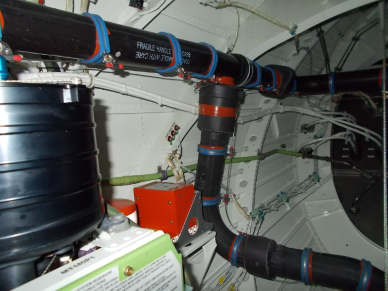
The FDR is an LRU the aft equipment compartment. It has an underwater locating mmm device (ULD radio beacon) to help find the FDR after impact in water. The flight data recording system records different aircraft flight parameters that occurred in the last 25 hours.
The primary components of the flight data recording system are a solid state FDR and a triaxial accelerometer. The FDR receives aircraft data from the data concentrator unit (DCU) and stores it in a solid state CSMU. The recorded flight data can be read with ground support equipment (GSE) through a connector at the front. The FDR also has a connector at the rear for the aircraft interface. The FDR impact switch is a sealed device with two contact terminals and a reset switch that prevents memory erasure if the aircraft goes into a fast 2G deceleration in the forward and down direction, or after impact. The impact switch opens and removes power to the FDR. The FDR impact switch is in the aft equipment compartment.
The triaxial accelerometer is a sealed instrument mounted under the floor, that contains three separate seismic sensors that measure acceleration on three axes (vertical, lateral, and longitudinal). It measures acceleration near the center of gravity of the aircraft and supplies the information to the DCUs to be formatted for the FDR.
An event switch, located on the center pedestal engine control panel, is used by the flight crew to add a data flag to an event that is being recorded in the FDR memory. The switch is pressed for two seconds as the event occurs.
A built-in test operation detects a fault with the recorder within five seconds after power is applied. In this case, an FDR FAIL or FDR FAULT message appears and the fault information is stored in NVM fault history log.
09/05/18
Flight Data Recorder
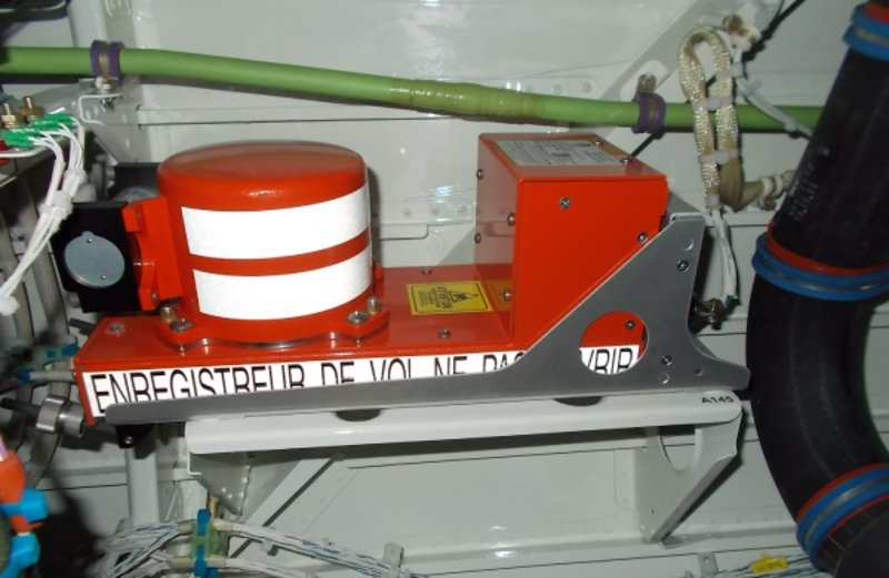
The FDR is a line replaceable unit (LRU) located in the aft equipment compartment. This LRU is installed in the FDR tray at FS798.00, on the RHS. The FDR is specially made to be resistant to shocks and heat related to an aircraft crash. The color of the FDR is International Orange and has stripes that give reflection, as per the National Transportation Safety Board (NTSB).
The FDR monitors real-time flight data and puts it in a crash-survivable memory unit (CSMU). The data can be read from the FDR for analysis.
An underwater locating device (ULD) is installed in front of the recorder. The ULD is a radio beacon that helps to find the FDR location after a crash in water.
The FDR has a connector at the rear, for the aircraft interface. Also it has a connector at the front, for the GSE interface.
On A/C 20501 to 20739 Pre SB 350-31-004, The FDR system operates on 28 VDC power supplied by the R ESS BUS.
On A/C 20740 and Subs and ON A/C 20501 to 20739 Post SB 350-31-004, the FDR system operates on 28 VDC power supplied by the L ESS BUS.
As a system, the FDR function is made with the internal components that follow:
Aircraft Interface Unit
The aircraft interface unit supplies the signal conditioning, input protection and primary power supply. Also, it supplies FDR status to the DCU.
Acquisition Processor
The acquisition processor unit is an internal component of the FDR assembly. It supplies the logic power supplies, microprocessors, interface to the CSMU and interface to the GSE. This component transfers recorded data from the CSMU to the GSE.
Crash Survivable Memory Unit (CSMU)
The CSMU is a solid-state, nonvolatile, high-capacity storage device that is contained in a strong protective housing. This gives a physical protection from the mechanical effects of a crash impact, deep sea pressure and also a thermal protection from effects of a fire that can occur. The CSMU is found on the FDR assembly.

Flight Data Recorder Tray
The flight data recorder (FDR) tray has a connector at the rear that connects to the FDR aircraft interface connector. The FDR attaches to the tray with two hold-down clamps.

Triaxial Accelerometer
The triaxial accelerometer has a hermetic seal and contains three seismic sensors to measure acceleration along each of the three axes. The triaxial accelerometer is an instrument that measures vertical (up/down), longitudinal (forward/aft) and lateral (right/left) acceleration. The accelerometer outputs are sent to the DCU before they are supplied to the FDR.
The triaxial accelerometer is installed in the main landing gear (MLG) wheel well near the aircraft center line at FS589.53.

Flight Data Recorder Underwater Locating Device
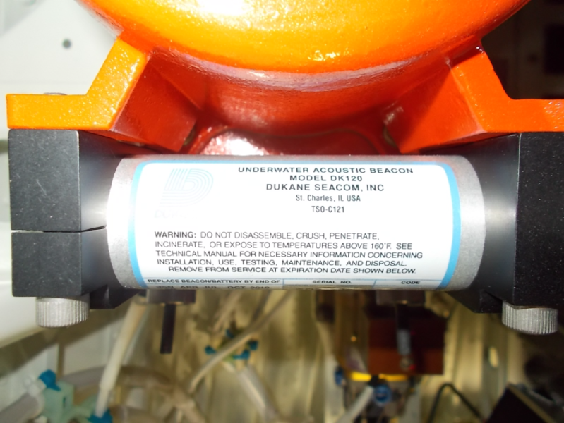
The FDR has an ULD to help for the location of the aircraft loss in water. The ULD is an LRU attached to the CSMU on the front of the FDR with two mounting brackets and four screws. This makes it easy to read the battery replacement date and to remove or replace the beacon.
The ULD contains an acoustic beacon, a battery, and a water switch. It transmits a signal when the water switch closes. The battery is also a LRU. It must be replaced before the date shown on the label on the ULD is expired.
When the water switch is wet, the battery supplies power to the oscillator which causes the electromagnetic transducer to send out a 37.5 ± 1 kHz signal. The signal is transmitted for a minimum of 30 days at a range of 2,000 to 4,000 yd (1,828.80 to 3,657.60 m). The ULD is resistant to sea depths of 20,000 ft (6,096.00 m).

08/23/16
Flight Data Recorder Impact Switch
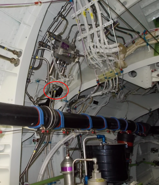
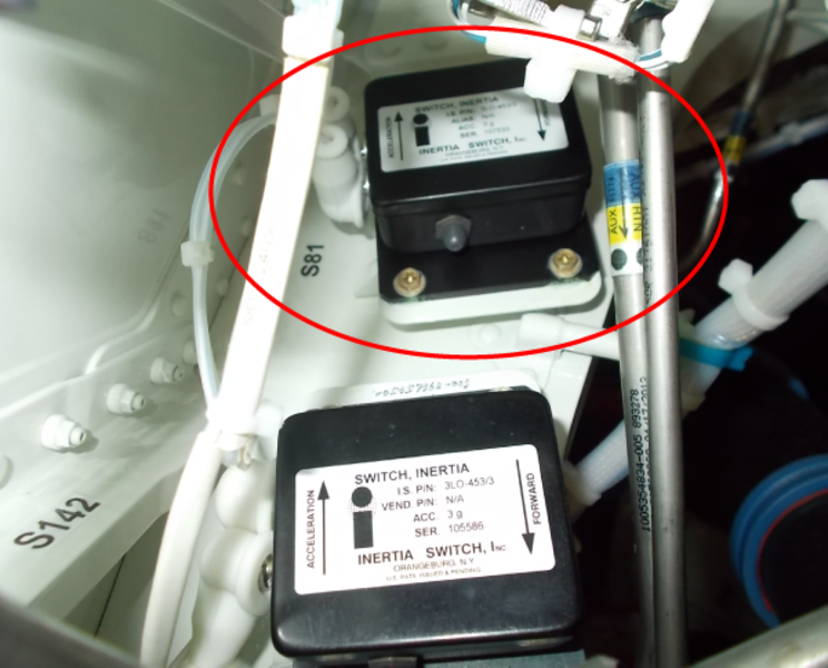
The FDR impact switch (S81) is an inertia type switch installed in the aft equipment compartment at FS784.00 (Post SB350-31-001).
The FDR impact switch is a sealed device that has two connectors and a reset pushbutton. This switch controls the power supply to the FDR. In usual conditions, the switch is closed.
The impact force that occurs in a crash or hard landing (more than 3 g's) will cause the impact switch to open. This will remove the power supply to the FDR and prevent the FDR to continue to record.
The impact switch will close again when the reset pushbutton is pushed.

03/30/22
System Operation
The flight data recorder (FDR) puts digital flight data in its solid-state memory which has a maximum capacity of 25 hours. The FDR receives data from the DCU and it sends the same data back to the DCU. This feedback is to compare the data to make sure that there are no errors. The FDR accepts digital flight data and records it to a crash protected solid state memory. This solid state memory has a number of erasable programmable read-only-memory (EPROM) devices which keep their contents when power is removed.
The FDR records the following parameters:
- Attitude
- Altitude
- Airspeed
- Heading
- Acceleration
- Total air temperature (TAT)
- Angle of attack (AOA)
- Surface positions
- Radio navigation data
- Engine parameters (power, speed, temperature, fuel, vibration, etc.)
- Autopilot discretes
- Brake pressures
- Warnings
FDR Data Parameters - FDR Data Words
|
717 Word |
Subframes |
Parameter Name |
Five ID |
Source |
SRC Bits |
DES Bits |
|---|---|---|---|---|---|---|
|
1 |
1,2,3,4 |
Frame Sync Words |
|
|
|
|
|
2 |
1,2,3,4 |
Frame Counter |
|
|
|
|
|
3 |
1,2,3,4 |
L Inboard Brake Pressure (Applied) |
BCAIP |
RDC-1 |
14..25 |
1..12 |
|
4 |
1,2,3,4 |
L Inboard MF Spoiler Position |
SSALI |
L-SECU-1 |
18..29 |
1..12 |
|
5 |
1,2,3,4 |
Normal Acceleration |
IRBNA |
DCU Analog |
18..29 |
1..12 |
|
6 |
1,2,3,4 |
Longitudinal Acceleration |
IRBGA |
DCU Analog |
18..29 |
1..12 |
|
7 |
1,2,3,4 |
Lateral Acceleration |
IRBLA |
DCU Analog |
18..29 |
1..12 |
|
8 |
1,2,3,4 |
L Elev Surf Pos |
FCAEA |
DCU Analog |
18..29 |
1..12 |
|
9 |
1,3 |
Discrete Word 1 - Left AFCS Disc 1 |
|
|
|
|
|
9 |
2,4 |
Discrete Word 1 - Right AFCS Disc 1 |
|
|
|
|
|
10 |
1,2,3,4 |
L Engine Fuel Flow |
ENAAH |
LA-FADEC |
17..28 |
1..12 |
|
11 |
1,2,3,4 |
L Engine N1 |
ENAAP |
LA-FADEC |
17..28 |
1..12 |
|
12 |
1,2,3,4 |
L Engine ITT |
ENAAO |
LA-FADEC |
18..29 |
1..12 |
|
13 |
1,2,3,4 |
L Engine N2 |
ENAAN |
LA-FADEC |
17..28 |
1..12 |
|
14 |
1,2,3,4 |
L Engine Vibration |
ENAAE |
LA-FADEC |
18..29 |
1..12 |
|
15 |
1,2,3,4 |
Pilot Control Column Force |
FCACF |
DCU Analog |
18..29 |
1..12 |
|
16 |
1,3 |
L Baro Correction (Hg) (MSB) |
AVDBC |
L-GPBUS-5 |
23..28 |
7..12 |
|
16 |
2,4 |
L Baro Correction (Hg) (LSB) |
AVDBC |
L-GPBUS-5 |
11..22 |
1..12 |
|
17 |
1,2,3,4 |
ISI Computed Airspeed |
ISBCA |
ISI |
17..28 |
1..12 |
|
18 |
1,2,3,4 |
L Magnetic Heading |
AVDMH |
L-GPBUS-5 |
18..29 |
1..12 |
|
19 |
1,2,3,4 |
L Compound Airspeed |
AVDCA |
L-GPBUS-5 |
17..28 |
1..12 |
|
20 |
1,2,3,4 |
L Compensated Body AOA |
SPABA |
SPC-2 |
18..29 |
1..12 |
|
21 |
1,2,3,4 |
Desired Track |
AVDDT |
L-GPBUS-5 |
18..29 |
1..12 |
|
22 |
1,2,3,4 |
L Pitch Attitude |
AVDPA |
L-GPBUS-5 |
18..29 |
1..12 |
|
23 |
1,2,3,4 |
L Roll Attitude |
AVDRL |
L-GPBUS-5 |
18..29 |
1..12 |
|
24 |
1,2,3,4 |
L Ail Surf Pos |
FCAAA |
DCU Analog |
18..29 |
1..12 |
|
25 |
1,2,3,4 |
Discrete Word 2 - Engine Disc 1 |
|
|
|
|
|
26 |
1,2,3,4 |
Rudder Trim Actuator Pos |
FCBTP |
DCU Analog |
18..29 |
1..12 |
|
27 |
1,2,3,4 |
APU EGT |
APBET |
RDC-1 |
18..29 |
1..12 |
|
28 |
1,2,3,4 |
Ail Trim Actuator Pos |
FCBAP |
DCU Analog |
18..29 |
1..12 |
|
29 |
1,2,3,4 |
Sideslip Angle (Provision) |
|
|
|
|
|
30 |
1,2,3,4 |
Wind Direction |
AVDWM |
GPBUS-5 |
18..29 |
1..12 |
|
31 |
1,2,3,4 |
Wind Speed |
AVDWS |
GPBUS-5 |
17..28 |
1..12 |
|
32 |
1,2,3,4 |
Selected Heading |
AVDSH |
L-GPBUS-5 |
18..29 |
1..12 |
|
33 |
1,2,3,4 |
Spare |
|
|
|
|
|
34 |
1,2,3,4 |
Radio Altitude |
AVDRA |
L-GPBUS-5 |
16..27 |
1..12 |
|
35 |
1,3 |
ISI Baro Pressure (MSB) |
ISBBP |
ISI |
23..29 |
6..12 |
|
35 |
2,4 |
ISI Baro Pressure (LSB) |
ISBBP |
ISI |
11.22 |
1..12 |
|
36 |
1,2,3,4 |
L Flap Position |
FLAFP |
DCU Analog |
18..29 |
1..12 |
|
37 |
1,2,3,4 |
Normal Acceleration |
IRBNA |
DCU Analog |
18..29 |
1..12 |
|
38 |
1,2,3,4 |
ISI Roll Angle |
ISBRL |
ISI |
18..29 |
1..12 |
|
39 |
1,2,3,4 |
L Engine N1 Bug Rating |
ENAAM |
LA-FADEC |
17..28 |
1..12 |
|
40 |
1,2,3,4 |
Pilot Control Column Pos |
FCACP |
DCU Analog |
18..29 |
1..12 |
|
41 |
1,2,3,4 |
Discrete Word 3 - Hydraulics |
|
|
|
|
|
42 |
1,2,3,4 |
Discrete Word 4- Engine Bleed Valves |
|
|
|
|
|
43 |
1,2,3,4 |
L Engine N1 Command |
ENAAK |
LA-FADEC |
17..28 |
1..12 |
|
44 |
1,2,3,4 |
L Engine Oil Temp |
ENAAJ |
LA-FADEC |
18..29 |
1..12 |
|
45 |
1,2,3,4 |
L Engine Oil Pressure |
ENAAI |
LA-FADEC |
17..28 |
1..12 |
|
46 |
1,2,3,4 |
Pilot L Brake Pedal Position (Inbd) |
BCALI |
RDC-1 |
14..25 |
1..12 |
|
47 |
1,2,3,4 |
Copilot L Brake Pedal Position (Inbd) |
BCCLI |
RDC-1 |
14..25 |
1..12 |
|
48 |
1,2,3,4 |
L Reference Airspeed |
AVDRS |
L-GPBUS-5 |
17..28 |
1..12 |
|
49 |
1,2,3,4 |
Spare |
|
|
|
|
|
50 |
1,2,3,4 |
L Lateral Deviation |
AVDLD |
L-GPBUS-5 |
18..29 |
1..12 |
|
51 |
1,2,3,4 |
L Vertical Deviation |
AVDVD |
L-GPBUS-5 |
18..29 |
1..12 |
|
52 |
1,2,3,4 |
R Flap Position |
FLCFP |
DCU Analog |
18..29 |
1..12 |
|
53 |
1,2,3,4 |
Discrete Word 5 - Flight Control |
|
|
|
|
|
54 |
1,2,3,4 |
Discrete Word 6 - WOW |
|
|
|
|
|
55 |
1,2,3,4 |
ISI Pitch Angle |
ISBPT |
ISI |
18..29 |
1..12 |
|
56 |
1,2,3,4 |
Pilot Control Wheel Pos |
SSAWA |
L-SECU |
18..29 |
1..12 |
|
57 |
1,2,3,4 |
Discrete Word 7 - Engine Alerts/Warnings |
|
|
|
|
|
58 |
1,2,3,4 |
L Hyd Sys Pressure |
HY ASP |
DCU Analog |
17..28 |
1..12 |
|
59 |
1,2,3,4 |
Rudder Pedal Position |
NWBRP |
DCU Analog |
18..29 |
1..12 |
|
60 |
1,2,3,4 |
Displayed FD Pitch Outputs |
AVDFD |
L-GPBUS-5 |
18..29 |
1..12 |
|
61 |
1,2,3,4 |
Preselect Altitude |
AVDPS |
L-GPBUS-5 |
18..29 |
1..12 |
|
62 |
1,2,3,4 |
DME 1 Distance |
AVDDM |
L-GPBUS-5 |
17..28 |
1..12 |
|
63 |
1,2,3,4 |
DME 2 Distance |
AVDDM |
R-GPBUS-5 |
17..28 |
1..12 |
|
64 |
1,2,3,4 |
L Reference Vertical Speed |
AVDRV |
L-GPBUS-5 |
18..29 |
1..12 |
|
65 |
1,2,3,4 |
Spare |
|
|
|
|
|
66 |
1,3 |
L PFD Mode Word 1 |
AVEMS |
L-GPBUS-5 |
25..29 |
7.11 |
|
66 |
2,4 |
L PFD Mode Word 2 |
AVEMS |
L-GPBUS-5 |
18..24 |
1..7 |
|
66 |
2,4 |
L PFD Mode Word 2 |
AVEDC |
L-GPBUS-5 |
11..14 |
9..12 |
|
67 |
1,2,3,4 |
L Outboard Brake Pressure (Applied) |
BCAOP |
RDC-1 |
14..25 |
1..12 |
|
68 |
1,2,3,4 |
R Inboard MF Spoiler Position |
SSARI |
L-SECU-1 |
18..29 |
1..12 |
|
69 |
1,2,3,4 |
Normal Acceleration |
IRBNA |
DCU Analog |
18..29 |
1..12 |
|
70 |
1,2,3,4 |
Longitudinal Acceleration |
IRBGA |
DCU Analog |
18..29 |
1..12 |
|
71 |
1,2,3,4 |
Lateral Acceleration |
IRBLA |
DCU Analog |
18..29 |
1..12 |
|
72 |
1,2,3,4 |
R Elev Surf Pos |
FC7EP |
DCU Internal |
18..29 |
1..12 |
|
73 |
1,3 |
Discrete Word 8 - Left AFCS Disc 2 |
|
|
|
|
|
73 |
2,4 |
Discrete Word 8 - Right AFCS Disc 2 |
|
|
|
|
|
74 |
1,2,3,4 |
Spare |
|
|
|
|
|
75 |
1,2,3,4 |
Co-Pilot Control Column Pos |
FCCCP |
DCU Analog |
18..29 |
1..12 |
|
76 |
1,2,3,4 |
RTL Actuator Pos Ch 1 |
SSDRA |
GPBUS-5 |
17..28 |
1..12 |
|
77 |
1,2,3,4 |
Yaw Servo Command |
AVDYS |
L-GPBUS-5 |
18..29 |
1..12 |
|
78 |
1,2,3,4 |
Spare |
|
|
|
|
|
79 |
1,2,3,4 |
Pilot Control Wheel Force |
FCAWF |
DCU Analog |
18..29 |
1..12 |
|
80 |
1,2,3,4 |
L Reference Mach |
AVDRM |
L-GPBUS-5 |
17..28 |
1..12 |
|
81 |
1,2,3,4 |
APU Speed |
APBSP |
RDC-1 |
17..28 |
1..12 |
|
82 |
1,2,3,4 |
Time (MSB) |
IR8MT |
DCU Internal |
24..28 |
1..5 |
|
82 |
1,2,3,4 |
Date (LSB) |
IR8MD |
DCU Internal |
11..17 |
6..12 |
|
83 |
1,2,3,4 |
Time (LSB) |
IR8MT |
DCU Internal |
12..23 |
1..12 |
|
84 |
1,2,3,4 |
R Compensated Body AOA |
SPCBA |
SPC-2 |
18..29 |
1..12 |
|
85 |
1,2,3,4 |
Spare |
|
|
|
|
|
86 |
1,2,3,4 |
L Pitch Attitude |
AVDPA |
L-GPBUS-5 |
18..29 |
1..12 |
|
87 |
1,2,3,4 |
Date (MSB) |
IR8MD |
DCU Internal |
18..29 |
1..12 |
|
88 |
1,2,3,4 |
R Ail Surf Pos |
FC7AP |
DCU Internal |
18..29 |
1..12 |
|
89 |
1,2,3,4 |
Discrete Word 9- Miscellaneous Disc 1 |
|
|
|
|
|
90 |
1,2,3,4 |
L Engine Fuel Flow |
ENAAH |
LB-FADEC |
17..28 |
1..12 |
|
91 |
1,2,3,4 |
L Engine N1 |
ENAAP |
LB-FADEC |
17..28 |
1..12 |
|
92 |
1,2,3,4 |
L Engine ITT |
ENAAO |
LB-FADEC |
18..29 |
1..12 |
|
93 |
1,2,3,4 |
L Engine N2 |
ENAAN |
LB-FADEC |
17..28 |
1..12 |
|
94 |
1,2,3,4 |
L Engine Vibration |
ENAAE |
LB-FADEC |
18..29 |
1..12 |
|
95 |
1,2,3,4 |
Pilot Rudder Pedal Force |
FCAPF |
DCU Analog |
18..29 |
1..12 |
|
96 |
1,2,3,4 |
L Selected Course |
AVDSC |
L-GPBUS-5 |
18..29 |
1..12 |
|
97 |
1,2,3,4 |
Takeoff Assumed Temperature |
AVDFT |
GPBUS-5 |
18..29 |
1..12 |
|
98 |
1,3 |
L HP Bleed Pressure |
IAABQ |
IASC1-B |
18..29 |
1..12 |
|
98 |
2,4 |
R HP Bleed Pressure |
IACBQ |
IASC2-B |
18..29 |
1..12 |
|
99 |
1,3 |
L IP Bleed Pressure |
IAABP |
IASC1-A |
18..29 |
1..12 |
|
99 |
2,4 |
R IP Bleed Pressure |
IACBP |
IASC2-A |
18..29 |
1..12 |
|
100 |
1,3 |
L Reference V1 |
AVDV1 |
L-GPBUS-5 |
13, 20..28 |
3..12 |
|
100 |
2,4 |
R Reference V1 |
AVDV1 |
R-GPBUS-5 |
13, 20..28 |
3..12 |
|
101 |
1,2,3,4 |
Normal Acceleration |
IRBNA |
DCU Analog |
18..29 |
1..12 |
|
102 |
1,2,3,4 |
Discrete Word 25 - Miscellaneous Disc 3 |
|
|
|
|
|
103 |
1,2,3,4 |
L Engine N1 Bug Rating |
ENAAM |
LB-FADEC |
17..28 |
1..12 |
|
104 |
1,2,3,4 |
Rudder Surface position |
FCBRA |
DCU Analog |
18..29 |
1..12 |
|
105 |
1,2,3,4 |
Discrete Word 10 - TAWS |
|
|
|
|
|
106 |
1,2,3,4 |
L Throttle Lever Angle |
ENAAD |
LA-FADEC |
18..29 |
1..12 |
|
107 |
1,2,3,4 |
L Engine N1 Command |
ENAAK |
LB-FADEC |
17..28 |
1..12 |
|
108 |
1,2,3,4 |
L Throttle Lever Angle |
ENAAD |
LB-FADEC |
18..29 |
1..12 |
|
109 |
1,2,3,4 |
Discrete Word 27 - Navigation Disc 1 |
|
|
|
|
|
110 |
1,2,3,4 |
Pilot L Brake Pedal Position (Outbd) |
BCALO |
RDC-1 |
14..25 |
1..12 |
|
111 |
1,2,3,4 |
Copilot L Brake Pedal Position (Outbd) |
BCCLO |
RDC-1 |
14..25 |
1..12 |
|
112 |
2 |
L Select MDA (MSB) |
AVDMD |
L-GPBUS-5 |
17..28 |
1..12 |
|
112 |
4 |
L Selected MDA (LSB) |
AVDMD |
L-GPBUS-5 |
13..16 |
9..12 |
|
112 |
1 |
L Selected Decision Height (MSB) |
AVDSD |
L-GPBUS-5 |
28..29 |
11..12 |
|
112 |
3 |
L Selected Decision Height (LSB) |
AVDSD |
L-GPBUS-5 |
16..27 |
1..12 |
|
113 |
1,3 |
L MFD Mode Word 1 |
AVEW1 |
L-GPBUS-5 |
25..29 |
3..7 |
|
113 |
1,3 |
L MFD Mode Word 1 |
AVEW2 |
L-GPBUS-5 |
25..29 |
8..12 |
|
113 |
2,4 |
L MFD Mode Word 2 |
AVEC1 |
L-GPBUS-5 |
11..14 |
9..12 |
|
114 |
1,2,3,4 |
L Pressure Altitude Coarse |
AVBAL |
L-GPBUS-5 |
24..29 |
7..12 |
|
115 |
1,2,3,4 |
L Pressure Altitude Fine |
AVBAL |
L-GPBUS-5 |
12..23 |
1..12 |
|
116 |
1,2,3,4 |
L Total Air Temperature |
AVBAT |
L-GPBUS-5 |
18..29 |
1..12 |
|
117 |
1,3 |
L Reference VR |
AVDRO |
L-GPBUS-5 |
13, 20..28 |
3..12 |
|
117 |
2,4 |
R Reference VR |
AVDRO |
R-GPBUS-5 |
13, 20..28 |
3..12 |
|
118 |
1,2,3,4 |
Discrete Word 6- WOW |
|
|
|
|
|
119 |
1,2,3,4 |
L Vertical Speed |
AVBVS |
L-GPBUS-5 |
18..29 |
1..12 |
|
120 |
1,2,3,4 |
Co-Pilot Control Wheel Pos |
SSAWE |
L-SECU |
18..29 |
1..12 |
|
121 |
1,2,3,4 |
Discrete Word 11 - Warning (1) |
|
|
|
|
|
122 |
1,2,3,4 |
Discrete Word 26 - Gear Status |
|
|
|
|
|
123 |
1,2,3,4 |
ISI Pitch Angle |
ISBPT |
ISI |
18..29 |
1..12 |
|
124 |
1,2,3,4 |
L Engine Oil Temp |
ENAAJ |
LB-FADEC |
18..29 |
1..12 |
|
125 |
1,2,3,4 |
L Engine Oil Pressure |
ENAAI |
LB-FADEC |
17..28 |
1..12 |
|
126 |
1,2,3,4 |
Spare |
|
|
|
|
|
127 |
1,2,3,4 |
TCAS TA/RA Discrete Word |
|
|
|
|
|
128 |
1,2,3,4 |
Flight Spoiler Control Lever (RVDT 1) |
SSACL |
L-SECU-1 |
18..29 |
1..12 |
|
129 |
1,3 |
L Reference V2 |
AVDV2 |
L-GPBUS-5 |
13, 20..28 |
3..12 |
|
129 |
2,4 |
R Reference V2 |
AVDV2 |
R-GPBUS-5 |
13, 20..28 |
3..12 |
|
130 |
1,2,3,4 |
Spare |
|
|
|
|
|
131 |
1,2,3,4 |
R Inboard Brake Pressure (Applied) |
BCCIP |
RDC-1 |
14..25 |
1..12 |
|
132 |
1,2,3,4 |
L Outboard MF Spoiler Position |
SSCLI |
R-SECU-1 |
18..29 |
1..12 |
|
133 |
1,2,3,4 |
Normal Acceleration |
IRBNA |
DCU Analog |
18..29 |
1..12 |
|
134 |
1,2,3,4 |
Longitudinal Acceleration |
IRBGA |
DCU Analog |
18..29 |
1..12 |
|
135 |
1,2,3,4 |
Lateral Acceleration |
IRBLA |
DCU Analog |
18..29 |
1..12 |
|
136 |
1,2,3,4 |
L Elev Surf Pos |
FCAEA |
DCU Analog |
18..29 |
1..12 |
|
137 |
1,2,3,4 |
Discrete Word 12 - Stall |
|
|
|
|
|
138 |
1,2,3,4 |
R Engine Fuel Flow |
ENCAH |
RA-FADEC |
17..28 |
1..12 |
|
139 |
1,2,3,4 |
R Engine N1 |
ENCAP |
RA-FADEC |
17..28 |
1..12 |
|
140 |
1,2,3,4 |
R Engine ITT |
ENCAO |
RA-FADEC |
18..29 |
1..12 |
|
141 |
1,2,3,4 |
R Engine N2 |
ENCAN |
RA-FADEC |
17..28 |
1..12 |
|
142 |
1,2,3,4 |
R Engine Vibration |
ENCAE |
RA-FADEC |
18..29 |
1..12 |
|
143 |
1,2,3,4 |
Co-Pilot Control Column Force |
FCCCF |
DCU Analog |
18..29 |
1..12 |
|
144 |
1,3 |
R Baro Correction (Hg) (MSB) |
AVDBC |
R-GPBUS-5 |
23..28 |
7.12 |
|
144 |
2,4 |
R Baro Correction (Hg) (LSB) |
AVDBC |
R-GPBUS-5 |
11..22 |
1..12 |
|
145 |
1,3 |
L Reference Vt |
AVDVT |
L-GPBUS-5 |
13, 20..28 |
3..12 |
|
145 |
2,4 |
R Reference Vt |
AVDVT |
R-GPBUS-5 |
13, 20..28 |
3..12 |
|
146 |
1,2,3,4 |
R Magnetic Heading |
AVDMH |
R-GPBUS-5 |
18..29 |
1..12 |
|
147 |
1,2,3,4 |
R Computed Airspeed |
AVDCA |
R-GPBUS-5 |
17..28 |
1..12 |
|
148 |
1,2,3,4 |
L Compensated Body AOA |
SPABA |
SPC-2 |
18..29 |
1..12 |
|
149 |
1,2,3,4 |
Desired Track |
AVDDT |
R-GPBUS-5 |
18..29 |
1..12 |
|
150 |
1,2,3,4 |
R Pitch Attitude |
AVDPA |
R-GPBUS-5 |
18..29 |
1..12 |
|
151 |
1,2,3,4 |
R Roll Attitude |
AVDRL |
R-GPBUS-5 |
18..29 |
1..12 |
|
152 |
1,2,3,4 |
L Ail Surf Pos |
FCAAA |
DCU Analog |
18..29 |
1..12 |
|
153 |
1,3 |
Discrete Word 13 - Left AFCS Disc 3 |
|
|
|
|
|
153 |
2,4 |
Discrete Word 13 - Right AFCS Disc 3 |
|
|
|
|
|
154 |
1,2,3,4 |
Discrete Word 24 - Engine Disc 2 |
|
|
|
|
|
155 |
1,3 |
L Reference VGA |
AVDGA |
L-GPBUS-5 |
13, 20..28 |
3..12 |
|
155 |
2,4 |
R Reference VGA |
AVDGA |
R-GPBUS-5 |
13, 20..28 |
3..12 |
|
156 |
1,2,3,4 |
Oxygen Quantity |
OXBQT |
DCU Analog |
17..28 |
1..12 |
|
157 |
1,2,3,4 |
ISI Standard Altitude Coarse |
ISBSA |
ISI |
24..29 |
7..12 |
|
158 |
1,2,3,4 |
Aux Hyd Sys Pressure |
HYBSP |
DCU Analog |
17..28 |
1..12 |
|
159 |
1,2,3,4 |
ISI Standard Altitude Fine |
ISBSA |
ISI |
12..23 |
1..12 |
|
160 |
1,2,3,4 |
Selected Heading |
AVDSH |
R-GPBUS-5 |
18..29 |
1..12 |
|
161 |
1,2,3,4 |
Spare |
|
|
|
|
|
162 |
1,2,3,4 |
Radio Altitude |
AVDRA |
R-GPBUS-5 |
16..27 |
1..12 |
|
163 |
1,3 |
Horizontal Stab Trim Position 1 |
SSAPA (Pri)SSCPA (Sec)SSAST (Ter) |
L-GPBUS-5 (Pri)R-GPBUS-5 (Sec)DCU Analog (Ter) |
18..29 |
1..12 |
|
163 |
2,4 |
Horizontal Stab Trim Position 2 |
SSAPB (Pri)SSCPB (Sec)SSCST (Ter) |
L-GPBUS-5 (Pri)R-GPBUS-5 (Sec)DCU Analog (Ter) |
18..29 |
1..12 |
|
164 |
1,2,3,4 |
Flap Selected Position Control |
FLASP |
RDC-1 |
18..29 |
1..12 |
|
165 |
1,2,3,4 |
Normal Acceleration |
IRBNA |
DCU Analog |
18..29 |
1..12 |
|
166 |
1,2,3,4 |
ISI Roll Angle |
ISBRL |
ISI |
18..29 |
1..12 |
|
167 |
1,2,3,4 |
R Engine N1 Bug Rating |
ENCAM |
RA-FADEC |
17..28 |
1..12 |
|
168 |
1,2,3,4 |
Pilot Control Column Pos |
FCACP |
DCU Analog |
18..29 |
1..12 |
|
169 |
1,2,3,4 |
Discrete Word 14 - Anti-Ice/Bleed |
|
|
|
|
|
170 |
1,3 |
L Reference Vref |
AVDRF |
L-GPBUS-5 |
13, 20..28 |
3..12 |
|
170 |
2,4 |
R Reference Vref |
AVDRF |
R-GPBUS-5 |
13, 20..28 |
3..12 |
|
171 |
1,2,3,4 |
R Engine N1 Command |
ENCAK |
RA-FADEC |
17..28 |
1..12 |
|
172 |
1,2,3,4 |
R Engine Oil Temp |
ENCAJ |
RA-FADEC |
18..29 |
1..12 |
|
173 |
1,2,3,4 |
R Engine Oil Pressure |
ENCAI |
RA-FADEC |
17..28 |
1..12 |
|
174 |
1,2,3,4 |
Pilot R Brake Pedal Position (Inbd) |
BCARI |
RDC-1 |
14..25 |
1..12 |
|
175 |
1,2,3,4 |
Copilot R Brake Pedal Position (Inbd) |
BCCRI |
RDC-1 |
14..25 |
1..12 |
|
176 |
1,2,3,4 |
R Reference Airspeed |
AVDRS |
R-GPBUS-5 |
17..28 |
1..12 |
|
177 |
1,2,3,4 |
Spare |
|
|
|
|
|
178 |
1,2,3,4 |
R Lateral Deviation |
AVDLD |
R-GPBUS-5 |
18..29 |
1..12 |
|
179 |
1,2,3,4 |
R Vertical Deviation |
AVDVD |
R-GPBUS-5 |
18...29 |
1..12 |
|
180 |
1,3 |
L PFD Reference Discretes |
AVFRD |
L-GPBUS-5 |
11..16 |
7..12 |
|
180 |
2,4 |
R PFD Reference Discretes |
AVFRD |
R-GPBUS-5 |
11..16 |
7..12 |
|
181 |
1,2,3,4 |
Discrete Word 5 - Flight Control |
|
|
|
|
|
182 |
1,2,3,4 |
Discrete Word 6 -WOW |
|
|
|
|
|
183 |
1,2,3,4 |
ISI Pitch Angle |
ISBPT |
ISI |
18..29 |
1..12 |
|
184 |
1,2,3,4 |
Pilot Control Wheel Pos |
SSCWB |
R-SECU |
18..29 |
1..12 |
|
185 |
1,2,3,4 |
Discrete Word 15 - Trim Commands |
|
|
|
|
|
186 |
1,2,3,4 |
R Hyd Sys Pressure |
HYCSP |
DCU Analog |
17..28 |
1..12 |
|
187 |
1,2,3,4 |
Rudder Pedal Position |
NWBRP |
DCU Analog |
18..29 |
1..12 |
|
188 |
1,2,3,4 |
Displayed FD Pitch Outputs |
AVDFD |
R-GPBUS-5 |
18..29 |
1..12 |
|
189 |
1,2,3,4 |
Preselect Altitude |
AVDPS |
R-GPBUS-5 |
18..29 |
1..12 |
|
190 |
1,3 |
Nav 1 Frequency (MSB) |
AVANF |
L-GPBUS-5 |
26..29 |
9..12 |
|
190 |
2,4 |
Nav 1 Frequency (LSB) |
AVANF |
L-GPBUS-5 |
14..25 |
1..12 |
|
191 |
1,3 |
Nav 2 Frequency (MSB) |
AVCNF |
R-GPBUS-5 |
26..29 |
9..12 |
|
191 |
2,4 |
Nav 2 Frequency (LSB) |
AVCNF |
R-GPBUS-5 |
14..25 |
1..12 |
|
192 |
1,2,3,4 |
R Reference Vertical Speed |
AVDRV |
R-GPBUS-5 |
18..29 |
1..12 |
|
193 |
1,2,3,4 |
Spare |
|
|
|
|
|
194 |
1,3 |
R PFD Mode Word 1 |
AVGMS |
R-GPBUS-5 |
25..29 |
7..11 |
|
194 |
2,4 |
R PFD Mode Word 2 |
AVGMS |
R-GPBUS-5 |
18..24 |
1..7 |
|
194 |
2,4 |
R PFD Mode Word 2 |
AVGDC |
R-GPBUS-5 |
11..14 |
9..12 |
|
195 |
1,2,3,4 |
R Outboard Brake Pressure (Applied) |
BCCOP |
RDC-1 |
14..25 |
1..12 |
|
196 |
1,2,3,4 |
R Outboard MF Spoiler Position |
SSCRI |
R-SECU-1 |
18..29 |
1..12 |
|
197 |
1,2,3,4 |
Normal Acceleration |
IRBNA |
DCU Analog |
18..29 |
1..12 |
|
198 |
1,2,3,4 |
Longitudinal Acceleration |
IRBGA |
DCU Analog |
18..29 |
1..12 |
|
199 |
1,2,3,4 |
Lateral Acceleration |
IRBLA |
DCU Analog |
18..29 |
1..12 |
|
200 |
1,2,3,4 |
R Elev Surf Pos |
FC7EP |
DCU Internal |
18..29 |
1..12 |
|
201 |
1,2,3,4 |
Discrete Word 16 - Electrical Status |
|
|
|
|
|
202 |
1,2,3,4 |
Spare |
|
|
|
|
|
203 |
1,2,3,4 |
Co-Pilot Control Column Pos |
FCCCP |
DCU Analog |
18..29 |
1..12 |
|
204 |
1,2,3,4 |
RTL Actuator Pos Ch 2 |
SSBRA |
DCU Analog |
17..28 |
1..12 |
|
205 |
1,2,3,4 |
Yaw Servo Command |
AVDYS |
R-GPBUS |
18..29 |
1..12 |
|
206 |
1,2,3,4 |
Discrete Word 17 - HGS (Provision) |
|
|
|
|
|
207 |
1,2,3,4 |
Co-Pilot Control Wheel Force |
FCCWF |
DCU Analog |
18..29 |
1..12 |
|
208 |
1,2,3,4 |
R Reference Mach |
AVDRM |
R-GPBUS-5 |
17..28 |
1..12 |
|
209 |
1,2,3,4 |
Ground Speed |
AVDGS |
GPBUS-5 |
17..28 |
1..12 |
|
210 |
1,2,3,4 |
Drift Angle |
AVDDA |
GPBUS-5 |
18..29 |
1..12 |
|
211 |
1,2,3,4 |
Spare |
|
|
|
|
|
212 |
1,2,3,4 |
R Compensated Body AOA |
SPCBA |
SPC-2 |
18..29 |
1..12 |
|
213 |
1,2,3,4 |
Spare |
|
|
|
|
|
214 |
1,2,3,4 |
R Pitch Attitude |
AVDPA |
R-GPBUS-5 |
18..29 |
1..12 |
|
215 |
1,2,3,4 |
Discrete Word 18 - Computer Fail Disc 1 |
|
|
|
|
|
216 |
1,2,3,4 |
R Ail Surf Pos |
FC7AP |
DCU Internal |
18..29 |
1..12 |
|
217 |
1,2,3,4 |
Discrete Word 19 - Computer Fail Disc 2 |
|
|
|
|
|
218 |
1,2,3,4 |
R Engine Fuel Flow |
ENCAH |
RB-FADEC |
17..28 |
1..12 |
|
219 |
1,2,3,4 |
R Engine N1 |
ENCAP |
RB-FADEC |
17..28 |
1..12 |
|
220 |
1,2,3,4 |
R Engine ITT |
ENCAO |
RB-FADEC |
18..29 |
1..12 |
|
221 |
1,2,3,4 |
R Engine N2 |
ENCAN |
RB-FADEC |
17..28 |
1..12 |
|
222 |
1,2,3,4 |
R Engine Vibration |
ENCAE |
RB-FADEC |
18..29 |
1..12 |
|
223 |
1,2,3,4 |
Co-Pilot Rudder Pedal Force |
FCCPF |
DCU Analog |
18..29 |
1..12 |
|
224 |
1,2,3,4 |
R Selected Course |
AVDSC |
R-GPBUS-5 |
18..29 |
1..12 |
|
225 |
1,2,3,4 |
Latitude Coarse |
AVDLT |
GPBUS-5 |
21..29 |
4..12 |
|
226 |
1,2,3,4 |
Longitude Coarse |
AVDLG |
GPBUS-5 |
21..29 |
4..12 |
|
227 |
1,2,3,4 |
Latitude Fine |
AVDLT |
GPBUS-5 |
9.2 |
1..12 |
|
228 |
1,2,3,4 |
Longitude Fine |
AVDLG |
GPBUS-5 |
9.2 |
1..12 |
|
229 |
1,2,3,4 |
Normal Acceleration |
IRBNA |
DCU Analog |
18..29 |
1..12 |
|
230 |
1,2,3,4 |
Discrete Word 25 - Miscellaneous Disc 3 |
|
|
|
|
|
231 |
1,2,3,4 |
R Engine N1 Bug Rating |
ENCAM |
RB-FADEC |
17..28 |
1..12 |
|
232 |
1,2,3,4 |
Rudder Surface Position |
FCBRA |
DCU Analog |
18..29 |
1..12 |
|
233 |
1,2,3,4 |
Discrete Word 20 - Warning (2) |
|
|
|
|
|
234 |
1,2,3,4 |
R Throttle Lever Angle |
ENCAD |
RA-FADEC |
18..29 |
1..12 |
|
235 |
1,2,3,4 |
R Engine N1 Command |
ENCAK |
RB-FADEC |
17..28 |
1..12 |
|
236 |
1,2,3,4 |
R Throttle Lever Angle |
ENCAD |
RB-FADEC |
18..29 |
1..12 |
|
237 |
1,2,3,4 |
Discrete Word 28 - Navigation Disc 2 |
|
|
|
|
|
238 |
1,2,3,4 |
Pilot R Brake Pedal Position (Outbd) |
BCARO |
RDC-1 |
14..25 |
1..12 |
|
239 |
1,2,3,4 |
Copilot R Brake Pedal Position (Outbd) |
BCCRO |
RDC-1 |
14..25 |
1..12 |
|
240 |
2 |
R Selected MDA (MSB) |
AVDMD |
R-GPBUS-5 |
17..28 |
1..12 |
|
240 |
4 |
R Selected MDA (LSB) |
AVDMD |
R-GPBUS-5 |
13..16 |
9..12 |
|
240 |
1 |
R Selected Decision Height (MSB) |
AVDSD |
R-GRBUS-5 |
28..29 |
11..12 |
|
240 |
3 |
R Selected Decision Height (LSB) |
AVDSD |
R-GPBUS-5 |
16..27 |
1..12 |
|
241 |
1,3 |
R MFD Mode Word 1 |
AVGW 1 |
R-GPBUS-5 |
25..29 |
3..7 |
|
241 |
1,3 |
R MFD Mode Word 1 |
AVGW2 |
R-GPBUS-5 |
25..29 |
8..12 |
|
241 |
2,4 |
R MFD Mode Word 2 |
AVGC1 |
R-GPBUS-5 |
11.14 |
9..12 |
|
242 |
1,2,3,4 |
Computed CG (Provision) |
|
|
|
|
|
243 |
1,2,3,4 |
R Total Air Temperature |
AVBAT |
R-GPBUS-5 |
18..29 |
1..12 |
|
244 |
1,2,3,4 |
R Pressure Altitude Coarse |
AVBAL |
R-GPBUS-5 |
24..29 |
7..12 |
|
245 |
1,2,3,4 |
R Pressure Altitude Fine |
AVBAL |
R-GPBUS-5 |
12..23 |
1..12 |
|
246 |
1,2,3,4 |
Discrete Word 6 - WOW |
|
|
|
|
|
247 |
1,2,3,4 |
R Vertical Speed |
AVBVS |
R-GPBUS-5 |
18..29 |
1..12 |
|
248 |
1,2,3,4 |
Co-Pilot Control Wheel Pos |
SSCWD |
R-SECU |
18..29 |
1..12 |
|
249 |
1,2,3,4 |
Discrete Word 21 - Warnings (3) |
|
|
|
|
|
250 |
1,2,3,4 |
Discrete Word 22 - Warnings (4) |
|
|
|
|
|
251 |
1,2,3,4 |
ISI Pitch Angle |
ISBPT |
ISI |
18..29 |
1..12 |
|
252 |
1,2,3,4 |
R Engine Oil Temp |
ENCAJ |
RB-FADEC |
18..29 |
1..12 |
|
253 |
1,2,3,4 |
R Engine Oil Press |
ENCAI |
RB-FADEC |
17..28 |
1..12 |
|
254 |
1,2,3,4 |
Discrete Word 23 - Miscellaneous Disc 2 |
|
|
|
|
|
255 |
1,2,3,4 |
TCAS Vertical RA Word |
AVFRA |
GPBUS-5 |
18..29 |
1..12 |
|
256 |
1,2,3,4 |
Flight Spoiler Control Lever (RVDT 2) |
SSCCL |
R-SECU-1 |
18..29 |
1..12 |
FDR Data Parameters - FDR Discrete Words
|
717 Word |
Bit |
Subframes |
Parameter Name |
Five ID |
Source |
|---|---|---|---|---|---|
|
9 |
12 |
1,3 |
AP Engaged |
AFHAP |
L-GPBUS-5 |
|
9 |
12 |
2,4 |
AP Engaged |
AFHAP |
R-GPBUS-5 |
|
9 |
11 |
1,3 |
Spare |
|
|
|
9 |
11 |
2,4 |
Spare |
|
|
|
9 |
10 |
1,3 |
Spare |
|
|
|
9 |
10 |
2,4 |
Spare |
|
|
|
9 |
9 |
1,3 |
Back Course |
IRXBC |
DCU CAS |
|
9 |
9 |
2,4 |
Back Course |
IRYBC |
DCU CAS |
|
9 |
8 |
1,3 |
ALT Hold |
AFHAH |
L-GPBUS-5 |
|
9 |
8 |
2,4 |
ALT Hold |
AFHAH |
R-GPBUS-5 |
|
9 |
7 |
1,3 |
VNAV Mode |
IRXVM |
DCU CAS |
|
9 |
7 |
2,4 |
VNAV Mode |
IRYVM |
DCU CAS |
|
9 |
6 |
1,3 |
Spare |
|
|
|
9 |
6 |
2,4 |
Spare |
|
|
|
9 |
5 |
1,3 |
APPR Capture |
AFHAC |
L-GPBUS-5 |
|
9 |
5 |
2,4 |
APPR Capture |
AFHAC |
R-GPBUS-5 |
|
9 |
4 |
1,3 |
GS Capture |
AFHGC |
L-GPBUS-5 |
|
9 |
4 |
2,4 |
GS Capture |
AFHGC |
R-GPBUS-5 |
|
9 |
3 |
1,3 |
VPATH Capture |
AFHVP |
L-GPBUS-5 |
|
9 |
3 |
2,4 |
VPATH Capture |
AFHVP |
R-GPBUS-5 |
|
9 |
2 |
1,3 |
VS Hold |
AFHVH |
L-GPBUS-5 |
|
9 |
2 |
2,4 |
VS Hold |
AFHVH |
R-GPBUS-5 |
|
9 |
1 |
1,3 |
VALTV Capture |
IRXVC |
DCU CAS |
|
9 |
1 |
2,4 |
VALTV Capture |
IRYVC |
DCU CAS |
|
17 |
6 |
1,3 |
HEADING SOURCE TYPE |
L-GPBUS-5 |
|
|
17 |
6 |
2,4 |
HEADING SOURCE TYPE |
L-GPBUS-5 |
|
|
25 |
12 |
1,2,3,4 |
L Thrust Reverser Deployed |
ENEPS |
LA-FADEC |
|
25 |
11 |
1,2,3,4 |
L Thrust Reverser In-Transit |
ENEPR |
LA-FADEC |
|
25 |
10 |
1,2,3,4 |
L Thrust Reverser Stowed |
ENEPQ |
LA-FADEC |
|
25 |
9 |
1,2,3,4 |
R Thrust Reverser Deployed |
ENGPS |
RA-FADEC |
|
25 |
8 |
1,2,3,4 |
R Thrust Reverser In-Transit |
ENGPR |
RA-FADEC |
|
25 |
7 |
1,2,3,4 |
R Thrust Reverser Stowed |
ENGPQ |
RA-FADEC |
|
25 |
6 |
1,2,3,4 |
L Eng Normal Shutdown Selected |
ENEME |
LA-FADEC |
|
25 |
5 |
1,2,3,4 |
L Eng Fire Shutdown Selected |
ENEMF |
LA-FADEC |
|
25 |
4 |
1,2,3,4 |
LA FADEC In Control |
ENEMQ |
LA-FADEC |
|
25 |
3 |
1,2,3,4 |
RA FADEC In Control |
ENGMQ |
RA-FADEC |
|
25 |
2 |
1,2,3,4 |
R Eng Normal Shutdown Selected |
ENGME |
RA-FADEC |
|
25 |
1 |
1,2,3,4 |
R Eng Fire Shutdown Selected |
ENGMF |
RA-FADEC |
|
41 |
12 |
1,2,3,4 |
Spare |
|
|
|
41 |
11 |
1,2,3,4 |
Hyd PTU Low Pressure |
PSHPP |
PSEU |
|
41 |
10 |
1,2,3,4 |
L Hyd DCMP Low Pressure |
HYEDP |
RDC Discrete |
|
41 |
9 |
1,2,3,4 |
L Hyd EDP Low Pressure |
PSHLP |
PSEU |
|
41 |
8 |
1,2,3,4 |
R Hyd DCMP Low Pressure |
HYGDP |
RDC Discrete |
|
41 |
7 |
1,2,3,4 |
R Hyd EDP Low Pressure |
PSHRP |
PSEU |
|
41 |
6 |
1,2,3,4 |
Spare |
|
|
|
41 |
5 |
1,2,3,4 |
Spare |
|
|
|
41 |
4 |
1,2,3,4 |
Spare |
|
|
|
41 |
3 |
1,2,3,4 |
Spare |
|
|
|
41 |
2 |
1,2,3,4 |
Spare |
|
|
|
41 |
1 |
1,2,3,4 |
Spare |
|
|
|
42 |
12 |
1,2,3,4 |
L Engine HP Valve Open |
IAXHO |
DCU CAS |
|
42 |
11 |
1,2,3,4 |
R Engine HP Valve Open |
IAYHO |
DCU CAS |
|
42 |
10 |
1,2,3,4 |
Spare |
|
|
|
42 |
9 |
1,2,3,4 |
Spare |
|
|
|
42 |
8 |
1,2,3,4 |
Spare |
|
|
|
42 |
7 |
1,2,3,4 |
X-Bleed Valve Fully Open |
IRZCB |
DCU CAS |
|
42 |
6 |
1,2,3,4 |
L Engine Bleed Valve Open |
IAXBV |
DCU CAS |
|
42 |
5 |
1,2,3,4 |
R Engine Bleed Valve Open |
IAYBV |
DCU CAS |
|
42 |
4 |
1,2,3,4 |
Wing X-Bleed Open |
IAZXO |
DCU CAS |
|
42 |
3 |
1,2,3,4 |
Spare |
|
|
|
42 |
2 |
1,2,3,4 |
Spare |
|
|
|
42 |
1 |
1,2,3,4 |
Spare |
|
|
|
53 |
12 |
1,2,3,4 |
Spare |
|
|
|
53 |
11 |
1,2,3,4 |
Spare |
|
|
|
53 |
10 |
1,2,3,4 |
Ground Spoilers Selected Off |
SSEMR + SSGMR |
L-SECU-1 + R-SECU-1 |
|
53 |
9 |
1,2,3,4 |
Ground Spoilers Manual Arm |
SSEMQ + SSGMQ |
L-SECU-1 + R-SECU-1 |
|
53 |
8 |
1,2,3,4 |
L Inboard GS Deployed |
SSEON |
L-SECU-1 |
|
53 |
7 |
1,2,3,4 |
L Outboard GS Deployed |
SSGON |
R-SECU-1 |
|
53 |
6 |
1,2,3,4 |
R Inboard GS Deployed |
SSEOH |
L-SECU-1 |
|
53 |
5 |
1,2,3,4 |
R Outboard GS Deployed |
SSGOH |
R-SECU-1 |
|
53 |
4 |
1,2,3,4 |
Roll Disconnect |
FCHRD |
RDC Discrete |
|
53 |
3 |
1,2,3,4 |
Pitch Disconnect |
FCHPD |
RDC Discrete |
|
53 |
2 |
1,2,3,4 |
Master Disconnect |
FCHMD |
DCU Discrete |
|
53 |
1 |
1,2,3,4 |
Spare |
|
|
|
54 |
12 |
1,2,3,4 |
WOW Fail |
PSEWF + PSGWF |
PSEU-A + PSEU-B |
|
54 |
11 |
1,2,3,4 |
Spare |
|
|
|
54 |
10 |
1,2,3,4 |
Left Gear WOW |
PSELW + PSGLW |
PSEU-A + PSEU-B |
|
54 |
9 |
1,2,3,4 |
Right Gear WOW |
PSERW + PSGRW |
PSEU-A + PSEU-B |
|
54 |
8 |
1,2,3,4 |
Nose Gear WOW |
PSENW + PSGNW |
PSEU-A + PSEU-B |
|
54 |
7 |
1,2,3,4 |
Spare |
|
|
|
54 |
6 |
1,2,3,4 |
Spare |
|
|
|
54 |
5 |
1,2,3,4 |
Spare |
|
|
|
54 |
4 |
1,2,3,4 |
Spare |
|
|
|
54 |
3 |
1,2,3,4 |
Spare |
|
|
|
54 |
2 |
1,2,3,4 |
Spare |
|
|
|
54 |
1 |
1,2,3,4 |
Spare |
|
|
|
57 |
12 |
1,2,3,4 |
Spare |
|
|
|
57 |
11 |
1,2,3,4 |
L Eng ITT High |
ENETC |
L-FADEC |
|
57 |
10 |
1,2,3,4 |
R Eng ITT High |
ENGTC |
R-FADEC |
|
57 |
9 |
1,2,3,4 |
L Eng N1 Exceedance |
ENETO |
L-FADEC |
|
57 |
8 |
1,2,3,4 |
R Eng N1 Exceedance |
ENGTO |
R-FADEC |
|
57 |
7 |
1,2,3,4 |
L Eng N2 Exceedance |
ENETQ * ENETP |
L-FADEC * L-FADEC |
|
57 |
6 |
1,2,3,4 |
R Eng N2 Exceedance |
ENGTQ * ENGTP |
R-FADEC * R-FADEC |
|
57 |
5 |
1,2,3,4 |
L Eng Hi Vibration |
ENEQK |
L-FADEC |
|
57 |
4 |
1,2,3,4 |
R Eng Hi Vibration |
ENGQK |
R-FADEC |
|
57 |
3 |
1,2,3,4 |
Spare |
|
|
|
57 |
2 |
1,2,3,4 |
Spare |
|
|
|
57 |
1 |
1,2,3,4 |
Spare |
|
|
|
66 |
12 |
1,3 |
Single PFD |
AVESP |
L-GPBUS-5 |
|
66 |
6 |
1,3 |
Active Menu (MSB) |
IRXAM |
DCU CAS |
|
66 |
5 |
1,3 |
Active Menu (LSB) |
IRXAL |
DCU CAS |
|
66 |
4 |
1,3 |
List Displayed |
IRXLD |
DCU CAS |
|
73 |
12 |
1,3 |
Spare |
|
|
|
73 |
12 |
2,4 |
Spare |
|
|
|
73 |
11 |
1,3 |
Spare |
|
|
|
73 |
11 |
2,4 |
Spare |
|
|
|
73 |
10 |
1,3 |
ALTS Capture |
IRXAR |
DCU CAS |
|
73 |
10 |
2,4 |
ALTS Capture |
IRYAR |
DCU CAS |
|
73 |
9 |
1,3 |
ALTS Track |
IRXAK |
DCU CAS |
|
73 |
9 |
2,4 |
ALTS Track |
IRYAK |
DCU CAS |
|
73 |
8 |
1,3 |
EZ Capture (Not Used) |
|
|
|
73 |
8 |
2,4 |
EZ Capture (Not Used) |
|
|
|
73 |
7 |
1,3 |
EL Capture (Not Used) |
|
|
|
73 |
7 |
2,4 |
EL Capture (Not Used) |
|
|
|
73 |
6 |
1,3 |
AFCS Abnormal Disconnect |
AFHDW |
L-GPBUS-5 |
|
73 |
6 |
2,4 |
AFCS Abnormal Disconnect |
AFHDW |
R-GPBUS-5 |
|
73 |
5 |
1,3 |
Vertical Go-Around |
AFHVG |
L-GPBUS-5 |
|
73 |
5 |
2,4 |
Vertical Go-Around |
AFHVG |
R-GPBUS-5 |
|
73 |
4 |
1,3 |
Lateral Go-Around |
AFHLG |
L-GPBUS-5 |
|
73 |
4 |
2,4 |
Lateral Go-Around |
AFHLG |
R-GPBUS-5 |
|
73 |
3 |
1,3 |
Outer Marker |
AVHOM |
L-GPBUS-5 |
|
73 |
3 |
2,4 |
Outer Marker |
AVHOM |
R-GPBUS-5 |
|
73 |
2 |
1,3 |
Middle Marker |
AVHMM |
L-GPBUS-5 |
|
73 |
2 |
2,4 |
Middle Marker |
AVHMM |
R-GPBUS-5 |
|
73 |
1 |
1,3 |
Inner Marker |
AVHIM |
L-GPBUS-5 |
|
73 |
1 |
2,4 |
Inner Marker |
AVHIM |
R-GPBUS-5 |
|
89 |
12 |
1,2,3,4 |
ECTM/FDR Event |
ENHAA + ENHAB |
RDC Discrete + RDC Discrete |
|
89 |
11 |
1,2,3,4 |
Pilot PTT Keyed |
AVETK |
RIU-6 |
|
89 |
10 |
1,2,3,4 |
Co-Pilot PTT Keyed |
AVGTK |
RIU-6 |
|
89 |
9 |
1,2,3,4 |
Pilot Emer PTT Keyed |
AVEPT |
DCU Discrete |
|
89 |
8 |
1,2,3,4 |
Co-Pilot Emer PTT Keyed |
AVGPT |
DCU Discrete |
|
89 |
7 |
1,2,3,4 |
Master Caution |
TLZCA |
DCU Internal |
|
89 |
6 |
1,2,3,4 |
Spare |
|
|
|
89 |
5 |
1,2,3,4 |
Spare |
|
|
|
89 |
4 |
1,2,3,4 |
APU LCV Open |
APHVO |
RDC-1 |
|
89 |
3 |
1,2,3,4 |
Spare |
|
|
|
89 |
2 |
1,2,3,4 |
Parking Brake Pressure On |
BCHBP |
RDC Discrete |
|
89 |
1 |
1,2,3,4 |
Spare |
|
|
|
102 |
12 |
1,2,3,4 |
Yaw Damper Engaged |
AFHYD |
L-GPBUS-5 |
|
102 |
11 |
1,2,3,4 |
2nd Yaw Damper Engaged (Prov) |
AFHYD |
R-GPBUS-5 |
|
102 |
10 |
1,2,3,4 |
Aux Hyd Accumulator Low |
HYHAP |
RDC Discrete |
|
102 |
9 |
1,2,3,4 |
Lower Rudder Hyd Low Pressure |
HYHRP |
RDC Discrete |
|
102 |
8 |
1,2,3,4 |
Aux Hyd DCMP Selected On |
HYHDO |
RDC Discrete |
|
102 |
6 |
1,2,3,4 |
Aux Hyd DCMP Contactor Closed |
HYHDC |
RDC Discrete |
|
102 |
5 |
1,2,3,4 |
Spare |
|
|
|
102 |
4 |
1,2,3,4 |
Spare |
|
|
|
102 |
3 |
1,2,3,4 |
Spare |
|
|
|
102 |
2 |
1,2,3,4 |
Spare |
|
|
|
102 |
1 |
1,2,3,4 |
Spare |
|
|
|
105 |
12 |
1,2,3,4 |
EGPWS Pop Up Boolean # 1 |
TWHP1 |
GPBUS-5 |
|
105 |
11 |
1,2,3,4 |
EGPWS Pop Up Boolean # 2 |
TWHP2 |
GPBUS-5 |
|
105 |
10 |
1,2,3,4 |
Terrain Awareness Caution |
TWHTC |
GPBUS-5 |
|
105 |
9 |
1,2,3,4 |
Terrain Awareness Warning |
TWHTW |
GPBUS-5 |
|
105 |
8 |
1,2,3,4 |
GPWS Warning |
TWHGW |
GPBUS-5 |
|
105 |
7 |
1,2,3,4 |
Terrain Inhibited |
TWHTI |
GPBUS-5 |
|
105 |
6 |
1,2,3,4 |
Terrain Awareness Inop |
TWHTR |
GPBUS-5 |
|
105 |
5 |
1,2,3,4 |
Windshear Inop |
TWHW1 |
GPBUS-5 |
|
105 |
4 |
1,2,3,4 |
Windshear Warning |
TWHWW |
GPBUS-5 |
|
105 |
3 |
1,2,3,4 |
Windshear Caution |
TWHWC |
GPBUS-5 |
|
105 |
2 |
1,2,3,4 |
GPWS Inop |
IRZGI |
GPBUS-5 |
|
105 |
1 |
1,2,3,4 |
GPWS Alert |
TWHGA |
GPBUS-5 |
|
109 |
12 |
1,2,3,4 |
Lateral Deviation Source Code 3 |
AVHL3 |
L-GPBUS-5 |
|
109 |
11 |
1,2,3,4 |
Lateral Deviation Source Code 2 |
AVHL2 |
L-GPBUS-5 |
|
109 |
10 |
1,2,3,4 |
Lateral Deviation Source Code 1 |
AVHL1 |
L-GPBUS-5 |
|
109 |
9 |
1,2,3,4 |
Vertical Deviation Source Code 2 |
AVHV2 |
L-GPBUS-5 |
|
109 |
8 |
1,2,3,4 |
Vertical Deviation Source Code 1 |
AVHV1 |
L-GPBUS-5 |
|
109 |
7 |
1,2,3,4 |
FMS Navigation Mode 3 |
AVHG3 |
L-GPBUS-5 |
|
109 |
6 |
1,2,3,4 |
FMS Navigation Mode 2 |
AVHG2 |
L-GPBUS-5 |
|
109 |
5 |
1,2,3,4 |
FMS Navigation Mode 1 |
AVHG1 |
L-GPBUS-5 |
|
109 |
4 |
1,2,3,4 |
GPS Alarm Intergrity Exceedance |
AVHGA |
L-GPBUS-5 |
|
109 |
3 |
1,2,3,4 |
Spare |
|
|
|
109 |
2 |
1,2,3,4 |
Spare |
|
|
|
109 |
1 |
1,2,3,4 |
Spare |
|
|
|
113 |
8 |
2,4 |
Radio Tuning Displayed |
AVEMU |
L-GPBUS-5 |
|
113 |
5 |
2,4 |
List Displayed |
AVEML |
L-GPBUS-5 |
|
118 |
12 |
1,2,3,4 |
WOW Fail |
PSEWF + PSGWF |
PSEU-A + PSEU-B |
|
118 |
11 |
1,2,3,4 |
Spare |
|
|
|
118 |
10 |
1,2,3,4 |
Left Gear WOW |
PSELW + PSGLW |
PSEU-A + PSEU-B |
|
118 |
9 |
1,2,3,4 |
Right Gear WOW |
PSERW + PSGRW |
PSEU-A + PSEU-B |
|
118 |
8 |
1,2,3,4 |
Nose Gear WOW |
PSENW + PSGNW |
PSEU-A + PSEU-B |
|
118 |
7 |
1,2,3,4 |
Spare |
|
|
|
118 |
6 |
1,2,3,4 |
Spare |
|
|
|
118 |
5 |
1,2,3,4 |
Spare |
|
|
|
118 |
4 |
1,2,3,4 |
Spare |
|
|
|
118 |
3 |
1,2,3,4 |
Spare |
|
|
|
118 |
2 |
1,2,3,4 |
Spare |
|
|
|
118 |
1 |
1,2,3,4 |
Spare |
|
|
|
121 |
12 |
1,2,3,4 |
Master Warning |
TLZWA |
DCU Internal |
|
121 |
11 |
1,2,3,4 |
L WING OVERHEAT |
IALWO |
DCU CAS |
|
121 |
10 |
1,2,3,4 |
R WING OVERHEAT |
IAMWO |
DCU CAS |
|
121 |
9 |
1,2,3,4 |
L BLEED LEAK |
IALBL |
DCU CAS |
|
121 |
8 |
1,2,3,4 |
R BLEED LEAK |
IAMBL |
DCU CAS |
|
121 |
7 |
1,2,3,4 |
L PYLON BLEED LEAK |
IALPB |
DCU CAS |
|
121 |
6 |
1,2,3,4 |
R PYLON BLEED LEAK |
IAMPB |
DCU CAS |
|
121 |
5 |
1,2,3,4 |
TRIM AIR LEAK |
IANTA |
DCU CAS |
|
121 |
4 |
1,2,3,4 |
PACK LEAK |
IANPL |
DCU CAS |
|
121 |
3 |
1,2,3,4 |
WING ANTI-ICE LEAK |
IANAI |
DCU CAS |
|
121 |
2 |
1,2,3,4 |
CABIN ALTITUDE |
IANCB |
DCU CAS |
|
121 |
1 |
1,2,3,4 |
CABIN DELTA P |
IANDP |
DCU CAS |
|
122 |
12 |
1,2,3,4 |
Gear Control Handle Up |
PSEGL + PSGGL |
PSEU-A + PSEU-B |
|
122 |
11 |
1,2,3,4 |
LGDNLK (L Main Gear Down-lock) |
PSELG + PSGLG |
PSEU-A + PSEU-B |
|
122 |
10 |
1,2,3,4 |
RGDNLK (R Main Gear Down-lock) |
PSERG + PSGRG |
PSEU-A + PSEU-B |
|
122 |
9 |
1,2,3,4 |
NGDNLK (Nose Gear Down-lock) |
PSENG + PSGNG |
PSEU-A + PSEU-B |
|
122 |
8 |
1,2,3,4 |
LGUPLK (L Main Gear Up-lock) |
PSELU + PSGLU |
PSEU-A + PSEU-B |
|
122 |
7 |
1,2,3,4 |
RGUPLK (R Main Gear Up-lock) |
PSERU + PSGRU |
PSEU-A + PSEU-B |
|
122 |
6 |
1,2,3,4 |
NGUPLK (Nose Gear Up-lock) |
PSENU + PSGNU |
PSEU-A + PSEU-B |
|
122 |
5 |
1,2,3,4 |
Spare |
|
|
|
122 |
4 |
1,2,3,4 |
Spare |
|
|
|
122 |
3 |
1,2,3,4 |
Spare |
|
|
|
122 |
2 |
1,2,3,4 |
Spare |
|
|
|
122 |
1 |
1,2,3,4 |
Spare |
|
|
|
127 |
12 |
1,2,3,4 |
TCAS TA |
AVHTA |
L-GPBUS-5 |
|
127 |
11 |
1,2,3,4 |
TCAS RA |
AVHRA |
L-GPBUS-5 |
|
127 |
10 |
1,2,3,4 |
Spare |
|
|
|
127 |
9 |
1,2,3,4 |
TCAS TA |
AVHTA |
R-GPBUS-5 |
|
127 |
8 |
1,2,3,4 |
TCAS RA |
AVHRA |
R-GPBUS-5 |
|
127 |
7 |
1,2,3,4 |
Spare |
|
|
|
127 |
6 |
1,2,3,4 |
TCAS Sensitivity Level (MSB) |
AVFS3 |
GPBUS-5 |
|
127 |
5 |
1,2,3,4 |
TCAS Sensitivity Level |
AVFS2 |
GPBUS-5 |
|
127 |
4 |
1,2,3,4 |
TCAS Sensitivity Level (LSB) |
AVFS1 |
GPBUS-5 |
|
127 |
3 |
1,2,3,4 |
Spare |
|
|
|
127 |
2 |
1,2,3,4 |
Spare |
|
|
|
127 |
1 |
1,2,3,4 |
Spare |
|
|
|
137 |
12 |
1,2,3,4 |
L Stick Shaker On |
SPESH |
A-SPC-2 |
|
137 |
11 |
1,2,3,4 |
R Stick Shaker On |
SPGSH |
B-SPC-2 |
|
137 |
10 |
1,2,3,4 |
L Stick Pusher Commanded Push |
SPEPS |
A-SPC-2 |
|
137 |
9 |
1,2,3,4 |
R Stick Pusher Commanded Push |
SPGPS |
B-SPC-2 |
|
137 |
8 |
1,2,3,4 |
Spare |
|
|
|
137 |
7 |
1,2,3,4 |
Spare |
|
|
|
137 |
6 |
1,2,3,4 |
Spare |
|
|
|
137 |
5 |
1,2,3,4 |
Spare |
|
|
|
137 |
4 |
1,2,3,4 |
Spare |
|
|
|
137 |
3 |
1,2,3,4 |
Spare |
|
|
|
137 |
2 |
1,2,3,4 |
Spare |
|
|
|
137 |
1 |
1,2,3,4 |
Spare |
|
|
|
153 |
12 |
1,3 |
Nav Capture Source 0 |
AVEN0 |
L-GPBUS-5 |
|
153 |
12 |
2,4 |
Nav Capture Source 0 |
AVGN0 |
R-GPBUS-5 |
|
153 |
11 |
1,3 |
Nav Capture Source 1 |
AVEN1 |
L-GPBUS-5 |
|
153 |
11 |
2,4 |
Nav Capture Source 1 |
AVGN1 |
R-GPBUS-5 |
|
153 |
10 |
1,3 |
Nav Capture Source 2 |
AVEN2 |
L-GPBUS-5 |
|
153 |
10 |
2,4 |
Nav Capture Source 2 |
AVGN2 |
R-GPBUS-5 |
|
153 |
9 |
1,3 |
Nav Capture Source 3 |
AVEN3 |
L-GPBUS-5 |
|
153 |
9 |
2,4 |
Nav Capture Source 3 |
AVGN3 |
R-GPBUS-5 |
|
153 |
8 |
1,3 |
Take-Off Capture |
AFHTO |
L-GPBUS-5 |
|
153 |
8 |
2,4 |
Take-Off Capture |
AFHTO |
R-GPBUS-5 |
|
153 |
7 |
1,3 |
Pitch |
AFHPH |
L-GPBUS-5 |
|
153 |
7 |
2,4 |
Pitch |
AFHPH |
R-GPBUS-5 |
|
153 |
6 |
1,3 |
Roll |
IRXRL |
DCU CAS |
|
153 |
6 |
2,4 |
Roll |
IRYRL |
DCU CAS |
|
153 |
5 |
1,3 |
AFCS XFER side = Right |
AFHTR |
L-GPBUS-5 |
|
153 |
5 |
2,4 |
AFCS XFER side = Right |
AFHTR |
R-GPBUS-5 |
|
153 |
4 |
1,3 |
VGP Capture |
AFHVC |
L-GPBUS-5 |
|
153 |
4 |
2,4 |
VGP Capture |
AFHVC |
R-GPBUS-5 |
|
153 |
3 |
1,3 |
Heading Capture |
AFHHS |
L-GPBUS-5 |
|
153 |
3 |
2,4 |
Heading Capture |
AFHHS |
R-GPBUS-5 |
|
153 |
2 |
1,3 |
VALTV Track |
IRXVT |
DCU CAS |
|
153 |
2 |
2,4 |
VALTV Track |
IRYVT |
DCU CAS |
|
153 |
1 |
1,3 |
FLC Capture |
IRXLC |
DCU CAS |
|
153 |
1 |
2,4 |
FLC Capture |
IRYLC |
DCU CAS |
|
154 |
12 |
1,2,3,4 |
L-Thrust Reverser Deployed |
ENEPS |
LB-FADEC |
|
154 |
11 |
1,2,3,4 |
L Thrust Reverser In-Transit |
ENEPR |
LB-FADEC |
|
154 |
10 |
1,2,3,4 |
L Thrust Reverser Stowed |
ENEPQ |
LB-FADEC |
|
154 |
9 |
1,2,3,4 |
R Thrust Reverser Deployed |
ENGPS |
RB-FADEC |
|
154 |
8 |
1,2,3,4 |
R Thrust Reverser In-Transit |
ENGPR |
RB-FADEC |
|
154 |
7 |
1,2,3,4 |
R Thrust Reverser Stowed |
ENGPQ |
RB-FADEC |
|
154 |
6 |
1,2,3,4 |
L Eng Normal Shutdown Selected |
ENEME |
LB-FADEC |
|
154 |
5 |
1,2,3,4 |
L Eng Fire Shutdown Selected |
ENEMF |
LB-FADEC |
|
154 |
4 |
1,2,3,4 |
LB FADEC In Control |
ENEMQ |
LB-FADEC |
|
154 |
3 |
1,2,3,4 |
RB FADEC In Control |
ENGMQ |
RB-FADEC |
|
154 |
2 |
1,2,3,4 |
R Eng Normal Shutdown Selected |
ENGME |
RB-FADEC |
|
154 |
1 |
1,2,3,4 |
R Eng Fire Shutdown Selected |
ENGMF |
RB-FADEC |
|
169 |
12 |
1,2,3,4 |
Ice Detected |
IRZID |
DCU CAS |
|
169 |
11 |
1,2,3,4 |
L Nacelle A/I On |
ENEMR |
L-FADEC |
|
169 |
10 |
1,2,3,4 |
R Nacelle A/I On |
ENGMR |
R-FADEC |
|
169 |
9 |
1,2,3,4 |
L Windshield/Window Heat Off |
WHEPB |
RDC Discrete |
|
169 |
8 |
1,2,3,4 |
R Windshield/Window Heat Off |
WHGPB |
RDC Discrete |
|
169 |
7 |
1,2,3,4 |
L Probes Heat Off |
AHEPO |
RDC Discrete |
|
169 |
6 |
1,2,3,4 |
R Probes Heat Off |
AHGPO |
RDC Discrete |
|
169 |
5 |
1,2,3,4 |
Wing A/I On |
IAZAI |
DCU CAS |
|
169 |
4 |
1,2,3,4 |
IP Bleed from Right |
IAZSB |
DCU CAS |
|
169 |
3 |
1,2,3,4 |
IP Bleed from Left |
IAZSA |
DCU CAS |
|
169 |
2 |
1,2,3,4 |
HP Bleed from Right |
IAYHP |
DCU CAS |
|
169 |
1 |
1,2,3,4 |
HP Bleed from Left |
IAXHP |
DCU CAS |
|
181 |
12 |
1,2,3,4 |
Spare |
|
|
|
181 |
11 |
1,2,3,4 |
Spare |
|
|
|
181 |
10 |
1,2,3,4 |
Ground Spoliers Selected Off |
SSEMR + SSGMR |
L-SECU-1 + R-SECU-1 |
|
181 |
9 |
1,2,3,4 |
Ground Spoilers Manual Arm |
SSEMQ + SSGMQ |
L-SECU-1 + R-SECU-1 |
|
181 |
8 |
1,2,3,4 |
L Inboard GS Deployed |
SSEON |
L-SECU-1 |
|
181 |
7 |
1,2,3,4 |
L Outboard GS Deployed |
SSGON |
R-SECU-1 |
|
181 |
6 |
1,2,3,4 |
R Inboard GS Deployed |
SSEOH |
L-SECU-1 |
|
181 |
5 |
1,2,3,4 |
R Outboard GS Deployed |
SSGOH |
R-SECU-1 |
|
181 |
4 |
1,2,3,4 |
Roll Disconnect |
FCHRD |
RDC Discrete |
|
181 |
3 |
1,2,3,4 |
Pitch Disconnect |
FCHPD |
RDC Discrete |
|
181 |
2 |
1,2,3,4 |
Master Disconnect |
FCHMD |
DCU Discrete |
|
181 |
1 |
1,2,3,4 |
Spare |
|
|
|
182 |
12 |
1,2,3,4 |
WOW Fail |
PSEWF + PSGWF |
PSEU-A + PSEU-B |
|
182 |
11 |
1,2,3,4 |
Spare |
|
|
|
182 |
10 |
1,2,3,4 |
Left Gear WOW |
PSELW + PSGLW |
PSEU-A + PSEU-B |
|
182 |
9 |
1,2,3,4 |
Right Gear WOW |
PSERW + PSGRW |
PSEU-A + PSEU-B |
|
182 |
8 |
1,2,3,4 |
Nose Gear WOW |
PSENW + PSGNW |
PSEU-A + PSEU-B |
|
182 |
7 |
1,2,3,4 |
Spare |
|
|
|
182 |
6 |
1,2,3,4 |
Spare |
|
|
|
182 |
5 |
1,2,3,4 |
Spare |
|
|
|
182 |
4 |
1,2,3,4 |
Spare |
|
|
|
182 |
3 |
1,2,3,4 |
Spare |
|
|
|
182 |
2 |
1,2,3,4 |
Spare |
|
|
|
182 |
1 |
1,2,3,4 |
Spare |
|
|
|
185 |
12 |
1,2,3,4 |
Pilot Pitch Trim Cmd Nose Up |
IRXNU |
DCU CAS |
|
185 |
11 |
1,2,3,4 |
Pilot Pitch Trim Cmd Nose Down |
IRXND |
DCU CAS |
|
185 |
10 |
1,2,3,4 |
Copilot Pitch Trim Cmd Nose Up |
IRYNU |
DCU CAS |
|
185 |
9 |
1,2,3,4 |
Copilot Pitch Trim Cmd Nose Down |
IRYND |
DCU CAS |
|
185 |
8 |
1,2,3,4 |
Rudder Trim Command NR |
FCGRD |
RDC Discrete |
|
185 |
7 |
1,2,3,4 |
Rudder Trim Command NL |
FCERD |
RDC Discrete |
|
185 |
6 |
1,2,3,4 |
Pilot Roll Trim Arm |
FCERT |
RDC Discrete |
|
185 |
5 |
1,2,3,4 |
Co-Pilot Roll Trim Arm |
FCGRT |
RDC Discrete |
|
185 |
4 |
1,2,3,4 |
Pilot Manual Trim Enabled |
IRXTE |
DCU CAS |
|
185 |
3 |
1,2,3,4 |
Copilot Manual Trim Enabled |
IRYTE |
DCU CAS |
|
185 |
2 |
1,2,3,4 |
Roll Trim Cmd LWD |
FCERC |
RDC Discrete |
|
185 |
1 |
1,2,3,4 |
Roll Trim Cmd RWD |
FCGRC |
RDC Discrete |
|
194 |
12 |
1,3 |
Single PFD |
AVGSP |
R-GPBUS-5 |
|
194 |
6 |
1,3 |
Active Menu (MSB) |
IRYAM |
DCU CAS |
|
194 |
5 |
1,3 |
Active Menu (LSB) |
IRYAL |
DCU CAS |
|
194 |
4 |
1,3 |
List Displayed |
IRYLD |
DCU CAS |
|
201 |
12 |
1,2,3,4 |
L Ess Bus Powered |
TLXEB |
DCU CAS |
|
201 |
11 |
1,2,3,4 |
R Ess Bus Powered |
TLYEB |
DCU CAS |
|
201 |
10 |
1,2,3,4 |
L Main Bus Powered |
TLXMB |
DCU CAS |
|
201 |
9 |
1,2,3,4 |
R Main Bus Powered |
TLYMB |
DCU CAS |
|
201 |
8 |
1,2,3,4 |
L Aux Bus Powered |
TLXAB |
DCU CAS |
|
201 |
7 |
1,2,3,4 |
R Aux Bus Powered |
TLYAB |
DCU CAS |
|
201 |
6 |
1,2,3,4 |
L GLC Closed |
ELEGC |
RDC-1 |
|
201 |
5 |
1,2,3,4 |
R GLC Closed |
ELGGC |
RDC-1 |
|
201 |
4 |
1,2,3,4 |
L APUC Closed |
ELEAC |
RDC-1 |
|
201 |
3 |
1,2,3,4 |
R APUC Closed |
ELGAC |
RDC-1 |
|
201 |
2 |
1,2,3,4 |
Spare |
|
|
|
201 |
1 |
1,2,3,4 |
Spare |
|
|
|
206 |
12 |
1,2,3,4 |
HGS On (Provision) |
|
|
|
206 |
11 |
1,2,3,4 |
HGS Approach Warning (Provision) |
|
|
|
206 |
10 |
1,2,3,4 |
HGS Fail (Provision) |
|
|
|
206 |
9 |
1,2,3,4 |
Spare |
|
|
|
206 |
8 |
1,2,3,4 |
Spare |
|
|
|
206 |
7 |
1,2,3,4 |
Spare |
|
|
|
206 |
6 |
1,2,3,4 |
Spare |
|
|
|
206 |
5 |
1,2,3,4 |
Spare |
|
|
|
206 |
4 |
1,2,3,4 |
Spare |
|
|
|
206 |
3 |
1,2,3,4 |
Spare |
|
|
|
206 |
2 |
1,2,3,4 |
Spare |
|
|
|
206 |
1 |
1,2,3,4 |
Spare |
|
|
|
215 |
12 |
1,2,3,4 |
LA FADEC Fail |
TLXFA |
DCU Internal |
|
215 |
11 |
1,2,3,4 |
LB FADEC Fail |
TLXFB |
DCU Internal |
|
215 |
10 |
1,2,3,4 |
RA FADEC Fail |
TLYFA |
DCU Internal |
|
215 |
9 |
1,2,3,4 |
RB FADEC Fail |
TLYFB |
DCU Internal |
|
215 |
8 |
1,2,3,4 |
SPC A Fail |
TLXSP |
DCU Internal |
|
215 |
7 |
1,2,3,4 |
SPC B Fail |
TLYSP |
DCU Internal |
|
215 |
6 |
1,2,3,4 |
L FGC Fail |
IRXFG |
DCU CAS |
|
215 |
5 |
1,2,3,4 |
R FGC Fail |
IRYFG |
DCU CAS |
|
215 |
4 |
1,2,3,4 |
L SECU Fail |
TLXSE |
DCU Internal |
|
215 |
3 |
1,2,3,4 |
R SECU Fail |
TLYSE |
DCU Internal |
|
215 |
2 |
1,2,3,4 |
Reserved |
|
|
|
215 |
1 |
1,2,3,4 |
Reserved |
|
|
|
217 |
10 |
1,2,3,4 |
L ADC Fail |
IRXAD |
DCU CAS |
|
217 |
9 |
1,2,3,4 |
R ADC Fail |
IRYAD |
DCU CAS |
|
217 |
8 |
1,2,3,4 |
HSTECU Fail |
IRZHS |
DCU CAS |
|
217 |
7 |
1,2,3,4 |
FCU Fail |
IRZFC |
DCU CAS |
|
217 |
6 |
1,2,3,4 |
ISI Fail |
TLZIS |
DCU Internal |
|
217 |
5 |
1,2,3,4 |
Nav 1 Fail |
IRXNV |
DCU CAS |
|
217 |
4 |
1,2,3,4 |
Nav 2 Fail |
IRYNV |
DCU CAS |
|
217 |
3 |
1,2,3,4 |
L FMC Fail |
IRXFM |
DCU CAS |
|
217 |
2 |
1,2,3,4 |
R FMC Fail |
IRYFM |
DCU CAS |
|
217 |
1 |
1,2,3,4 |
Rad Alt Fail |
IRZRA |
DCU CAS |
|
230 |
12 |
1,2,3,4 |
Yaw Damper Engaged |
AFHYD |
L-GPBUS-5 |
|
230 |
11 |
1,2,3,4 |
2nd Yaw Damper Engaged (Prov) |
AFHYD |
R-GPBUS-5 |
|
230 |
10 |
1,2,3,4 |
Aux Hyd Accumulator Low |
HYHAP |
RDC Discrete |
|
230 |
9 |
1,2,3,4 |
Lower Rudder Hyd Low Pressure |
HYHRP |
RDC Discrete |
|
230 |
8 |
1,2,3,4 |
Aux Hyd DCMP Selected On |
HYHDO |
RDC Discrete |
|
230 |
6 |
1,2,3,4 |
Aux Hyd DCMP Contactor Closed |
HYHDC |
RDC Discrete |
|
230 |
5 |
1,2,3,4 |
Spare |
|
|
|
230 |
4 |
1,2,3,4 |
Spare |
|
|
|
230 |
3 |
1,2,3,4 |
Spare |
|
|
|
230 |
2 |
1,2,3,4 |
Spare |
|
|
|
230 |
1 |
1,2,3,4 |
Spare |
|
|
|
233 |
12 |
1,2,3,4 |
APU OVERTEMP |
APNOT |
DCU CAS |
|
233 |
11 |
1,2,3,4 |
AFCS MESSAGES FAIL |
AFQAP |
DCU CAS |
|
233 |
10 |
1,2,3,4 |
CONFIG AUTOPILOT |
AFNCF |
DCU CAS |
|
233 |
9 |
1,2,3,4 |
L BATT OVERHEAT |
ELLAA |
DCU CAS |
|
233 |
8 |
1,2,3,4 |
R BATT OVERHEAT |
ELMAA |
DCU CAS |
|
233 |
7 |
1,2,3,4 |
BATT POWER ONLY |
ELNAA |
DCU CAS |
|
233 |
6 |
1,2,3,4 |
L ENGINE EXCEEDANCE |
ENLAA |
DCU CAS |
|
233 |
5 |
1,2,3,4 |
R ENGINE EXCEEDANCE |
ENMAA |
DCU CAS |
|
233 |
4 |
1,2,3,4 |
L REVERSER UNSAFE |
ENLAD |
DCU CAS |
|
233 |
3 |
1,2,3,4 |
R REVERSER UNSAFE |
ENMAD |
DCU CAS |
|
233 |
2 |
1,2,3,4 |
L OIL PRESSURE LOW |
ENLAB |
DCU CAS |
|
233 |
1 |
1,2,3,4 |
R OIL PRESSURE LOW |
ENMAB |
DCU CAS |
|
237 |
12 |
1,2,3,4 |
Lateral Deviation Source Code 3 |
AVHL3 |
R-GPBUS-5 |
|
237 |
11 |
1,2,3,4 |
Lateral Deviation Source Code 2 |
AVHL2 |
R-GPBUS-5 |
|
237 |
10 |
1,2,3,4 |
Lateral Deviation Source Code 1 |
AVHL1 |
R-GPBUS-5 |
|
237 |
9 |
1,2,3,4 |
Vertical Deviation Source Code 2 |
AVHV2 |
R-GPBUS-5 |
|
237 |
8 |
1,2,3,4 |
Vertical Deviation Source Code 1 |
AVHV1 |
R-GPBUS-5 |
|
237 |
7 |
1,2,3,4 |
FMS Navigation Mode 3 |
AVHG3 |
R-GPBUS-5 |
|
237 |
6 |
1,2,3,4 |
FMS Navigation Mode 2 |
AVHG2 |
R-GPBUS-5 |
|
237 |
5 |
1,2,3,4 |
FMS Navigation Mode 1 |
AVHG1 |
R-GPBUS-5 |
|
237 |
4 |
1,2,3,4 |
GPS Alarm Integrity Exceedance |
AVHGA |
R-GPBUS-5 |
|
237 |
3 |
1,2,3,4 |
Spare |
|
|
|
237 |
2 |
1,2,3,4 |
Spare |
|
|
|
237 |
1 |
1,2,3,4 |
Spare |
|
|
|
241 |
8 |
2,4 |
Radio Tuning Displayed |
AVGMU |
R-GPBUS-5 |
|
241 |
7 |
2,4 |
List Displayed |
AVGML |
R-GPBUS-5 |
|
246 |
12 |
1,2,3,4 |
WOW Fail |
PSEWF + PSGWF |
PSEU-A + PSEU-B |
|
246 |
11 |
1,2,3,4 |
Spare |
|
|
|
246 |
10 |
1,2,3,4 |
Left Gear WOW |
PSELW + PSGLW |
PSEU-A + PSEU-B |
|
246 |
9 |
1,2,3,4 |
Right Gear WOW |
PSERW + PSGRW |
PSEU-A + PSEU-B |
|
246 |
8 |
1,2,3,4 |
Nose Gear WOW |
PSENW + PSGNW |
PSEU-A + PSEU-B |
|
246 |
7 |
1,2,3,4 |
Spare |
|
|
|
246 |
6 |
1,2,3,4 |
Spare |
|
|
|
246 |
5 |
1,2,3,4 |
Spare |
|
|
|
246 |
4 |
1,2,3,4 |
Spare |
|
|
|
246 |
3 |
1,2,3,4 |
Spare |
|
|
|
246 |
2 |
1,2,3,4 |
Spare |
|
|
|
246 |
1 |
1,2,3,4 |
Spare |
|
|
|
249 |
12 |
1,2,3,4 |
L FUEL PRESSURE LOW |
ENOFP |
DCU CAS |
|
249 |
11 |
1,2,3,4 |
R FUEL PRESSURE LOW |
ENPFP |
DCU CAS |
|
249 |
10 |
1,2,3,4 |
L ENGINE FIRE |
FPLEF |
DCU CAS |
|
249 |
9 |
1,2,3,4 |
R ENGINE FIRE |
FPMEF |
DCU CAS |
|
249 |
8 |
1,2,3,4 |
APU FIRE |
FPNAF |
DCU CAS |
|
249 |
7 |
1,2,3,4 |
GEAR BAY OVHT |
FPNGB |
DCU CAS |
|
249 |
6 |
1,2,3,4 |
CARGO SMOKE |
FPNCS |
DCU CAS |
|
249 |
5 |
1,2,3,4 |
Spare |
|
|
|
249 |
4 |
1,2,3,4 |
Spare |
|
|
|
249 |
3 |
1,2,3,4 |
LAV SMOKE |
INNLS |
DCU CAS |
|
249 |
2 |
1,2,3,4 |
CONFIG FLAPS |
FLNCF |
DCU CAS |
|
249 |
1 |
1,2,3,4 |
CONFIG SPOILERS |
SSNSP |
DCU CAS |
|
250 |
12 |
1,2,3,4 |
CONFIG STAB TRIM |
SSNST |
DCU CAS |
|
250 |
11 |
1,2,3,4 |
HYD PRESS LOW |
HYNPL |
DCU CAS |
|
250 |
10 |
1,2,3,4 |
CONFIG RUDDER TRIM |
FCNCR |
DCU CAS |
|
250 |
9 |
1,2,3,4 |
CONFIG AILERON TRIM |
FCNCA |
DCU CAS |
|
250 |
8 |
1,2,3,4 |
PITCH DISCONNECT |
FCNPD |
DCU CAS |
|
250 |
7 |
1,2,3,4 |
ROLL DISCONNECT |
FCNRD |
DCU CAS |
|
250 |
6 |
1,2,3,4 |
GEAR |
PSNGW |
DCU CAS |
|
250 |
5 |
1,2,3,4 |
NORM BRAKES FAIL |
BCNNF |
DCU CAS |
|
250 |
4 |
1,2,3,4 |
PARK/EMER BRAKES ON |
BCNPE |
DCU CAS |
|
250 |
3 |
1,2,3,4 |
L HYD TEMP HIGH |
HYOTH |
DCU CAS |
|
250 |
2 |
1,2,3,4 |
R HYD TEMP HIGH |
HYPTH |
DCU CAS |
|
250 |
1 |
1,2,3,4 |
Reserved |
|
|
|
254 |
12 |
1,2,3,4 |
Oxy Deploy Press On |
OXHDP |
DCU Discrete |
|
254 |
11 |
1,2,3,4 |
Pax Oxy Press On |
OXHPO |
DCU Discrete |
|
254 |
10 |
1,2,3,4 |
Outflow Valve Fully Open |
IAFAB + IAFBG |
IASC1-A + IASC2-A |
|
254 |
9 |
1,2,3,4 |
Outflow Valve Fully Closed |
IAFAD + IAFBI |
IASC1-A + IASC2-A |
|
254 |
8 |
1,2,3,4 |
Altitude Limitation Engaged |
IAFAC + IAFBH |
IASC1-A + IASC2-A |
|
254 |
7 |
1,2,3,4 |
Spare |
|
|
|
254 |
6 |
1,2,3,4 |
Spare |
|
|
|
254 |
5 |
1,2,3,4 |
Spare |
|
|
|
254 |
4 |
1,2,3,4 |
L PFD Failed |
IRXPF |
DCU CAS |
|
254 |
3 |
1,2,3,4 |
L MFD Failed |
IRXMF |
DCU CAS |
|
254 |
2 |
1,2,3,4 |
R MFD Failed |
IRYMF |
DCU CAS |
|
254 |
1 |
1,2,3,4 |
R PFD Failed |
IRYPF |
DCU CAS |
FDR Data Parameters - FDR Discrete Words
|
717 WORD |
BIT |
SUBFRAMES |
PARAMETER NAME |
FIVE ID |
SOURCE |
|---|---|---|---|---|---|
|
004 |
1-12 |
1,2,3,4 |
L TRUE HEADING (IRS) |
L-GPBUS-5 |
|
|
260 |
1-12 |
1,2,3,4 |
R TRUE HEADING (IRS) |
R-GPBUS-5 |
Record Function
The FDR is integrated to the aircraft systems through the DCU. Because the DCU powers up with the aircraft, the FDR is assured of receiving recordable data as soon as it powers up. The accelerometer powers up with the FDR, which is ready to record data 250 ms after power is applied.
The accelerometer output is sent to the DCU to change the analog signals into digital signals. The DCU will then take this digital signals and send them to the FDR.
The DCU will receive a signal from the FDR when the FDR is ready to record. This signal is sent when there are the conditions that follow:
- Electrical power is applied
- Power up built-in-test (BIT) is completed and OK
- Aircraft is weight-on-wheels (WOW) and STROBE lights are on, or
- Aircraft is weight-off-wheels (WOFW).
The DCU supplies the data about the parameters of the aircraft and the FDR makes a record of the data. If the FDR does not operate correctly, the FDR sends a signal to the DCU and causes a message on the engine indication and crew alerting system (EICAS).
Interfaces
Aircraft Identification
The aircraft identification and flight number are supplied to the FDR by the DCU.
EVENT Switch
The EVENT switch is found on the ENGINE control panel. When the switch is momentarily pushed, it gives a ground signal to the remote data concentrator (RDC) which sends a data marker to the FDR memory.
Ground Support Equipment (GSE) Interface
For post recording data retrieval, data is read from the CSMU. The interface to the ground equipment is done through the ground support equipment (GSE) connector. The GSE connector on the FDR has a dual function:
- To use with test equipment
- To download recorded data from the CSMU
Proximity Sensor Electronic Unit (PSEU)
The proximity sensor electronic unit (PSEU) tells the FDR when the aircraft is in WOW condition. The PSEU supplies the CVR ERASE ENABLE signal to the CVR ERASE ENABLE relay. When this signal is on, it lets the electrical power to be supplied to the FDR through the impact switch.
Displays
If a fault is sensed, the FDR will send a signal to the EICAS.
The EICAS messages that follow are related to the flight-data recording system:
| EICAS MESSAGES | LEVEL (COLOR) |
|---|---|
| FDR FAIL | ADVISORY (cyan) |
| FDR FAULT | ADVISORY (cyan) |


01/08/16
System Interface
The flight-data recording system has interfaces with the aircraft systems/components that follow:
- Voice Recorder System
- Data Concentrator Unit (DCU)
- Proximity-Sensor Electronic Unit (PSEU)
- LIGHTING Control Panel
- ENGINE Control Panel
System Monitoring
The FDR has hardware and software BIT function. The BIT is done at power-up and continuously (CBIT) during the operation of the recorder. BITs monitor synchronization status, data integrity, hardware conditions and software operation. The BIT status is recorded in memory. If a FDR fault is sensed, a message will be shown on the EICAS.
10/16/20
Component Location Index
| Component Location Index | |||
|---|---|---|---|
| IDENT | DESCRIPTION | LOCATION | IPC REF |
| A145 | FLIGHT DATA RECORDER (FDR) | ZONE(S) 312 | 31-31-01 |
| - | FLIGHT DATA RECORDER (FDR) TRAY | ZONE(S) 312 | 31-31-05 |
| A146 | TRIAXIAL ACCELEROMETER | ZONE(S) 171 | 31-31-09 |
| - | FLIGHT DATA RECORDER (FDR) UNDERWATER LOCATING DEVICE (ULD) | ZONE(S) 312 | 31-31-13 |
| S81 | FLIGHT DATA RECORDER (FDR) IMPACT SWITCH | ZONE(S) 312 | 31-31-17 |