01/27/16
Overview
The engine indicating and crew alerting system (EICAS) shows the different conditions of the engine and other aircraft systems. It also shows warning, caution, advisory, and status messages to the crew.
The primary function of the EICAS is to collect data from many different aircraft systems. It uses this data to supply necessary visual and aural data for the crew. The EICAS does the functions that follow:
- Supplies an interface between the avionics systems and the aircraft systems
- Shows the system-related function data to the flight crew
- Shows the system warnings to the flight crew
- Shows the system cautions to the flight crew
- Gives the advisory and the status messages to the flight crew.
Note:
The EICAS gives data on what is shown on the display unit and where it is shown. Only general data is given in the EICAS. Data about the specific conditions and colors are given in the related sections of each system.
03/30/22
Data Concentrator Unit (DCU)
The data concentrator unit (DCU) and the remote data concentrator (RDC) operate in the real time. The DCU and the RDC receive, put together, and transmit data. This data includes analog, discrete, and ARINC 429 bus data.
The DCU has the functions that follow:
- The DCU shows aircraft system data, to the flight crew, on the adaptive flight displays (AFDs).
- The DCU supplies functions through interfaces with the digital flight data recorder (FDR), the maintenance diagnostic computer (MDC), and with systems that have an interface with EICAS.
- The DCU also operates the lamp driver unit (LDU). The LDU transmits necessary signals to the flight compartment lamps and to the pushbutton annunciators (PBAs).
- The DCU gives the radio interface unit (RIU) instructions to give aural warnings to the flight crew. These aural warnings can be tones or voices.
The DCU is installed in the right equipment rack. The DCU is installed in a mounting tray with two hold down clamps. A fan is installed in the mounting tray to supply cool air to the DCU to have a better reliability.
The DCU is a two-channel unit (channel A and channel B). It does crew alerting system (CAS) logic and puts data in sequence from many sensors and system units. The DCU collects data that is received from the sensors. This data is given to the flight crew as warning, caution, status, and advisory messages from the aircraft systems. This data also shows the condition of the systems on the synoptic pages. The DCU transmits data to the displays on ARINC 429 busses.
The DCU collects discrete, analog, and serial data from many aircraft systems. It puts this data into a sequence. The output data for several functions is put on a serial output bus. These functions include crew alerting, system indication, maintenance and diagnostics, and flight data acquisition. If a DCU receives the same bus input more than one time, one input is the primary input. The other input is the secondary input.
The DCU receives engine data from the LA-FADEC11, RA-FADEC-1, LB-FADEC-1, and RB-FADEC-1 ARINC 429 busses. The LA-FADEC-1 or the LB-FADEC-1 bus transmits the left engine data. The RA-FADEC-1 or the RB-FADEC-1 bus transmits the right engine data.
The DCU has an aural warning function. It does the aural warning functions that follow:
- Starts and stops the warning
- Sets the minimum time that the warning is on
- Puts the warnings in a sequence (most important first).
The aural warning system clearly gives warnings of bad conditions. The DCU gives the priority of the aural warnings. The DCU channels give the command to the RIU channels to operate the aural warning. Each DCU channel tells its same side RIU channel to give the aural warning. The DCU channel A puts aural warnings in a sequence. The most important aural warnings are first. After channel A completes its sequence of aural warnings, channel B puts its aural warnings in the same type of sequence.
The aural warning function supplies:
- Triple or single chimes
- Aural warning tones
- Voice alarms.
The RIU can give no more than two aural warnings at the same time. It can give the two most important aural warning tones, or the most important voice alarm and the most important aural warning tone. It cannot give two voice alarms at the same time. Each aural warning has a related minimum time that it will be heard as controlled by the RIU. The aural warning tones will be heard for this minimum time before another tone starts. This occurs even if the DCU sends a command of a new warning. The aural warnings stop when the conditions that set the aural warning are removed or when the crew stops the aural warning with the DCU A OFF/DCU B OFF PBAs of the AURAL WARNING control-panel.
The flight crew can stop the transmission of aural warning commands from one of the two or the two DCU channels (A or B). This is done with the selection of the DCU A OFF or DCU B OFF PBA of the AURAL WARNING control-panel. When these PBAs are pushed, the applicable DCU channel stops the transmission of aural warning commands to the RIU. When the two PBAs are pushed, no aural warnings can be heard. When one PBA is pushed, the channel not set off will give the aural warning function.
On the SYSTEMS TEST control-panel, the flight crew can do the test of the aural warning function. The test is for each DCU channel and its related same side RIU channel. The ANNUN A button and the ANNUN B button start the test of each channel function when pushed and held for a predetermined time. The aural warnings, other than for traffic alert and collision-avoidance system (TCAS) and terrain-avoidance warning system (TAWS) (which do not go to the DCU), occur in sequence. When the TCAS and TAWS related warnings occur, they override the aural warning that may be in operation at that time, but not the STALL aural warning. The STALL warning overrides all aural warnings.
The DCU puts together and transmits ARINC 717 data to the FDR at a rate of 256-words/sec. The DCU validates this flight data with feedback from the ARINC 717 serial input bus. The FDR sends this data back to the DCU after the FDR records the data. The two channels do the flight data acquisition function, but only DCU channel A transmits to and receives from the FDR.
The maintenance and diagnostics function of the DCU receives and immediately transmits maintenance data. The data goes from aircraft systems to the MDC. This includes ARINC 604 pass through. The DCU keeps the aircraft number code and the aircraft tail (ident) number from the MDC. Also, the DCU keeps the flight leg number. It uses data from the MDC to add an increment to the flight leg number.
The DCU has the CAS message logic. The data for the CAS message comes from the same side DCU channel first, then from the opposite side DCU channel.


03/30/22
Remote Data Concentrator (RDC)
The RDC is installed in the left equipment rack. The RDC is installed in a mounting tray with two hold down clamps. A fan is installed in the mounting tray to supply cool air to the RDC to have a better reliability. The RDC is the same in dimension and layout as the DCU.
The RDC is a dual-channel expansion unit of the DCU. It helps collect and put more sensor input signals in sequence. It does the necessary analog to digital conversion of data into a format that the DCU can read. This data is then transmitted to the DCU through the ARINC 429 busses. Channel A of the RDC transmits its data to channel A of the DCU. Channel B of the RDC transmits its data to channel B of the DCU.

01/28/16
System Operation
Operation and Displays
The EICAS display shows the data that follows:
- Engine data
- Aircraft systems data
- Crew alerting system (CAS)
- System synoptic pages
- Summary page
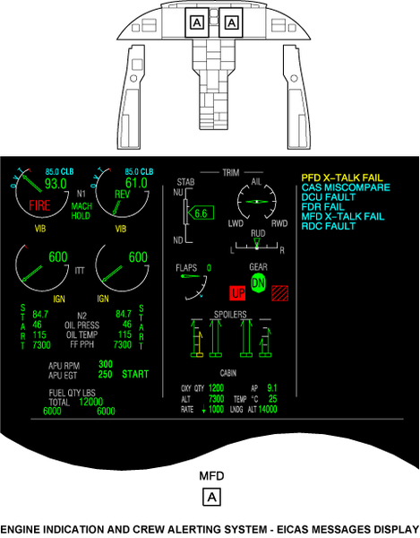
The engine and aircraft systems data, and the CAS messages, show as a full EICAS display on the top half of an multi-function display (MFD). They can also show as a compressed EICAS display on the top half of the primary flight displays (PFDs) or MFDs. The synoptic pages show on the bottom half of an MFD. The summary page shows on the top half of the right MFD or on the bottom half of the PFDs or MFDs. If the left MFD fails, the engine indicating system (EIS) display automatically shows on the right MFD.
The pilot or the copilot can put the same side PFD and MFD together with the LEFT DISPLAYS or RIGHT DISPLAYS reversion switch on the reversion select panel (RSP). This shows a compressed PFD on the serviceable same side display area. The other same side display goes off. The compressed PFD display includes the usual PFD data and EICAS data. The engine indicating system (EIS) display is different from the standard EIS display. It has only an inter-turbine temperature (ITT) digital display in alternative to a digital and an analog displays.
The top part of the two compressed and the full EICAS displays is divided into three parts. The left area is the EIS area, the middle area is the control surface area, and the right area is the CAS message area.
The bottom half of the two MFD can show synoptic pages.

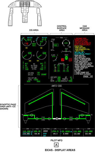
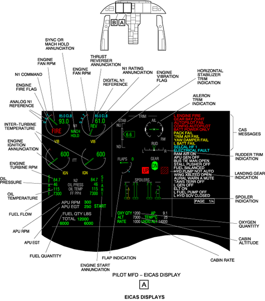
Engine Indication System Area
The EIS area has engine data and engine related annunciations and flags. The full-authority digital engine-control (FADEC) system and the DCU calculate the EIS display data.
The EIS area shows the important engine data that follows:
Engine Fan rpm
The engine fan rpm displays have an analog display and a digital display for each engine. These displays are at the top of the EIS area, and they have an N1 label. Engine fan rpm is shown as a percentage of maximum permitted rpm (100% at 10,156 RPM). The N1 data source is the FADEC system. The analog display that shows engine fan rpm for each of the two engines is an arc scale and a pointer.
When engine fan rpm is at 0%, the pointer is at the three o'clock position. It turns clockwise as rpm increases. At 100%, the scale is approximately at the eleven o'clock position. The scale maximum is at the twelve o'clock position, when the engine fan rpm is at 110%. The digital display that shows the engine fan rpm is above the three o'clock position.
In the EIS area, there are also the N1 command, the N1 reference and the N1 rating annunciations. The N1 command shows as a bug (with a cyan T symbol) in relation to the throttle lever position on the N1 arc scale. The N1 reference shows as a bug and as a digital indication in relation to the throttle rating. The N1 reference bug shows on the arc scale, in one of two possible shapes. It shows as a cyan O symbol (when the throttle rating is CRZ (cruise)) or as a cyan caret (when the throttle rating is APR (automatic power reserve)), TO (takeoff), CLB (climb), MCT (maximum continuous thrust), or REV (reverse thrust)). Bug shape is not shown for all the other conditions. The N1 reference digital-indication shows above the N1 rpm digital-indication. The N1 rating shows as APR, TO, CLB, CRZ, MCT, REV annunciation or no indication in relation to the thrust available for the current throttle notch.
Inter-Turbine Temperature
The ITT displays have an analog and a digital display for each engine. On the compressed PFD display, it shows only as a digital display. These displays are below the engine fan rpm displays in the EIS area. ITT is the temperature in Celsius between specified stages of the engine. The ITT data source is the FADEC system. The ITT analog display for each of the two engines is an arc scale and a pointer.
At 0 °C, the pointer is at the three o'clock position. It turns clockwise as temperature increases. The scale maximum is 1,010 °C. The digital ITT value shows above the three o'clock position.
Engine Turbine rpm
The engine turbine rpm is a digital display for each engine. The engine turbine rpm display has a N2 label. Engine fan rpm is shown as a percentage of maximum permitted rpm (100% at 28,100 rpm). Engine throttle controls the related engine turbine rpm. The N2 data source is the FADEC system.
The engine turbine rpm for the left engine shows below the left ITT arc. The engine turbine rpm for the right engine shows below the right ITT arc. On the compressed PFD display, the engine turbine rpm shows below the ITT digital display. The value can be more than 100%.
Oil Pressure
The oil pressure is a digital display of each engine that shows in psi. The oil pressure display has an OIL PRESS label. The left engine oil pressure shows below the left N2 display. The right engine oil pressure shows below the right N2 display.
Oil Temperature
The oil temperature is a digital display of each engine that shows in Celsius. The oil temperature display has an OIL TEMP label. The left engine oil temperature shows below the oil pressure display of the left engine. The oil temperature of the right engine shows below the right engine oil pressure display.
Fuel Flow
The fuel flow is a digital display for each engine that shows in pounds/hour (pph). The fuel flow display has an FF PPH label. The left engine fuel flow shows below the oil temperature display of the left engine. The right engine fuel flow shows below the oil temperature display of the right engine. The fuel flow data source is the FADEC system. Kilograms/hour (kph) is an optional fuel flow unit. When this unit is set, the display shows FF KPH.
APU rpm
The APU RPM is a digital display. APU RPM is a display of the APU rpm, measured as a percentage of the maximum permitted rpm (100% at 58,737 RPM).
The APU RPM legend goes out of view when the APU is off. The APU RPM is shown below the fuel flow display. The APU rpm data source is the APU electronic control unit (ECU).
APU EGT
The APU EGT is a digital display. APU EGT is the exhaust gas temperature in Celsius of the APU.
The APU EGT legend goes out of view when the APU is off. The APU EGT is shown below the APU rpm display. The APU EGT data source is the APU ECU.
Fuel Quantity
The fuel quantity display is a digital display. The fuel quantity display has a FUEL QTY LBS label. It shows below the APU EGT display. It shows the total fuel quantity and individual wing tank quantities in pounds (LBS). The total fuel quantity has a TOTAL label. The fuel quantity of each tank shows below the TOTAL display.
Kilograms (KGS) is an optional fuel quantity unit. When this unit is set, the display shows FUEL QTY KGS.
Engine Fire Flag
A FIRE flag shows when there is an engine fire condition. The engine FIRE flag shows in the N1 scale of that engine. If FIRE shows, and the N1 pointer is in the same area, FIRE shows on top of the N1 pointer.
Engine Vibration Flag
A VIB flag shows below the N1 display of an engine. It shows when the engine vibration-monitoring unit value is more than a set value.
Engine Ignition Annunciation
An engine IGN annunciation shows below the ITT display of an engine when the engine ignitor is on.
Engine Start Annunciation
An engine START annunciation shows vertically to the left of the N2 display for the left engine and to the right of the N2 display for the right engine when an engine start command is supplied.
Synchronization/Mach Hold Annunciation
A SYNC annunciation shows between the left and right N1 displays when the engine synchronization mode is set. A MACH HOLD annunciation shows between the left and right N1 displays when the Mach hold mode is set. The two annunciations do not show at the same time.
Thrust Reverser Annunciation
A REV annunciation shows in an engine N1 display when the thrust reverser of that engine is deployed.

Control Surface Area
The control surface area is in the middle of the top half of the EICAS display. The control surface area shows the data that follow:
Horizontal Stabilizer Trim Indication
The horizontal stabilizer trim indication shows at the top left of the control surface area. There is a pointer that moves vertically on a scale. Also, there is a digital display within the pointer. The horizontal stabilizer trim shows in trim units (in a range of 0 to 15 trim units). The top of the horizontal-stabilizer trim scale (NU) is 15 trim units. It shows that the aircraft is in the nose-up condition. The bottom of the horizontal-stabilizer trim scale (ND) is zero trim units. It shows that the aircraft is in the nose-down condition. On take-off, there is a take-off band (white rectangle) shown on the scale.
Aileron Trim Indication
The aileron trim indication shows at the top right of the control surface area. It has a linear pointer which simulates the movement of the wings. The scales to the left and right of the pointer have marks each 10 degrees to show the aileron position. When the pointer is in the horizontal position, it shows the 0 degree position. The aileron trim pointer has a display range from 20.0 degrees (LWD) thru -20.0 degrees (RWD). On take-off, there is a take-off band (white rectangle) shown on the scale.
Rudder Trim Indication
The rudder trim indication is below the aileron trim indication. It has a triangular pointer that moves horizontally on a scale. It shows the degrees of the rudder trim tab surface position. The scale has marks each 6.5 degrees. When the pointer is in the center position, it shows the 0 degree position. The rudder trim has a display range from 19.0 degrees (R) thru -19.0 degrees (L). On take-off, there is a take-off band (white rectangle) shown on the scale.
Landing Gear Indication
The landing gear indication is below the rudder trim indication. On the compressed PFD display, the landing gear indication shows at the top right of the control-surface display area. It shows the position of the nose gear, the left main gear, and the right main gear. It has three indicator boxes that indicates the condition of the gears and if the gear is down, up or in transition. The landing gear indication is removed from the display when the flaps and landing gear are fully retracted for more than 30 seconds, and that there are no failure conditions in the two systems.
Flap Indication
The flaps indication is to the left of the landing gear indication. On the compressed PFD display, it shows below the gear indication. It shows the flaps movement on an arc-shaped scale with a pointer. The scale has marks each 10 degrees. The three o’clock position is related to a flaps position of 0 degree (flaps full up). The six o’clock position is related to a flaps position of 30 degrees (flaps full down).
On the outer arc-shaped scale, there is a visual pointer to show the flap set position. There is a digital indication of the flaps degree position adjacent to the legend FLAPS. The flaps indication is removed from the display when the flaps and landing gear are fully retracted for more than 30 seconds, and that there are no failure conditions in the two systems.
Spoiler Indication
The spoilers indication is below the flaps indication and the landing gear indication. The two outboard displays show the left and the right multi-function spoilers (MFS) positions. The two inboard displays show the ground spoilers (GS) position.
The spoilers indication has a box (bottom of the scale), a limit line (top of the scale), and an arrow line to show the position of the spoilers. The arrows on the left MFS scales give the position of the left outboard and left inboard spoilers. The arrows on the right MFS scales give the position of the right outboard and right inboard spoilers. The bottom of the scale is related to the fully retracted position and the top of the scale is related to the fully extended position. The MFS has a display range from 0 degree thru 45 degrees. The scale has marks each 11.25 degrees. The GS has a display range from 0 degree thru 60 degrees. There is no marks on the scale for the GS. It only shows the GS in the fully retracted or fully deployed position.
On the compressed PFD display, the spoilers indication is only text and it shows below the stabilizer trim and rudder trim indications. GND SPLRS DEPLOYED shows when the ground spoilers are deployed. FLT SPLRS DEPLOYED shows when the multi-function spoilers are extended. GND SPLRS/FLT SPLRS show in grey. They show only when the ground spoilers/multi-function spoilers are deployed and go out of view 30 seconds after their retraction. The DEPLOYED indication shows only when the spoilers are deployed.
Oxygen Quantity
The oxygen quantity is a digital display that shows the oxygen quantity in liters.
Cabin Altitude
The cabin altitude (CAB ALT) is a digital display that shows below the spoilers indication. On the compressed PFD display, it shows below the fuel quantity display in the EIS area. It gives the cabin altitude in feet.
Cabin Rate
The cabin rate (CAB RATE) is a digital display that shows below the cabin altitude display. The CAB RATE display shows the rate that the aircraft increases or decreases altitude. This rate shows in feet/minute. It also shows an arrow that points up if the cabin increases its altitude. The arrow points down if the cabin decreases its altitude.
Cabin Differential Pressure
The cabin differential pressure is a digital display that shows the cabin pressure in psi.
Temperature
The temperature is a digital display that shows the temperature of the cabin in Celsius.
Landing Altitude
The landing altitude is a digital display that shows the altitude.
Crew Alerting System Message Area
Messages Level
The CAS shows system messages to the crew in one of four categories in the sequence of how important they are. That sequence is as follows:
- Warning messages first
- Then caution messages
- Then advisory messages
- Then status messages
The warning messages are the messages that require immediately the crew's attention. They are shown in red. The caution messages require immediately the crew's awareness. They are shown in amber. The advisory messages show to the crew a small problem or a decrease in system function. They are shown in cyan. The status messages show to the crew an usual aircraft configuration/performance that requires crew awareness. They are shown in white.
A newest warning message shows at the top of the warning messages. A newest caution message shows at the top of the caution messages. A newest advisory message shows at the top of the advisory messages. A newest status message shows at the top of the status messages.
WARNING/CAUTION Panels Interface
The master warning/caution PBAs are found on the WARNING/CAUTION panels which are part of the glareshield in the flight compartment. The top part of this PBA is a WARNING annunciator and it flashes red when a new CAS warning message is shown. The bottom part is a CAUTION annunciator and it flashes amber when a new CAS caution message is shown. When a new warning/caution message shows on the EICAS, the two master warning/caution PBAs operate with an aural warning. When the PBAs are pushed, or the condition that set the warning/caution is removed, the annunciator stops to flash and the aural warning stops.


Synoptic Pages
The flight crew shows the different synoptic pages on the lower half of an MFD. The A/ICE, ECS, ELEC, FLT, FUEL, HYD, and SUMRY buttons on the CCP show these pages. The cursor control switch on the CCP moves these pages to the left or the right MFD.
When another synoptic page button is pushed, a new page replaces the synoptic page. The FRMT button on the display control panel (DCP) shows the summary page on a compressed PFD. The SUMRY button on the CCP 1 or CCP 2 shows the summary page on the lower half of MFD 1 or MFD 2.
The A/ICE button shows the ANTI-ICE synoptic page. The ECS button shows the environmental control system synoptic page. The ELEC button shows the ELECTRICAL synoptic page. The FLT button shows the FLIGHT CONTROLS synoptic page. The FUEL button shows the FUEL synoptic page. The HYD button shows the HYDRAULIC synoptic page.
The data shown on all synoptic pages follows the same rules and color logic. When a symbol or text is in operation and its condition is correct, it usually shows in green. When the symbol or text is not in operation and its condition is correct, it usually shows in white. When the condition of a symbol or text is in a cautionary status, it usually shows in yellow. When the condition of a symbol or text is in a failure status, it usually shows in red. And when the condition of a symbol or text condition is not valid or not known, it usually shows in magenta.
The synoptic pages include:
Anti-Ice Synoptic Page
The ANTI-ICE synoptic display shows:
- Anti-ice valve condition
- Anti-ice flow duct condition
- Left and right bleed air pressure (in psi).
Anti-ice valves show as a circular outline that has a flow duct that turns. Flow duct color, valve color, and valve position show the wing anti-ice system conditions.

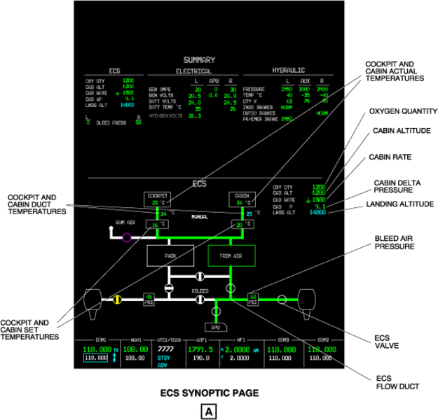
ECS Synoptic Page
The ECS synoptic display shows:
- Left and right bleed air pressure (in psi)
- Cockpit and cabin actual temperature (in Celsius (°C))
- Cockpit and cabin duct temperature (in Celsius)
- Cockpit and cabin set temperature (in Celsius)
- ECS control valve condition
- ECS flow duct condition
- Oxygen quantity (in liters (L))
- Cabin altitude (in feet)
- Cabin direction and rate (in feet per minute)
- Cabin delta pressure (in psi)
- Landing altitude (in feet).
The last five items of the list above show digitally in the top right corner of the ECS synoptic page. The flow duct colors, the valve colors, the valve positions, and digital values show ECS conditions.
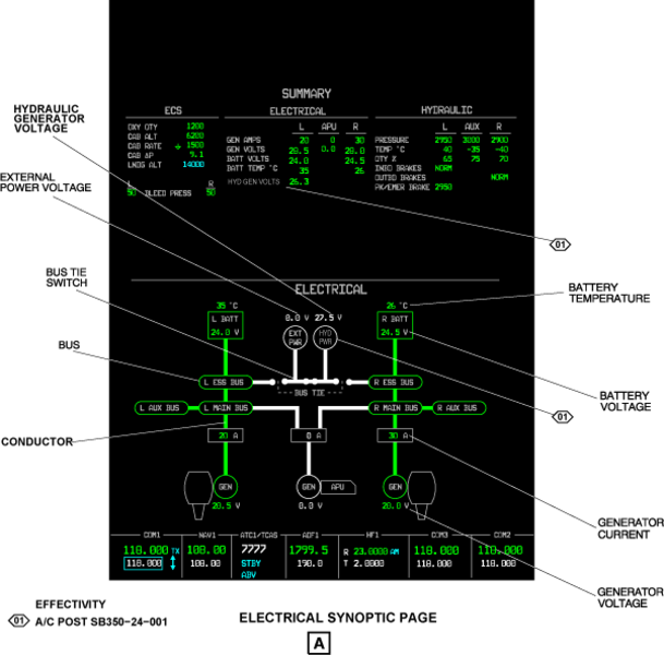
Electrical Synoptic Page
The ELECTRICAL synoptic display shows:
- Left and right batteries voltage (in volts (V)), temperature (in Celsius (°C)) and condition
- External power voltage (in volts) and condition
- Left/right engines and APU generators voltage (in volts), current (in amps (A)) and condition
- Bus tie switch
- Bus condition
- Conductor condition.
The conductors color, bus color, battery color, and measurements show the electrical system conditions.
Note:
The data on the standby instrument battery is not shown on the synoptic page.
Flight Controls Synoptic Page
The FLIGHT CONTROLS synoptic display shows:
- Left and right ailerons
- Left and right elevators
- Rudder
- Left and right spoilers
- Left and right flaps.
The left and right aileron displays have pointers. The pointers move up when the aileron moves up, and the pointers move down when the aileron moves down.
The left and right elevator displays have pointers. The pointers move up when the elevator moves up, and the pointers move down when the elevator moves down.
The rudder display is between the elevator displays. It shows the degrees of the rudder trim tab surface position.
The spoiler displays show the left and the right MFS positions. They also show the GS position. The spoiler displays in the synoptic page and in the control surface area are the same.
The flap displays show a digital indication of the angle that the left and right flaps are at.
The flight controls positions, colors, and values show the flight control system conditions.

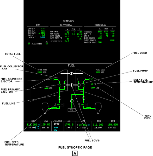
Fuel Synoptic Page
The FUEL synoptic display shows:
- Total fuel (in pounds or kilograms (LBS or KG))
- Left wing and right wing fuel (in pounds or kilograms (LBS or KG))
- Fuel used (in pounds or kilograms (LBS or KG))
- Left and right fuel feed temperatures (in Celsius (°C))
- Bulk fuel temperature (in Celsius)
- Fuel line condition
- Fuel shutoff valve (SOV) condition
- Left and right fuel collector tanks
- Left and right fuel primary ejectors condition
- Left and right fuel scavenge ejectors condition
- Left and right fuel pumps.
The duct color, valve color, valve position, and measurements show the fuel system conditions.
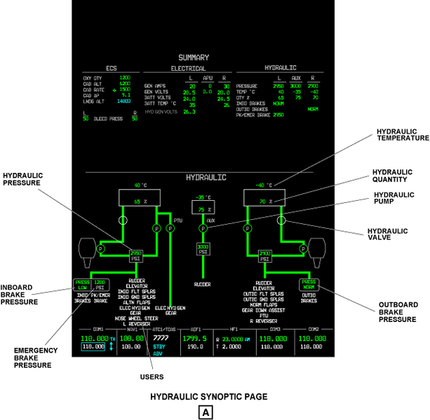
Hydraulic Synoptic Page
The HYDRAULIC synoptic display shows:
- Left, right, and auxiliary hydraulic quantities (in % value), temperatures (in Celsius (°C)) and pressures (in psi)
- Left, right, and auxiliary hydraulic pumps condition
- Left and right hydraulic valves condition
- Inboard and outboard brakes condition
- Emergency brake pressure
- Users of the hydraulic system and their condition.
The color, pump color, valve color, valve position, users color, and measurements show the hydraulic system conditions.
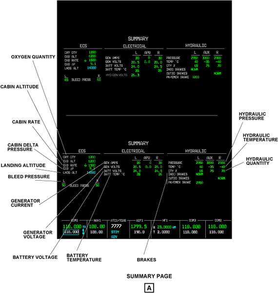
Summary Page
The SUMRY button on the CCP 1 or CCP 2 shows the summary page on MFD 1 or MFD 2. The FRMT button, on the DCP, can also show the summary page in the lower half of the compressed PFD. The summary page shows data from the ECS synoptic page, the ELECTRICAL synoptic page, and the HYDRAULIC synoptic page.
The SUMMARY page shows:
- Oxygen quantity (in liters)
- Cabin altitude (in feet)
- Cabin rate (in feet per minute)
- Cabin delta pressure (in psi)
- Landing altitude (in feet)
- Left and right bleed pressures (in psi)
- Left, right and APU generator currents (in amps)
- Left, right and APU generator voltages (in volts)
- Left and right battery voltages (in volts)
- Left and right battery temperatures (in Celsius)
- Left, right, and auxiliary hydraulic pressures (in psi)
- Left, right, and auxiliary hydraulic temperatures (in Celsius)
- Left, right, and auxiliary hydraulic quantity (in % value)
- Inboard brakes condition
- Outboard brakes condition
- Park/emergency brake condition
- Hydraulic generator voltage (in volts)
EICAS Messages List
A list of EICAS messages is contained in the table that follows. The table gives the related conditions for each message which is supplied to the logic circuit of the DCU. This list is given in the sequence of ATA chapters. The priority level of each message is shown by their levels as follows:
- Warning
- Caution
- Advisory
- Status
|
EICAS MESSAGES |
LEVEL |
SIMPLIFIED LOGIC |
|---|---|---|
|
CHAPTER 21 |
||
|
CABIN ALTITUDE |
WARNING |
Cabin altitude is more that the warning threshold |
|
CABIN DELTA P |
WARNING |
Cabin ΔP is more than 9.2 psid or less than −0.3 psid |
|
AIR COND TEMP FAIL |
CAUTION |
One of the two VENTS has failed while in automatic mode |
|
AIR COND TEMP HIGH |
CAUTION |
An excessive air temperature has been sensed in the cabin or cockpit air distribution ducts |
|
AUTO PRESS FAIL |
CAUTION |
The automatic pressurization modes have failed or no data is received from IAS controllers |
|
CABIN ALTITUDE |
CAUTION |
Cabin altitude is more that the caution threshold |
|
CABIN PRESS FAULT |
CAUTION |
The cabin altitude limitation function has failed on IAS controller No. 1 or No. 2 |
|
DITCHING NOT AVAIL |
CAUTION |
The DITCHING PBA on the PRESSURIZATION control panel is pushed and the pressurization system is in manual mode |
|
EQPT RACK TEMP HIGH |
CAUTION |
The temperature in one of the two equipment racks is high |
|
PACK FAIL |
CAUTION |
The TCV has failed or the two elements in the CTDS and PTDS have failed |
|
PACK TEMP HIGH |
CAUTION |
An overheat has been sensed by the CTDS or PTDS |
|
TRIM AIR FAIL |
CAUTION |
A HARSOV has failed or one of the DTS is out of range or send no data |
|
AIR COND FAULT |
ADVISORY |
One of the two elements of the CDTS, PTDS, or PTS has failed |
|
CABIN ALT WARN HIGH |
ADVISORY |
A high airport take-off or landing has been initiated and the pressurization system is in the automatic mode |
|
EQPT RACK COOL FAULT |
ADVISORY |
A fault has been sensed in the avionics equipment rack cooling system |
|
MANUAL PRESS FAIL |
ADVISORY |
The manual mode does not operate (on the ground only) |
|
PACK COOL AIR FAIL |
ADVISORY |
The ram air regulating valve has failed |
|
RAM AIR FAIL |
ADVISORY |
The position of the ram air valve does not agree with the RAM AIR selection made on the AIR COND/BLEED control panel |
|
AIR COND MAN TEMP ON |
STATUS |
The MAN PBA on the AIR COND/BLEED control panel is pushed and the PBA light comes on |
|
AIR SOURCE OFF |
STATUS |
The AIR SOURCE switch on the AIR COND/BLEED control panel is in the OFF position |
|
DITCHING ON |
STATUS |
The DITCHING PBA on the PRESSURIZATION control panel is pushed and the pressurization system is in automatic mode |
|
EMER DEPRESS ON |
STATUS |
The EMER DEPRESS PBA on the PRESSURIZATION control panel is pushed |
|
MANUAL PRESS ON |
STATUS |
The MANUAL PBA on the PRESSURIZATION control panel is pushed and the system operates in manual mode |
|
PACK ONLY |
STATUS |
The AIR SOURCE switch on the AIR COND/BLEED control panel is in the PACK ONLY position |
|
RAM AIR ON |
STATUS |
The RAM AIR PBA on the AIR COND/BLEED control panel is pushed and the ram air valve is open |
|
TRIM AIR ONLY |
STATUS |
The AIR SOURCE switch on the AIR COND/BLEED control panel is in the TRIM AIR ONLY position |
|
CHAPTER 22 |
||
|
CONFIG AUTOPILOT |
WARNING |
Autopilot is engaged and the aircraft is in take-off configuration |
|
AFCS MESSAGES FAIL |
CAUTION |
The AFCS has lost the function to show messages |
|
AP HOLDING LWD |
CAUTION |
The autopilot holds left wing down control force |
|
AP HOLDING NOSE DOWN |
CAUTION |
The autopilot holds nose down control force |
|
AP HOLDING NOSE UP |
CAUTION |
The autopilot holds nose up control force |
|
AP HOLDING RWD |
CAUTION |
The autopilot holds right wing down control force |
|
AP STAB TRIM FAIL |
CAUTION |
The autopilot cannot make a trim correction to the horizontal stabilizer |
|
FD MODE CHANGE |
CAUTION |
An inadvertent FD mode change has occurred |
|
YAW DAMPER FAIL |
CAUTION |
Yaw damper has failed |
|
FD 1 FAIL |
ADVISORY |
The flight director 1 has failed |
|
FD 2 FAIL |
ADVISORY |
The flight director 2 has failed |
|
YAW DAMPER OFF |
STATUS |
Yaw damper is set off (yaw damper not engaged) |
|
CHAPTER 23 |
||
|
CVR FAIL |
ADVISORY |
The CVR has a fault |
|
DATALINK CPDLC ATN |
ADVISORY |
A CPDLC message has been received and accompanied by a chime (Link 2000+ function) Replaces DATALINK CPDLC |
|
DATALINK CPDLC FANS |
ADVISORY |
A new CPDLC message has been received or an uncommanded loss of CPDLC connection, accompanied by a chime (Post FANS) |
|
DATALINK ACARS |
ADVISORY |
A DATALINK message has been received and accompanied by a chime if the message is in response to an outgoing request (DATALINK ACARS for Link 2000+ function) |
|
SELCAL DATALINK |
ADVISORY |
A SELCAL code has been received on Datalink |
|
SELCAL HF1 |
ADVISORY |
A SELCAL code has been received on HF 1 |
|
SELCAL HF2 |
ADVISORY |
A SELCAL code has been received on HF 2 |
|
SELCAL VHF1 |
ADVISORY |
A SELCAL code has been received on VHF 1 |
|
SELCAL VHF2 |
ADVISORY |
A SELCAL code has been received on VHF 2 |
|
SELCAL VHF3 |
ADVISORY |
A SELCAL code has been received on VHF 3 |
|
DATALINK FANS FAIL |
ADVISORY |
The datalink CPDLC FANS functionality has failed |
|
DATALINK FAIL |
ADVISORY |
The datalink functionality has failed |
|
CHAPTER 24 |
||
|
L BATT OVERHEAT |
WARNING |
Left battery internal temperature is high |
|
R BATT OVERHEAT |
WARNING |
Right battery internal temperature is high |
|
ESSENTIAL POWER ONLY |
WARNING |
Both engines and APU driven generator are off line |
|
APU GEN FAIL |
CAUTION |
The APU generator has failed |
|
APU GEN OVERLOAD |
CAUTION |
The APU generator load is more than 500 amps |
|
L BATT FAIL |
CAUTION |
The left battery has failed, or the battery contactor has failed, or the battery has been automatically disconnected for overheat protection |
|
R BATT FAIL |
CAUTION |
The right battery has failed, or the battery contactor has failed, or the battery has been automatically disconnected for overheat protection |
|
ELEC HYD GEN FAIL |
CAUTION |
HMDG is selected on, but the HMDG line contactor is not closed |
|
ELEC HYD GEN ON |
STATUS |
The hydraulic generator line contactor is closed |
|
ELECTRICAL FAULT |
CAUTION |
An electrical system failure has occurred that prevents the display of electrical indications |
|
L ESS BUS FAIL |
CAUTION |
The left essential bus is not powered with a power source available |
|
R ESS BUS FAIL |
CAUTION |
The right essential bus is not powered with a power source available |
|
L GEN FAIL |
CAUTION |
The left generator has failed |
|
R GEN FAIL |
CAUTION |
The right generator has failed |
|
L GEN OVERLOAD |
CAUTION |
The left generator load is more than 500 amps |
|
R GEN OVERLOAD |
CAUTION |
The right generator load is more than 500 amps |
|
L MAIN BUS FAIL |
CAUTION |
The left MAIN bus is not powered with a power source available |
|
R MAIN BUS FAIL |
CAUTION |
The right MAIN bus is not powered with a power source available |
|
L AUX BUS FAIL |
ADVISORY |
The left auxiliary bus is not powered with a power source available |
|
R AUX BUS FAIL |
ADVISORY |
The right auxiliary bus is not powered with a power source available |
|
L AUX BUS OFF |
ADVISORY |
Left side of the electrical system is selected off |
|
R AUX BUS OFF |
ADVISORY |
Right side of the electrical system is selected off |
|
ELECTRICAL FAULT |
ADVISORY |
An electrical system fault has occurred that causes the loss of redundancy in the display of electrical indications |
|
L ESS BUS OFF |
ADVISORY |
Left side of the ESS electrical system is selected off |
|
R ESS BUS OFF |
ADVISORY |
Right side of the ESS electrical system is selected off |
|
L MAIN BUS OFF |
ADVISORY |
Left side of the MAIN electrical system is selected off |
|
R MAIN BUS OFF |
ADVISORY |
Right side of the MAIN electrical system is selected off |
|
STBY INST BATT FAULT |
ADVISORY |
The MAINTENANCE TEST switch on the MAINTENANCE PANEL has been set to ISI BATT FAULT position |
|
APU GEN OFF |
STATUS |
The APU generator has been set OFF |
|
L BATT OFF |
STATUS |
The left battery has been set OFF |
|
R BATT OFF |
STATUS |
The right battery has been set OFF |
|
BUS TIE MAN OPEN |
STATUS |
The bus tie has been manually set open |
|
L GEN OFF |
STATUS |
The left engine generator switch has been set OFF |
|
R GEN OFF |
STATUS |
The right engine generator switch has been set OFF |
|
STBY INST OFF |
STATUS |
The STBY INST PBA has been pushed |
|
CHAPTER 25 |
||
|
ACARS MESSAGE |
ADVISORY |
An ARINC communications addressing and reporting system message has been received (SATCOM option or completion center installed item) |
|
AFIS MESSAGE |
ADVISORY |
An airborne flight information system message has been received (SATCOM option or completion center installed item) |
|
CABIN CALL |
ADVISORY |
A call has been made from the cabin (Completion center installed item) |
|
FAX RECEIVED |
ADVISORY |
A fax has been received (Completion center installed item) |
|
LAV CALL |
ADVISORY |
A call has been made from the lavatory (Completion center installed item) |
|
ELT ON |
STATUS |
ELT transmits |
|
CHAPTER 26 |
||
|
APU FIRE |
WARNING |
One of the fire detection loops on the APU has sensed a fire |
|
CARGO SMOKE |
WARNING |
Smoke has been sensed in the cargo (baggage) area |
|
L ENGINE FIRE |
WARNING |
One of fire detection loops on the left engine has sensed a fire |
|
R ENGINE FIRE |
WARNING |
One of fire detection loops on the right engine has sensed a fire |
|
GEAR BAY OVHT |
WARNING |
An overheat condition has been sensed in the MWW |
|
APU FIRE DET FAIL |
CAUTION |
The APU fire detection system has failed |
|
CARGO SMOKE DET FAIL |
CAUTION |
The baggage compartment smoke detection system has failed |
|
L FIRE DET FAIL |
CAUTION |
The left engine fire detection system has failed |
|
R FIRE DET FAIL |
CAUTION |
The right engine fire detection system has failed |
|
FIRE SYS FAULT |
CAUTION |
The fire detection and extinguishing system has detected a fault |
|
FIREX APU SQUIB FAIL |
CAUTION |
The APU fire extinguishing container squib on bottle No. 2 has failed (no low pressure indication) |
|
GEAR BAY DET FAIL |
CAUTION |
The MWW overheat detection has failed |
|
FIRE SYS FAULT |
ADVISORY |
The FIREX-CU has sensed a fault |
|
FIREX BTL 1 FAULT |
ADVISORY |
The left container squib for the left or right engine has failed |
|
FIREX BTL 2 FAULT |
ADVISORY |
The right container squib for the left or right engine has failed |
|
FIREX BTL 1 LOW |
ADVISORY |
Fire extinguishing container No. 1 pressure is low |
|
FIREX BTL 2 LOW |
ADVISORY |
Fire extinguishing container No. 2 pressure is low |
|
FIRE SYS IN TEST |
STATUS |
The fire detection system is in pilot initiated test |
|
FIRE SYS TEST OK |
STATUS |
The fire detection system test is satisfactory |
|
CHAPTER 27 |
||
|
CONFIG AILERON TRIM |
WARNING |
Aircraft is on ground for 30 seconds and the aileron trim is not correctly configured for take-off |
|
CONFIG FLAPS |
WARNING |
Aircraft is on ground and the flaps are not correctly configured for take-off |
|
CONFIG RUDDER TRIM |
WARNING |
Aircraft is on ground for 30 seconds and the rudder trim is not correctly configured for take-off |
|
CONFIG SPOILERS |
WARNING |
Aircraft is on ground and the spoilers are not correctly configured for take-off |
|
CONFIG STAB TRIM |
WARNING |
Aircraft is on ground and the stabilizer trim is not correctly configured for take-off |
|
PITCH DISCONNECT |
WARNING |
Pitch disconnect has occurred when the aircraft is in take-off configuration |
|
ROLL DISCONNECT |
WARNING |
Roll disconnect has occurred when the aircraft is in take-off configuration |
|
ELEVATOR SPLIT |
CAUTION |
The elevator has a split of more than 7.5 degrees |
|
FLAPS FAIL |
CAUTION |
The FCU senses a malfunction in the flap system which can not be corrected in flight |
|
FLAPS FAULT |
CAUTION |
The FCU senses a malfunction in the flap system which can be corrected in flight |
|
FLAPS NORM PRESS LOW |
CAUTION |
The flaps normal hydraulic pressure is low |
|
FLT SPOILERS DEPLOY |
CAUTION |
The flight spoilers are deployed below 500 ft (not on ground) and/or the throttles are above idle (not on ground) |
|
FLT SPOILERS FAIL |
CAUTION |
The flight spoilers have failed |
|
FLT SPOILERS FAULT |
CAUTION |
The inboard or outboard flight spoilers have failed |
|
GND SPLRS NOT ARMED |
CAUTION |
The ground spoilers are not armed and not set OFF |
|
GND SPOILERS FAIL |
CAUTION |
The ground spoilers have failed |
|
MACH TRIM FAIL |
CAUTION |
The Mach trim has failed |
|
PRI STAB TRIM FAIL |
CAUTION |
The primary channel of the stab trim has failed |
|
ROLL SPOILERS FAIL |
CAUTION |
The roll assist function has failed |
|
ROLL SPOILERS FAULT |
CAUTION |
The inboard or outboard roll spoilers have failed |
|
ROLL SPOILERS OFF |
CAUTION |
The roll spoiler switch is set to OFF and the roll disconnect switch is not set to disconnect |
|
RUDDER LIMITER FAIL |
CAUTION |
The rudder limiter has failed |
|
SEC STAB TRIM FAIL |
CAUTION |
The secondary channel of the stab trim has failed |
|
SPOILERS FAIL |
CAUTION |
The spoilers have failed |
|
SPOILERS FAULT |
CAUTION |
One or more of the spoiler PCU panels have failed, or one or more of the ground spoilers is up prior to touchdown |
|
STALL PROTECT FAIL |
CAUTION |
The SPC has sensed a fail condition |
|
STALL PUSHER OFF |
CAUTION |
The MSW on one or the other control wheel has been pushed for longer than 10s |
|
FLAPS FAULT |
ADVISORY |
There is a small malfunction in the flap system which does not stop the operation of the flaps |
|
FLAPS RATE LOW |
ADVISORY |
The FCU controls the flap system at a lower speed than the nominal speed |
|
RUDDER LIMITER FAULT |
ADVISORY |
A minor failure that causes the loss of redundancy has occurred in the rudder limiter system |
|
SPOILERS FAULT |
ADVISORY |
A fault that causes the loss of redundancy has occurred in the spoiler system but does not affect spoiler operation |
|
STAB TRIM FAULT |
ADVISORY |
The system has lost redundancy |
|
STALL PROTECT FAULT |
ADVISORY |
The SPC has sensed a fault and has reverted to a default flap settings of 30 degrees |
|
L STALL SHAKER FAIL |
ADVISORY |
The left stall shaker has failed |
|
R STALL SHAKER FAIL |
ADVISORY |
The right stall shaker has failed |
|
STALL WARN BASIC |
ADVISORY |
The SPC has incorrectly reverted to primary mode |
|
GND SPOILERS OFF |
STATUS |
The ground spoilers are set OFF |
|
PITCH DISCONNECT |
STATUS |
Pitch disconnect has occurred when the aircraft is not in take-off configuration |
|
ROLL DISCONNECT |
STATUS |
Roll disconnect has occurred when the aircraft is not in take-off configuration |
|
ROLL SPOILERS OFF |
STATUS |
The roll spoiler switch is set to OFF and the roll disconnect switch is set to disconnect |
|
RUD LIMITER IN TEST |
STATUS |
The rudder travel limiter system does the manually started system test |
|
SEC STAB TRIM ON |
STATUS |
The secondary channel of the horizontal stabilizer (pitch) trim system is selected and the secondary channel is operative |
|
STAB TRIM OFF |
STATUS |
The STAB TRIM switch is set OFF |
|
STALL PUSHER OFF |
STATUS |
The MSW on one or the other control wheel has been pushed for less than 10 seconds or the pusher has been inhibited by the STALL PUSHER PBA |
|
CHAPTER 28 |
||
|
APU FUEL SOV FAIL |
CAUTION |
The SOV has failed to open/close in 5s or less of command signal |
|
L ENG FUEL SOV FAIL |
CAUTION |
The left engine SOV has failed to open/close in 5s or less of command signal |
|
R ENG FUEL SOV FAIL |
CAUTION |
The right engine SOV has failed to open/close in 5s or less of command signal |
|
L FUEL COLLECTOR LOW |
CAUTION |
Quantity in the collector is less than 200 lb (90.72 kg) for a minimum of 10s with engine running |
|
R FUEL COLLECTOR LOW |
CAUTION |
Quantity in the collector is less than 200 lb (90.72 kg) for a minimum of 10s with engine running |
|
L FUEL EJECTOR FAIL |
CAUTION |
The outlet pressure of the ejector is low for a minimum of 5s with the engine running |
|
R FUEL EJECTOR FAIL |
CAUTION |
The outlet pressure of the ejector is low for a minimum of 5s with the engine running |
|
FUEL IMBALANCE |
CAUTION |
The wing fuel balance is out of the usual range |
|
L FUEL PUMP FAIL |
CAUTION |
The left electric fuel pump has failed |
|
R FUEL PUMP FAIL |
CAUTION |
The right electric fuel pump has failed |
|
FUEL QUANTITY FAIL |
CAUTION |
The two channels of the fuel quantity conditioning unit have failed |
|
FUEL QUANTITY LOW |
CAUTION |
The fuel quantity is 500 lb (226.80 kg) or less in one of the two wings, when the aircraft is in unaccelerated, level flight |
|
WING FUEL TEMP LOW |
CAUTION |
The fuel temperature in the wing is low (−38.2 °C (−36.7 °F)) |
|
FUEL GRAV XFLOW FAIL |
ADVISORY |
The gravity-crossflow SOV is not opened/closed in 5s or less of command signal |
|
L FUEL PUMP ON |
ADVISORY |
Left fuel pump is automatically turned ON |
|
R FUEL PUMP ON |
ADVISORY |
Right fuel pump is automatically turned ON |
|
FUEL QUANTITY FAULT |
ADVISORY |
The left or right channel has sensed a fault |
|
FUEL XFER FAIL |
ADVISORY |
The wing-transfer SOV is not opened/closed in 5s or less of command signal |
|
L ENG FUEL SOV CLSD |
STATUS |
The left engine SOV is closed |
|
R ENG FUEL SOV CLSD |
STATUS |
The right engine SOV is closed |
|
FUEL BALANCED |
STATUS |
The fuel is balanced within 100 lb with the fuel transfer valve open |
|
FUEL GRAV XFLOW OPEN |
STATUS |
The wing fuel gravity crossflow valve is open |
|
L FUEL PUMP OFF |
STATUS |
The left pump is OFF |
|
R FUEL PUMP OFF |
STATUS |
The right pump is OFF |
|
L FUEL PUMP ON |
STATUS |
The left pump is ON |
|
R FUEL PUMP ON |
STATUS |
The right pump is ON |
|
FUEL XFER OPEN |
STATUS |
The fuel transfer valve is open |
|
CHAPTER 29 |
||
|
HYD PRESS LOW |
WARNING |
The left and right hydraulic pressures are low |
|
AUX HYD TEMP HIGH |
CAUTION |
The auxiliary hydraulic system temperature is high |
|
L HYD PRESS LOW |
CAUTION |
Left hydraulic system pressure is low |
|
R HYD PRESS LOW |
CAUTION |
Right hydraulic system pressure is low |
|
HYD PTU FAIL |
CAUTION |
The PTU does not operate when the left hydraulic system pressure is low |
|
L HYD SOV FAIL |
CAUTION |
The left hydraulic SOV did not close when one of the following occurred:- The left ENG FIRE switch was pressed- The left hydraulic SOV switch was set CLOSED- The automatic overtemp closure was commanded |
|
R HYD SOV FAIL |
CAUTION |
The right hydraulic SOV did not close when one of the following occurred:- The right ENG FIRE switch was pressed- The right hydraulic SOV switch was set CLOSED- The automatic overtemp closure was commanded |
|
L HYD TEMP HIGH |
CAUTION |
Left hydraulic system temperature is high |
|
R HYD TEMP HIGH |
CAUTION |
Right hydraulic system temperature is high |
|
AUX HYD PUMP FAIL ON |
ADVISORY |
The auxiliary hydraulic pump is running continuously |
|
AUX HYD SYS FAIL |
ADVISORY |
The auxiliary hydraulic pump does not operate |
|
L HYD DC PUMP FAIL |
ADVISORY |
The left hydraulic DC pump does not pressurize the system |
|
R HYD DC PUMP FAIL |
ADVISORY |
The right hydraulic DC pump does not pressurize the system |
|
L HYD ENG PUMP FAIL |
ADVISORY |
The left hydraulic engine pump does not pressurize the system |
|
R HYD ENG PUMP FAIL |
ADVISORY |
The right hydraulic engine pump does not pressurize the system |
|
L HYD SOV CLOSED |
ADVISORY |
The left hydraulic SOV is closed because of an automatic system command |
|
R HYD SOV CLOSED |
ADVISORY |
The right hydraulic SOV is closed because of an automatic system command |
|
HYD PUMP NOT AUTO |
STATUS |
At least one HYDRAULIC PUMP (L, R, PTU or AUX) switch is not in the AUTO position |
|
L HYD SOV CLOSED |
STATUS |
The left hydraulic SOV is closed because of a manual command |
|
R HYD SOV CLOSED |
STATUS |
The right hydraulic SOV is closed because of a manual command |
|
CHAPTER 30 |
||
|
L WING OVERHEAT |
WARNING |
A wing anti-ice overheat condition exists in the left wing |
|
R WING OVERHEAT |
WARNING |
A wing anti-ice overheat condition exists in the right wing |
|
L AOA VANE HEAT FAIL |
CAUTION |
The left AOA vane heater has failed |
|
R AOA VANE HEAT FAIL |
CAUTION |
The right AOA vane heater has failed |
|
L ENG ANTI-ICE FAIL |
CAUTION |
Bleed air pressure to the left nacelle is too low for effective anti-icing, or the electrically heated TT2 heater has failed when the L ENG PBA is ON |
|
R ENG ANTI-ICE FAIL |
CAUTION |
Bleed air pressure to the right nacelle is too low for effective anti-icing, or the electrically heated TT2 heater has failed when the R ENG PBA is ON |
|
ICE DETECTED |
CAUTION |
Ice has been sensed, and the engine and wing anti-ice systems are not set on |
|
ICE DETECTOR FAIL |
CAUTION |
The two ice detectors have failed |
|
L PITOT HEAT FAIL |
CAUTION |
Left pitot mast or base heater has failed |
|
R PITOT HEAT FAIL |
CAUTION |
Right pitot mast or base heater has failed |
|
L PROBE HEAT OFF |
CAUTION |
Left probe heat is off |
|
R PROBE HEAT OFF |
CAUTION |
Right probe heat is off |
|
STBY PITOT HEAT FAIL |
CAUTION |
Standby pitot heater has failed |
|
L STBY STAT HT FAIL |
CAUTION |
The left standby static heater has failed |
|
R STBY STAT HT FAIL |
CAUTION |
The right standby static heater has failed |
|
L WINDOW HEAT FAIL |
CAUTION |
The left window heat has failed and the temperature is too low or too high |
|
R WINDOW HEAT FAIL |
CAUTION |
The right window heat has failed and the temperature is too low or too high |
|
L WING A/I LOW TEMP |
CAUTION |
A low temperature condition is sensed by the left leading-edge temperature sensor |
|
R WING A/I LOW TEMP |
CAUTION |
A low temperature condition is sensed by the right leading-edge temperature sensor |
|
L WING A/I PRESS HI |
CAUTION |
High pressure condition is sensed downstream the left HPV |
|
R WING A/I PRESS HI |
CAUTION |
High pressure condition is sensed downstream the right HPV |
|
L WING ANTI-ICE FAIL |
CAUTION |
A low temperature condition is sensed by the left leading-edge temperature sensor |
|
R WING ANTI-ICE FAIL |
CAUTION |
A low temperature condition is sensed by the left leading-edge temperature sensor |
|
WING ANTI-ICE FAULT |
CAUTION |
The two channels of the left or right leading-edge temperature sensor are failed |
|
L WSHLD HEAT FAIL |
CAUTION |
The left windshield heat has failed and temperature is too low or to high |
|
R WSHLD HEAT FAIL |
CAUTION |
The right windshield heat has failed and temperature is too low or to high |
|
L AOA CASE HEAT FAIL |
ADVISORY |
The left AOA case heater has failed |
|
R AOA CASE HEAT FAIL |
ADVISORY |
The right AOA case heater has failed |
|
L ENG A/ICE FAIL ON |
ADVISORY |
The left cowl anti-ice valve is sensed defective or the left engine inlet temperature (TT2) sensor is sensed defective. Because one of these conditions occurs, the nacelle anti-ice system operates without being commanded to |
|
R ENG A/ICE FAIL ON |
ADVISORY |
The right cowl anti-ice valve is sensed defective or the right engine inlet temperature (TT2) sensor is sensed defective. Because one of these conditions occurs, the nacelle anti-ice system operates without being commanded to |
|
ICE DETECTED |
ADVISORY |
Ice has been sensed and the engine and wing anti-ice systems are set on |
|
ICE DETECTOR FAULT |
ADVISORY |
One ice detector has failed |
|
L PROBE HT CTLR FAIL |
ADVISORY |
The left probe heat controller has failed |
|
R PROBE HT CTLR FAIL |
ADVISORY |
The right probe heat controller has failed |
|
TAT HEAT FAIL |
ADVISORY |
The TAT probe heater has failed |
|
WING ANTI-ICE FAULT |
ADVISORY |
An inboard or outboard leading-edge sensor is failed |
|
WING SOURCE-XBLEED |
ADVISORY |
The CBV is in the fully opened position, the WING SOURCE switch is set to NORMAL and the anti-ice system is on |
|
ENG ANTI-ICE ON |
STATUS |
The two ANTI-ICE ENG PBAs are set ON |
|
L ENG ANTI-ICE ON |
STATUS |
The left ANTI-ICE ENG PBA is set ON |
|
R ENG ANTI-ICE ON |
STATUS |
The right ANTI-ICE ENG PBA is set ON |
|
PROBE HEAT TEST OK |
STATUS |
The pilot initiated probe heat test is satisfactory |
|
WING ANTI-ICE ON |
STATUS |
The WING ANTI-ICE PBA is set ON |
|
WING/ENG ANTI-ICE ON |
STATUS |
The wing and both engine anti-ice systems are ON |
|
WING SOURCE-XBLEED |
STATUS |
The CBV is in the fully opened position, the WING SOURCE switch is not set to NORMAL and the anti-ice system is on |
|
CHAPTER 31 |
||
|
EFIS COMPARATOR INOP |
CAUTION |
EFIS comparator is unable to compare one or more of the parameters that follow: altitude, airspeed, roll attitude, pitch attitude, heading, radio altitude, flight director, localizer or glideslope |
|
EFIS MISCOMPARE |
CAUTION |
There is a mismatch between the same side and opposite side data |
|
L ENG DSPL MISCOMP |
CAUTION |
There has been a mis-compare of engine related flight critical parameters |
|
R ENG DSPL MISCOMP |
CAUTION |
There has been a mis-compare of engine related flight critical parameters |
|
L IAPS FAIL |
CAUTION |
The DCU does not receive valid data from the left IOC or the PWR has stopped to operate |
|
R IAPS FAIL |
CAUTION |
The DCU does not receive valid data from the right IOC or the PWR has stopped to operate |
|
PFD X-TALK FAIL |
CAUTION |
Communication between the PFDs has failed |
|
CAS MISCOMPARE |
ADVISORY |
There has been a miscompare of warning, caution, advisory, status or aural warnings for more than 20 seconds. All CAS messages will be shown and aural warnings heard |
|
DCU FAN FAIL |
ADVISORY |
DCU fan has failed |
|
DCU FAULT |
ADVISORY |
Channel A or B in the DCU has failed |
|
FDR FAIL |
ADVISORY |
The FDR has failed |
|
FDR FAULT |
ADVISORY |
The longitudinal, lateral or vertical accelerations parameters in the FDR are inoperative |
|
IAPS FAN FAULT |
ADVISORY |
IAPS has detected a fan failure, over-temperature, or a temperature sensor failure |
|
MFD X-TALK FAIL |
ADVISORY |
Communication between the MFDs has failed |
|
RDC FAN FAIL |
ADVISORY |
RDC Fan has failed |
|
RDC FAULT |
ADVISORY |
Channel A or B of the RDC has failed with no loss of functionality |
|
AURAL WARN A MUTED |
STATUS |
The AURAL WARNING DCU A switch has been set |
|
AURAL WARN B MUTED |
STATUS |
The AURAL WARNING DCU B switch has been set |
|
CHAPTER 32 |
||
|
GEAR |
WARNING |
1. Accompanied with a non-mutable “GEAR” aural warning indicates a radar altitude of less than 500 ft and throttles below climb (CLB) or flaps at 30 with any gear not down.2. Accompanied with the radar altitude failed and a mutable “GEAR” aural warning indicates the following:- Any gear is not down and- an altitude of less than 15 000, throttles below climb (CLB) with- IAS below 170 kts and flaps at 0 degree or- IAS below 160 kts and flaps at 10 degrees or- IAS below 155 kts and flaps at 20 degrees. |
|
NORM BRAKES FAIL |
WARNING |
All normal brakes have failed |
|
PARK/EMER BRAKE ON |
WARNING |
The PARK/EMER BRAKE is engaged while in take-off configuration |
|
CPLT BRAKE FAULT |
CAUTION |
One or more of the copilot brake pedal sensors (LVDTs) has failed |
|
GEAR DISAGREE |
CAUTION |
This indicates that the gear position and the landing gear control handle position do not match |
|
GEAR SYS FAIL |
CAUTION |
This indicates a complete failure of the gear control or the loss of the ARINC 429 signal from the two channels |
|
L INBD BRAKE FAIL |
CAUTION |
The left inboard system brake has failed |
|
R INBD BRAKE FAIL |
CAUTION |
The right inboard system brake has failed |
|
INBD BRAKE PRESS LO |
CAUTION |
The inboard brake accumulator pressure is low |
|
INBD BRAKES FAIL |
CAUTION |
The two inboard system brakes have failed |
|
NOSE GEAR DOOR |
CAUTION |
At least one of the nose gear doors are not closed and the nose gear is up |
|
NWS FAIL |
CAUTION |
The nose wheel steering system has failed |
|
NWS LIMIT EXCEEDED |
CAUTION |
The nose wheel steering turning limit has been exceeded |
|
L OUTBD BRAKE FAIL |
CAUTION |
The left outboard system brake has failed |
|
R OUTBD BRAKE FAIL |
CAUTION |
The right outboard system brake has failed |
|
OUTBD BRAKE PRESS LO |
CAUTION |
The outboard brake accumulator pressure is low |
|
OUTBD BRAKES FAIL |
CAUTION |
The two outboard system brakes have failed |
|
PARK/EMER BRAKE ON |
CAUTION |
Park brake pressure is sensed with WOFW. Do not cycle handle more than one time |
|
PK/EMER BRK PRESS LO |
CAUTION |
The inboard brake accumulator pressure is too low for full PARK/EMER brake performance |
|
PLT BRAKE FAULT |
CAUTION |
One or more of the pilot brake pedal sensors (LVDTs) has failed |
|
WOW FAIL |
CAUTION |
One or more of the following conditions exist:- Failures have been sensed in two or more WOW sensors- Disagreement or hardware failure or one or more WOW outputs associated with a critical function |
|
BRAKE FAULT |
ADVISORY |
One or both pairs (inboard and/or outboard) of the brake pressure transducers has failed |
|
NWS FAULT |
ADVISORY |
The nose wheel steering selector valve is open |
|
PROX SYS FAULT |
ADVISORY |
This indicates a failure in the proximity sensor channel or the loss of the signal from one of the channels |
|
NWS OFF |
STATUS |
The nose wheel steering PBA is set off |
|
PARK/EMER BRAKE ON |
STATUS |
Park brake pressure is sensed while on the ground |
|
CHAPTER 33 |
||
|
EMER LIGHTS OFF |
CAUTION |
Emergency lights are set to off |
|
EMER LIGHTS ON |
CAUTION |
Emergency lights are set to on |
|
CHAPTER 34 |
||
|
AIR DATA 1 FAULT |
CAUTION |
AOA input to the ADC 1 has failed |
|
AIR DATA 2 FAULT |
CAUTION |
AOA input to the ADC 2 has failed |
|
XPDR 1 FAIL |
CAUTION |
XPDR 1 (TSS) is failed |
|
XPDR 2 FAIL |
CAUTION |
XPDR 2 (TDR) is failed |
|
TAWS BASIC FAIL |
ADVISORY |
Some or all of the basic modes (Mode 1 thru 7) of the TAWS have failed |
|
TAWS SYSTEM FAIL |
ADVISORY |
TAWS has failed |
|
TAWS TERR FAIL |
ADVISORY |
The terrain function of the TAWS has failed |
|
TAWS TERR NOT AVAIL |
ADVISORY |
The TAWS terrain data base has no data for the current location |
|
TAWS WINDSHEAR FAIL |
ADVISORY |
The windshear function of the TAWS has failed |
|
TSS FAN FAIL |
ADVISORY |
The traffic surveillance system and transponder unit fan has failed |
|
XPDR 1 FAIL |
ADVISORY |
For aircraft with TSS installation: Transponder 1 is inoperative |
|
XPDR 2 FAIL |
ADVISORY |
For aircraft with TSS installation: Transponder 2 is inoperative |
|
IRS 1 IN ATT |
STATUS |
IRU 1 is in Attitude mode |
|
IRS 2 IN ATT |
STATUS |
IRU 2 is in Attitude mode |
|
TAWS FLAPS OFF |
STATUS |
The flap warning function of the TAWS has been set OFF |
|
TAWS GS WARN OFF |
STATUS |
The glideslope warning function of the TAWS has been set to OFF |
|
TAWS TERR OFF |
STATUS |
The terrain warning function of the TAWS has been set to OFF |
|
XPDRS IN STBY |
STATUS |
Both Transponders are in Standby mode |
|
CHAPTER 35 |
||
|
OXYGEN QUANTITY LOW |
CAUTION |
The oxygen quantity is at the minimum level required for aircraft dispatch |
|
OXYGEN VALVE CLOSED |
CAUTION |
The oxygen cylinder shutoff-valves (SOVs) are closed |
|
PAX OXYGEN AUTO FAIL |
CAUTION |
An error occurred in the AUTO mode when cabin altitude is more than 15 000 ft |
|
PAX OXYGEN OFF |
STATUS |
The rotary switch on the OXYGEN control-panel is set to OFF |
|
PAX OXYGEN ON |
STATUS |
Oxygen supply pressure is on and aircraft is on ground. Or oxygen supply pressure is on with aircraft in flight and passenger masks are deployed |
|
CHAPTER 36 |
||
|
L BLEED LEAK |
WARNING |
A leak has been sensed in the bleed air ducts downstream of the bleed valve |
|
R BLEED LEAK |
WARNING |
A leak has been sensed in the bleed air ducts downstream of the bleed valve |
|
PACK LEAK |
WARNING |
A leak has been sensed in the air conditioning pack ducts |
|
L PYLON BLEED LEAK |
WARNING |
A leak has been sensed in the engine pylon |
|
R PYLON BLEED LEAK |
WARNING |
A leak has been sensed in the engine pylon |
|
TRIM AIR LEAK |
WARNING |
A leak has been sensed in the bleed air ducts downstream of the right flow control valve, up the precooler crossover valve and up the trim air check valve |
|
WING ANTI-ICE LEAK |
WARNING |
A leak detection sensor along the ducts for the wing anti-ice system has sensed a leak |
|
L BLEED FAIL |
CAUTION |
Flow control valve from the left engine has failed in the not full closed position |
|
R BLEED FAIL |
CAUTION |
Flow control valve from the right engine has failed in the not full closed position |
|
L BLEED LOOP FAIL |
CAUTION |
A failure (open or short circuit) has been detected in the bleed leak detection system |
|
R BLEED LOOP FAIL |
CAUTION |
A failure (open or short circuit) has been detected in the bleed leak detection system |
|
PACK LOOP FAIL |
CAUTION |
The two the bleed leak detection loops in the pack inlet ducts have failed |
|
TRIM AIR LOOP FAIL |
CAUTION |
The bleed leak detection loops around the trim air ducts have failed |
|
XBLEED FAIL |
CAUTION |
The crossbleed valve has failed |
|
L BLEED FAULT |
ADVISORY |
Left bleed pressure sensor supplies no signal/out of range signal to the IAS controller, or the left flow control valve is indicating not full closed/ full closed and the L BLEED FAIL caution message is not shown |
|
R BLEED FAULT |
ADVISORY |
Right bleed pressure sensor supplies no signal/out of range signal to the IAS controller, or the right flow control valve is indicating not full closed/full closed and the R BLEED FAIL caution message is not shown, or the IAS controller has failures |
|
L PYLON LOOP FAIL |
ADVISORY |
The two bleed leak detection loops in the left pylon have failed |
|
R PYLON LOOP FAIL |
ADVISORY |
The two bleed leak detection loops in the right pylon have failed |
|
BLEED LOOP FAULT |
ADVISORY |
A fault has been sensed in the bleed leak detection loop system and redundancy is lost |
|
WING A/ICE LOOP FAIL |
ADVISORY |
The two wing anti-ice lead detection loops have failed |
|
BLEED OFF |
STATUS |
The L, R and APU BLEEDs are off |
|
XBLEED OPEN |
STATUS |
The XBLEED PBA is pushed |
|
CHAPTER 49 |
||
|
APU OVERTEMP |
WARNING |
APU EGT overtemperature (718 °C (1325 °F)) has been sensed |
|
APU BLEED ALT LIMIT |
CAUTION |
APU bleed air is commanded above 20 000 ft or the LCV has moved due to an excessive EGT |
|
APU OIL PRESS LOW |
CAUTION |
APU oil pressure is less than 26 psi (179.4 kPa) |
|
APU OIL TEMP HIGH |
CAUTION |
APU oil temperature is more than 163 °C (325 °F) for 10 seconds |
|
APU OVERSPEED |
CAUTION |
APU overspeed shutdown has occurred for an overspeed condition (APU speed is more than 63 436 rpm (17 600 Hz) equivalent to 106% of the nominal speed) |
|
APU STARTER FAIL ON |
CAUTION |
Power is supplied to the APU starter when not commanded by the ECU |
|
APU FAULT |
ADVISORY |
A fault is sensed in the APU system. One or more of the following has occurred:- A fault prevents a start attempt- The LCV has failed to close or open- The APU fuel solenoid has failed to close- Reversed flow has been sensed |
|
APU SHUTDOWN |
ADVISORY |
The APU ECU has shutdown the APU for protective reasons |
|
CHAPTER 52 |
||
|
AFT EQPT BAY DOOR |
CAUTION |
The aft equipment-compartment door is not closed |
|
BATTERY BAY DOOR |
CAUTION |
The battery access door is not closed |
|
CARGO DOOR |
CAUTION |
The baggage door is not closed |
|
EMERGENCY EXIT |
CAUTION |
The over-wing emergency exit is not closed |
|
PASSENGER DOOR |
CAUTION |
One or more of the locking pins in the passenger door may not be fully engaged |
|
CARGO DOOR |
STATUS |
The baggage door is not closed and/or not locked with the aircraft on the ground and the left engine not running |
|
PASSENGER DOOR |
STATUS |
The passenger door is unsafe, unlocked or the door handle is not stowed while on the ground and both engines not running |
|
CHAPTER 73 |
||
|
ENGINES FUEL BYPASS |
CAUTION |
The two engines fuel filters are impending bypass |
|
L FUEL PRESSURE LOW |
CAUTION |
The engine fuel pressure is low |
|
R FUEL PRESSURE LOW |
CAUTION |
The engine fuel pressure is low |
|
L ENG FUEL TEMP LOW |
ADVISORY |
The fuel temperature in the left engine filter is low |
|
R ENG FUEL TEMP LOW |
ADVISORY |
The fuel temperature in the right engine filter is low |
|
L ENGINE FUEL BYPASS |
ADVISORY |
The left engine fuel filter is impending bypass |
|
R ENGINE FUEL BYPASS |
ADVISORY |
The right engine fuel filter is impending bypass |
|
CHAPTER 76 |
||
|
L ENGINE FLAMEOUT |
CAUTION |
A left engine flameout occurred |
|
R ENGINE FLAMEOUT |
CAUTION |
A right engine flameout occurred |
|
L FADEC FAIL |
CAUTION |
A major failure has occurred in both channels of the left FADEC |
|
R FADEC FAIL |
CAUTION |
A major failure has occurred in both channels of the right FADEC |
|
DOWNLOAD FADEC |
ADVISORY |
The FADEC maintenance data must be downloaded. This message should only be present on the ground, with the engine not running |
|
L ENGINE FAULT |
ADVISORY |
The left engine control system has a malfunction which could prevent a take-off after the subsequent landing |
|
R ENGINE FAULT |
ADVISORY |
The right engine control system has a malfunction which could prevent a take-off after the subsequent landing |
|
L ENGINE MINOR FAULT |
ADVISORY |
The left FADEC has an internal malfunction, changes to a secondary sensor or signal, or there is a loss of redundancy |
|
R ENGINE MINOR FAULT |
ADVISORY |
The right FADEC has an internal malfunction, changes to a secondary sensor or signal, or there is a loss of redundancy |
|
ENG MACH HOLD FAIL |
ADVISORY |
Engine Mach hold function is not available |
|
ENGINE SYNC FAIL |
ADVISORY |
Engine SYNC function is not available |
|
L ENG THRUST FAULT |
ADVISORY |
The left engine/aircraft control system has a malfunction which causes small changes to the engine thrust |
|
R ENG THRUST FAULT |
ADVISORY |
The right engine/aircraft control system has a malfunction which causes small changes to the engine thrust |
|
AUTO APR OFF |
STATUS |
The AUTO APR switch has been set OFF |
|
L ENGINE SHUTDOWN |
STATUS |
Indicates that the engine is shutdown with the RUN switch OFF or the left FIRE switch pushed. |
|
R ENGINE SHUTDOWN |
STATUS |
Indicates that the engine is shutdown with the RUN switch OFF or the right FIRE switch pushed. |
|
CHAPTER 77 |
||
|
L ENGINE EXCEEDANCE |
WARNING |
The left engine has exceeded a speed or temperature limit |
|
R ENGINE EXCEEDANCE |
WARNING |
The right engine has exceeded a speed or temperature limit |
|
L ENGINE VIBRATION |
CAUTION |
A higher than usual level of vibration has been sensed in the left engine |
|
R ENGINE VIBRATION |
CAUTION |
A higher than usual level of vibration has been sensed in the right engine |
|
L ENG VIBRATION FAIL |
ADVISORY |
All sources of left engine vibration measurement have been sensed as faulted |
|
R ENG VIBRATION FAIL |
ADVISORY |
All sources of right engine vibration measurement have been sensed as faulted |
|
CHAPTER 78 |
||
|
L REVERSER UNSAFE |
WARNING |
The left thrust reverser is not in a safe condition |
|
R REVERSER UNSAFE |
WARNING |
The right thrust reverser is not in a safe condition |
|
L REVERSER FAIL |
CAUTION |
The left thrust reverser has failed |
|
R REVERSER FAIL |
CAUTION |
The right thrust reverser has failed |
|
L REVERSER INOP |
STATUS |
The left thrust reverser is inoperative and is mechanically locked, hydraulically and electrically isolated |
|
R REVERSER INOP |
STATUS |
The right thrust reverser is inoperative and is mechanically locked, hydraulically and electrically isolated |
|
CHAPTER 79 |
||
|
L ENG OIL PRESS LOW |
WARNING |
The left engine oil pressure is low when in operation |
|
R ENG OIL PRESS LOW |
WARNING |
The right engine oil pressure is low when in operation |
|
L ENG OIL PRESS HIGH |
CAUTION |
The left engine oil pressure is high |
|
R ENG OIL PRESS HIGH |
CAUTION |
The right engine oil pressure is high |
|
L ENG OIL TEMP HIGH |
CAUTION |
The left engine oil temperature is high |
|
R ENG OIL TEMP HIGH |
CAUTION |
The right engine oil temperature is high |
|
L ENGINE OIL BYPASS |
ADVISORY |
The left engine oil filter is impending bypass |
|
R ENGINE OIL BYPASS |
ADVISORY |
The right engine oil filter is impending bypass |
|
L ENGINE OIL CHIP |
ADVISORY |
Metal debris have been sensed in the left engine lubrication system |
|
R ENGINE OIL CHIP |
ADVISORY |
Metal debris have been sensed in the right engine lubrication system |
|
CHAPTER 80 |
||
|
L START ABORTED |
CAUTION |
The ground engine start on the left engine has been aborted |
|
R START ABORTED |
CAUTION |
The ground engine start on the right engine has been aborted |
|
L STARTER FAIL |
CAUTION |
The left engine starter has failed |
|
R STARTER FAIL |
CAUTION |
The right engine starter has failed |
|
L STARTER FAIL ON |
CAUTION |
The left engine start has failed ON |
|
R STARTER FAIL ON |
CAUTION |
The right engine start has failed ON |
|
L ENG IGN FAULT |
ADVISORY |
The left engine ignition system has a loss of redundancy |
|
R ENG IGN FAULT |
ADVISORY |
The right engine ignition system has a loss of redundancy |
01/28/16
Control and Display
The warnings, cautions, advisories, and status messages from the crew alert system usually show on the top half of the pilot MFD.
The left MFD can show 25 CAS messages. If there are more than 25 messages, the data of the line 25 is replaced by a text box. The text box shows the page number and the total number of pages of messages (PAGE XX/YY). The text box is the color of the subsequent message on the subsequent page. For the last page, the text box is the color of the last message.
The compressed page can show 11 CAS messages. If there are more than 11 messages, the data of the line 11 is replaced by a text box. The text box shows the page number and the total number of pages of messages (PAGE XX/YY). The text in the box is the color of the subsequent message on the subsequent page. But on the last page, the color is the color of the last message.
A red or white "X" can show in the CAS message display area. When the MFD does not sense CAS data from DCU or when the data is invalid, it shows a red "X” across the CAS area. If a compressed PFD senses an MFD that shows a full size CAS message display with 25 lines, the short CAS list will be removed from the compressed PFD and be replaced by a white "X". CCP 1 or CCP 2 CAS push button has no effect when a red or a white "X" shows across the CAS message area on the on-side displays.
The CAS list initially shows when the power goes on or as a result of a reversion switch. When the CAS list initially shows, the first page of the CAS message list shows on all CAS displays.
When the CAS push button on the CCP 1 or CCP 2 is pushed, it shows the subsequent page of CAS messages on MFD 1 or MFD 2. Each push will show the subsequent page of CAS messages.
CAS message list shows on MFD 1 when the EICAS knob on RSP is set to L MFD. CAS message list shows on MFD 2 when the EICAS knob on RSP is set to R MFD. CAS message list shows on PFD 1 and PFD 2 when the EICAS knob on the RSP is set to BOTH PFDS. The on-side CCP CAS button controls only the CAS message list displayed on the on-side displays. If no CAS list is displayed on the on-side displays, the message SELECTION INACTIVE is displayed on the on-side MFD.
When the last CAS message page is less than full, the CAS button causes the CAS non-warning messages to go out of view. The first message line that follows the warning messages changes to a white MSGS in a white text box annunciation. The messages that show after MSGS shows are new messages. New messages show in the usual sequence, but show below the warning messages that stay. If there is more than one page of new messages, MORE shows to the right of MSGS on the same line. When the last page of new messages shows, MORE is replaced by END to the right of MSGS.
When the CAS pushbutton is pushed again, the hidden messages come back. At the same time, the MSGS text box will go out of view.
System Interface
The EICAS has interfaces with aircraft systems/components that follow:
- Radio Interface Unit (RIU)
- Flight Data Recorder
- Warning/Caution Control System
- Electronic Flight-Instrument System (EFIS)
- Maintenance Diagnostic Computer (MDC)
- Electronic Control Unit (ECU)
- Full-Authority Digital Engine-Control (FADEC) System
- Integrated Engine Instrument System.
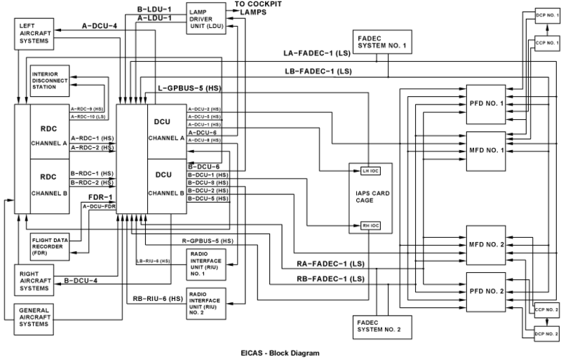
01/28/16
System Monitoring
For the DCU, there are power-up and continuous RAM and ROM tests which operate in background mode. If a failure is sensed, it is given on a diagnostic word.
Each DCU monitors all ARINC input busses for faults and inactivity. An inactive bus will be identified on the DCU diagnostic word sent to the MDC and an alternate bus used if available.
Each RDC monitors all ARINC input busses for faults and inactivity. An inactive bus will be identified on the RDC diagnostic word sent to the MDC and an alternate bus is used by the DCU, if available.
The EICAS messages that follow are related to the EICAS:
| EICAS MESSAGE(S) | LEVEL (COLOR) |
|---|---|
| PFD X-TALK FAIL | CAUTION (amber) |
| CAS MISCOMPARE | ADVISORY (cyan) |
| DCU FAULT | ADVISORY (cyan) |
| FDR FAIL | ADVISORY (cyan) |
| MFD X-TALK FAIL | ADVISORY (cyan) |
| RDC FAULT | ADVISORY (cyan) |