


Overview
The electronic flight-instrument system (EFIS) receives data from aircraft flight and navigation systems to give a visual display of many system conditions. The display control panel (DCP) and the cursor control panel (CCP) are used to make a selection of data, sensor, and display formats.
The pilot/copilot uses the reversion select panel (RSP) for selection of the reversion modes that follow:
- Displays
- Attitude/heading data source
- Air data source
- Radio tune source
- EICAS messages.
Note:
The EFIS gives data on what is shown on the display unit and where it is shown. Only general data is given in the EFIS. Data about the specific conditions and colors are given in the related sections of each system.

Adaptive Flight Display Unit
The EFIS uses four liquid-crystal adaptive flight-display (AFD) units. The display surface is 7.98 x 10.64 in (20.27 x 27.03 cm). The displays are installed on the adaptive flight-display trays found in the instrument panel. Two locks hold the AFD into position. When the locks are released, the handle can move forward and the AFD can be pulled from the tray. The AFD has also a handle at its top area which helps personnel to hold the unit during the removal/installation procedure. Two of the displays operate as the pilot primary flight-display (PFD) and the pilot multi-function display (MFD). The other two displays operate as the copilot PFD and the copilot MFD. All four of the displays are fully interchangeable. The data that follows usually shows on the PFD in normal mode:
- Aircraft pitch and roll attitude
- Compass heading
- VHF navigation system data
- Flight management system (FMS) data
- Weather radar data
- Terrain-avoidance warning system (TAWS) data
- Lightning detection data
- Flight control data
- Air data (altitude, airspeed, and vertical speed)
- Traffic alert and collision-avoidance system (TCAS) advisory data
- Auto flight annunciations
The data that follows usually shows on the MFD in normal mode:
- Engine Indication and Crew Alerting System (EICAS) data
- Radio tune data
- Aircraft systems diagrams
- Checklists
- Navigation maps
The AFDs have two parts that microprocessors control. One part receives the sensor data and prepares the data for a specified display format. The other part calculates the video data (dot patterns) that makes the display format. This part also puts the display on the AFD. The displays also have continuous self-test functions that automatically send fault data to the maintenance diagnostic computer (MDC).
The L MAIN BUS supplies 28 VDC power through circuit breaker CB1-C3 to energize the power supply in the pilot PFD. The L MAIN BUS also supplies 28 VDC power through circuit breaker CB3-F6 to energize the filament heater in the pilot PFD.
The L ESS BUS supplies 28 VDC power through circuit breaker CB1-C5 to energize the power supply in the pilot MFD. The L MAIN BUS supplies 28 VDC power through circuit breaker CB3-F7 to energize the filament heater in the pilot MFD.
The R MAIN BUS supplies 28 VDC power through circuit breaker CB2-C3 to energize the power supply in the copilot PFD. The R MAIN BUS also supplies 28 VDC power through circuit breaker CB4-F6 to energize the filament heater in the copilot PFD.
The R MAIN BUS supplies 28 VDC power through circuit breaker CB2-C5 to energize the power supply in the copilot MFD. The R MAIN BUS also supplies 28 VDC power through circuit breaker CB4-F7 to energize the filament heater in the copilot MFD.

02/04/16
Display Control Panels
The EFIS has two DCPs. The pilot DCP is installed on the glareshield on the left side and controls the pilot display units (PFD and MFD). The copilot DCP is installed on the glareshield on the right side and controls the copilot display units. Each DCP controls its on-side displays. The DCPs give an interface for the selection of display formats and sensor data.
Many of the sensor control functions are done with menu selections that show on the PFD and MFD displays. The DCPs also control radio tuning on the MFD.
When the pilot/copilot pushes the applicable menu pushbutton, the menu shows on the bottom left side of the pilot or copilot PFD. A selection box shows around the menu item that is used. Each push of the applicable menu pushbutton moves the selection box to the subsequent menu item. The menu item that is in the selection box becomes the selection that is used. When the pilot/copilot does not push the applicable menu pushbutton for five seconds, the menu automatically goes out of view. The radio menu usually shows across the bottom of the pilot MFD.
The L MAIN BUS supplies 28 VDC power through circuit breaker CB1-C4 to energize the DCP No 1. The R MAIN BUS supplies 28 VDC power through circuit breaker CB2-C4 to energize the DCP No 2.
Each DCP has 10 pushbuttons and three rotary controls. The TUNE control, MENU/DATA control, and TILT/RANGE control are found on the bottom half of the DCPs. The RADIO, BRG SRC, REFS, and RADAR pushbuttons are found in the bottom half of the DCPs. The 1/2, DME H, NAV SRC, FRMT, TFC, and TR/WX pushbuttons are found in the top half of the DCPs.
1/2
The 1/2 pushbutton does the selection of the cross-side radio menu on the MFD. When a radio submenu is in view, the equivalent cross-side radio submenu is set and canceled, when the RADIO pushbutton is pushed.
DME H
The distance measuring equipment (DME) hold function selection is set by the DME H pushbutton. When DME hold is set, the DME holds the current NAV frequency while allowing the VOR radio to be independently tuned.
The DME H and TFC pushbuttons turn the applicable functions on or off each time the pilot/copilot pushes the pushbutton. The 1/2 pushbutton interchanges the side 1 and side 2 radio data that shows on the RADIO menu.
NAV SRC
The navigation source (NAV SRC) pushbutton enables the display of a list of NAV sources on the PFD with the subsequent NAV source set. Repeated pushes of the NAV SRC pushbutton set the subsequent NAV source in the list as the new active NAV source. The NAV source list automatically times out.
FRMT
The format (FRMT) pushbutton directly sets the current PFD display format. With the displays not reverted, the format selections shall be compass rose and present position (PPOS). When displays are reverted, the resulting compressed display has format selections of compass rose, PPOS and summary. The list of available formats for selection is shown on the PFD on the left side of the lower part of the display. The FRMT pushbutton shows the summary page on a compressed PFD.
TFC
The TCAS is overlayed on the PFD's compass rose or PPOS map mode display by momentarily push the traffic (TFC) pushbutton. A second momentarily push removes the TCAS overlay.
Continuously pressing TFC for more than one second will always set the compass rose/TCAS format with the range set to the default 10 NM full range. Radar or terrain overlays, if shown before, will be removed from display.
When an resolution advisory (RA) or traffic advisory (TA) is active and TCAS is not shown, the first momentarily press of TFC will set the TCAS range to the default 10 NM. Radar or terrain overlays, if shown before, will be removed from display.
TR/WX
The terrain/weather (radar) (TR/WX) pushbutton has multiple functions. It does the selection of the terrain/weather (radar) and lightning (if installed) displays on the PFD. The first push of the pushbutton sets new condition in the TR/WX list. The PFD automatically changes the range to an applicable range if necessary. One more push of the pushbutton will move the cursor to the subsequent available condition. If the TAWS declares a terrain awareness warning or caution, a push on the TR/WX pushbutton will cause a response immediately, regardless of the current format. The first momentarily press of TR/WX will do the selection of terrain for display at its default 10 NM range and PPOS format.
The TR/WX pushbutton shows the terrain or the weather radar overlay display-format on the PFD display. The display changes from one format to the other, each time the pilot/copilot pushes the TR/WX pushbutton.
TUNE
The TUNE rotary control is used for MFD radio tune function. The TUNE control includes:
- A large outer button (coarse TUNE button)
- A small inner button (fine TUNE button)
- A pushbutton in the center (transfer pushbutton).
The coarse TUNE button is for the coarse tune control of the radio frequencies. The fine TUNE button is for the fine tune control of the radio frequencies. The transfer pushbutton is used to interchange the active frequency or channel and the recall frequency or channel. The coarse/fine TUNE buttons tune the applicable radio when the selection box is around a tune frequency or channel.
RADIO
The RADIO pushbutton, when pushed, can have two different functions in relation to the radio-menu display condition.
If the MFD radio menu is not shown, the RADIO pushbutton, when pushed, shows the MFD radio menu. The selection box goes back to the home position.
If there is not another menu or list, other than the MFD radio menu shown, and the RADIO pushbutton is pushed, the radio display that contains the selection box, expands to show the radio submenu.
BRG SRC
The bearing pointers are set from the BRG SOURCE menu on the PFD. The bearing source (BRG SRC) pushbutton shows the BRG SOURCE menu on the PFD. The selection box shows around the bearing-pointer menu used last.
MENU/DATA
The MENU/DATA control includes:
- A large outer button (MENU button)
- A small inner button (DATA button)
- A pushbutton in the center (PUSH SELECT pushbutton)
The MENU button is used to move the selection box through active menus.
The MENU button moves the selection box right and down, if turned clockwise. The MENU button moves the selection box left and up, if turned counterclockwise. The MENU button has no end stops.
The selection box moves to the left side of the MFD on the clockwise notch, after it shows in its farthest right position. The selection box moves to the right side of the MFD on the counterclockwise notch, after it shows in its farthest left position.
The MENU button moves the selection box to the necessary radio tune frequency or channel. Other than to tune the frequency or the channel, radio control is done on a radio submenu. If the selection box is not in the MFD radio menu, the MENU button moves the selection box to the necessary item.
The DATA button is used to increase a numeric value or to move the selection box.
If the selection box is around a numeric value, the DATA button increases that value, if it is turned clockwise. It decreases that value, if it is turned counterclockwise.
If the selection box is around an item that is not numeric, each clockwise DATA-button notch moves the selection box through the possible positions (right and down). Each counterclockwise notch goes through the possible selections to the left and up.
The PUSH SELECT pushbutton is used to set a value or change an item selection.
If the selection box is around a numeric value, and the numeric value is changed, then the PUSH SELECT pushbutton sets that value. The value is also set if the changed value is not adjusted for three seconds, or if the selection box moves. The selection box goes back to its home position in the MFD radio menu after 20 seconds with no adjustments. If the selection box is around an item that is not numeric, the PUSH SELECT pushbutton changes the item through its possible selections.
REFS
The barometric altitude shows in feet or in metric value. Selection of feet or metric display is done with the REFS menu. The REFS menu shows on the PFD when the reference (REFS) pushbutton is pushed. The metric indication is in a box below the English barometric altitude. An M follows the metric digits. A negative sign is before negative altitudes. All digits and the M are medium-sized.
The REFS pushbutton does the selection of menus on the PFD to set and/or activate vertical speed references, approach minimums and other selections.
RADAR
The RADAR pushbutton shows or removes the RADAR CONTROL menu from the PFD display each time the pilot/copilot pushes the pushbutton. The RADAR CONTROL menu gives mode, ground clutter suppression (GCS), gain, sector scan and target.
TILT/RANGE
The TILT/RANGE control includes:
- A large outer button (TILT rotary button)
- A small inner button (RANGE rotary button)
- A pushbutton in the center (PUSH AUTO TILT pushbutton)
The weather radar status data must show on the PFD or MFD before the RANGE/TILT/PUSH AUTO TILT control can control the radar functions.
The TILT button sets the radar antenna tilt angle. The tilt angle can be set from -15 degrees thru +15 degrees.
The RANGE button has the function to decrease or increase the PFD and MFD nav display range until the minimum or maximum range is reached. The RANGE button also controls the range of the navigation display when the PPOS display format shows on the PFD or MFD.

02/04/16
Cursor Control Panel
The CCP 1 controls the pilot MFD display and the CCP 2 controls the copilot MFD display.
The pilot/copilot uses the controls on the CCP to do the functions that follow:
- Move an FMS way point symbol on the MFD PPOS display
- Control the crew alerting system (CAS) list
- Control the checklist functions
- Control the MDC functions
- Make a selection of MFD display formats and system synoptic displays
The CCP 1 and CCP 2 are installed in the center pedestal between the pilot and copilot. The CCP 1 and CCP 2 has a joystick, menu adv/data/push select knob and 26 pushbuttons (30 pushbuttons with the 3D Map option installed).
Joystick
The joystick has eight positions and a center position (neutral). There are four positions of the joystick identified with four arrows symbols related to up, down, left and right joystick position. There are also four other positions between each arrow.
The joystick has the functions that follow:
- It moves a way point symbol on the FMS PPOS map
- It controls the lateral and vertical view angle on the 3D map (when installed)
- It moves the cursor through the checklist
- For the IFIS control, the joystick moves the zoom box and pans on charts and XM GWX (when installed)
Note:
The joystick does a selection of an item or symbol and the ENTER pushbutton, when pushed, sets that selection.
When a split window shows, the window that the joystick is active depends on the format and the selection with the JSTK button. MFD split formats where the joystick is valid are as follows:
- Checklist
- Present Position Map
- Plan map
- 3D Plan Map (option)
- Maintenance
- XM Graphical Weather degree
When the JSTK button is pushed continuously it changes the window that the joystick operates.
Orientation
When you push the orientation button for the first time, the chart rotates to 90 degrees. When you push the button again, the chart turns back to its first orientation.
CAS
When the CAS pushbutton is pushed, CAS message list shows. Each push will show the subsequent page of CAS messages.
When the last CAS message page is less than full, the CAS button causes the CAS non-warning messages to go out of view . When the CAS pushbutton is pushed again, the hidden messages come back.
CAS buttons on CCP 1 and CCP 2 (if installed) are independent of each other and control only the onside displays.
CKLST
The checklist (CKLST) pushbutton is used to show checklist items on the onside display.
SKIP
The SKIP pushbutton is used to skip checklist items on the onside display.
LWR FRMT
The LOWER FORMAT menu shows on the bottom left side of the pilot or copilot MFD when the pilot/copilot pushes the lower format (LWR FRMT) pushbutton. A selection box shows around the available display format. Each push of the LWR FRMT pushbutton moves the selection box to the subsequent format menu-item. The menu item that is in the selection box becomes the display format that is used. The format in the selection box is cyan and larger than the other display-format options. When the pilot/copilot does not push the LWR FRMT pushbutton for five seconds the LOWER FORMAT menu is automatically removed from the display.
The LOWER FORMAT menu has the display format selections that follow:
- PPOS
- Planning map (PLAN map)
- TCAS
- 3D Plan Map (optional)
- Graphical Weather (optional)
UPR FRMT
The UPPER FORMAT menu shows on the upper side of the pilot or copilot MFD when the pilot/copilot pushes the upper format (UPR FRMT) pushbutton. Summary Synoptic, Graphical Weather (optional) and OFF are the selectable formats available.
TFC
The traffic (TFC) pushbutton causes the TCAS traffic display to show. The TCAS traffic display shows on the MFD when the pilot/copilot pushes the TFC pushbutton for the PPOS map-display format . The TCAS ONLY format replaces this data when pilot/copilot pushes the TFC pushbutton for a synoptic display, FMS text, or PLAN map.
TR/WX
The TR/WX overlay display format menu shows on the bottom left side of the pilot or copilot MFD when the pilot/copilot pushes the terrain/weather (radar) (TR/WX) pushbutton. The selection procedure is the same as that for the FORMAT menu above.
The TR/WX overlay display format menu has the selections that follow:
- TR
- WX
- WX/LX
- OFF
ENTER
The ENTER pushbutton is used in conjunction with the joystick. It does the selection of the current menu item in the checklist as related to the joystick cursor position. It also enters PPOS way points as related to the joystick way point symbol position.
SUMRY
A one-page summary of the most important synoptic data shows on the display when the pilot/copilot pushes the summary (SUMRY) pushbutton. If the pilot/copilot pushes the SUMRY pushbutton again, the summary is removed from the display. If the pilot/copilot pushes a synoptic page pushbutton, the synoptic page replaces the summary page.
CHART
Push the CHART button on the CCP to show the last E-chart in view. This button is functional only when the IFIS option is installed. Selecting this button on a baseline aircraft (non IFIS) will result SELECTION INACTIVE being posted on the on-side MFD.
ESC
Each push of the Escape (ESC) button backs up one level through the menu tree. This will continue till you reach the top level on the display or, exit a displayed menu.
EICAS Synoptic Pages Selection
The flight crew can show the different synoptic pages on the lower half of MFD. The A/ICE, ECS, ELEC, FLT, FUEL, HYD, and SUMRY pushbuttons on the CCP 1 or CCP 2 show these pages on onside displays when pilot/copilot pushes applicable pushbuttons. Only one synoptic page can show on the display at one time.
With the introduction of the MENU ADV/DATA PUSH SELECT knob, a new functionality known as the Step function is introduced. The Step function allows the pilot to scroll through the synoptic pages when a synoptic page is displayed in the Lower Window. Turning either the MENU ADV or DATA knob clockwise, or pressing the PUSH SELECT button will display the next synoptic in the following sequence: A/ICE, ECS, ELEC, FLT, FUEL, HYD, SUMRY and then wrap to the first synoptic. Turning the MENU ADV or DATA knob counter-clockwise will display synoptics in the reverse sequential order.
A/ICE
The A/ICE button shows the ANTI-ICE synoptic page.
ECS
The ECS button shows the environmental control system synoptic page.
ELEC
The ELEC button shows the ELECTRICAL synoptic page.
FLT
The FLT button shows the FLIGHT CONTROLS synoptic page.
FUEL
The FUEL button shows the FUEL synoptic page.
HYD
The HYD button shows the HYDRAULIC synoptic page.
Checklist Controls / Display / Selection
The checklist display can show on the top half of the pilot/copilot MFD when the pilot/copilot pushes the CKLST pushbutton. The joystick moves the cursor on the checklist index and checklist menu pages. The pilot/copilot uses the ENTER pushbutton for selection of a checklist from the checklist index page. Check marks show to the left of each checklist menu item while the cursor moves down the checklist. If the pilot/copilot pushes the SKIP pushbutton, the checklist menu item does not get a check mark. The pilot/copilot pushes the CKLST pushbutton a second time to remove the checklist display.
Maintenance Diagnostic System Data
The maintenance diagnostic system data shows on the MFD if the pilot/copilot pushes the A/ICE,ECS, and FUEL pushbuttons at the same time. The flight-control system diagnostic-data shows on the MFD if the pilot/copilot pushes the A/ICE, ECS,and FLT pushbuttons at the same time.
If a diagnostic mode is on, the CCP 1 or CCP 2 controls the following change functions to control the diagnostic displays:
- Joystick
- LWR FRMT pushbutton
- TFC pushbutton
- TR/WX pushbutton
- ENTER pushbutton
When the MFD is not in a diagnostic mode or shows a checklist display, the pilot/copilot can use the joystick to show a way point location on a PLAN map. The pilot/copilot moves the + cursor to the way point location on the map using joystick and then pushes the ENTER pushbutton. This causes the display to send the latitude and longitude data back to the flight management computer to give the location of the way point.
The geographic co-ordinate also shows on the CDU scratch pad.
UPR MENU
The Upper Menu button shows or remove an upper menu. The content of the menu is based on the format.
This button is functional only when the IFIS option is installed.
LWR MENU
The Lower Menu button shows or remove a lower menu. The content of the menu is based on the format.
This button is functional only when the IFIS option is installed.
STAT
The Status button shows a menu of some MFD formats. The status menu shows when a status format window is selected on the MFD and the CCP UPR or LWR MENU button is pushed.
The STAT menu can include the formats that follow:
- Database Effectivity
- Chart Subscription
- File Server Configuration
This button is functional only when the IFIS option is installed.
MENU ADV
The Menu Advance knob is used to set the menu cursor around the necessary shortcut, menu item, or alphanumeric entry field. The clockwise turn of the knob moves the cursor down the page. The counterclockwise turn moves the cursor up the page. This knob is also for synoptic control.
DATA
The DATA knob is used to move forward through the characters and counterclockwise to move through the characters when the data entry mode is ON. It is used, with a chart in view, to browse through the list of connected charts associated with the airport identified by the chart shown.
PUSH SELECT
This button selects the item highlighted by the menu cursor. This button is also used for synoptic control.
MEM1, MEM2, MEM3
Three Memory (MEM1, 2 and 3) quick access buttons are used to save, then recall display format configurations for the MFD. Only combinations of split-display formats, such as the Checklist and the PPOS Map are saved. To keep the present MFD values/conditions in storage, push one of the three quick access buttons for more than three seconds. The upper format, lower format, TR/WX overlay condition, and TFC overlay conditions are saved.The messages that follow are available for the display on the MFD when a save is requested:
- CANNOT STORE shows when a memory button is released and a full format or an excluded split format shows.
- STORE shows when a quick access button is pushed for more than 3 seconds and the QAK STORE is unlocked. This message indicates to the pilot that the button should be released to complete the STORE action.
- STORE COMPLETE shows when a quick access button is released and the present MFD display parameters are saved successfully.
- STORE LOCKED shows when a memory button is pressed for more than 3 seconds while the QAK STORE is locked.
When one of the quick access buttons on the CCP is pushed and released in less than 3 seconds a recall is shown. When the buttons are pushed to recall a set of formats the applicable split view (upper and lower formats) replaces the full formats that are presently in view. The messages that follow are available for the display on the MFD when a recall is requested:
- RECALL COMPLETE shows on the MFD when the recall action is complete.
- RECALL UNAVAIL shows on the MFD when the system tries to recall a set of MFD display parameters and fails to recall because of a fault.
ZOOM (+/-)
When a new chart is selected, it is initially scaled until the width of the chart fills the display. When the chart is turned to landscape, the chart is scaled again to let the height of the chart to fill the display window. Operate the joystick to move the pan/zoom window to the area of the chart until it can be zoomed. The first push of the ZOOM button increases the dimension of the area set before in the pan/zoom window. The second push of the ZOOM button makes the chart to come to the full scale. This button is functional only when the IFIS option is installed.

Checklist/Line Advance Switch
The checklist/line advance switch is found on the two control wheels. The checklist display can only show on the copilot MFD. The checklist/line advance switch does one function, it moves the cursor down on the checklist index and checklist menu pages. Check marks show to the left of each checklist menu item while the cursor moves down the checklist. The switch does the equivalent function of the CCP joystick moved in the down position. The switch selection signal is sent to the DCP.

Reversion Select Panel
The RSP is installed in the center pedestal between the pilot and copilot.
The RSP has six rotary switches that control the selection of reversion modes.
Left Displays Switch
The LEFT DISPLAYS switch controls the reversion function for the two AFDs on the pilot side. In the NORM position, the pilot left display operates as a PFD and the pilot right display operates as an MFD. In the PFD REV position, the right display de-energizes, and the left display operates as a PFD that has a compressed display format. The compressed display format shows all the usual PFD data, with the EICAS data, and system diagrams from the pilot MFD. In the MFD REV position, the left display de-energizes, and the right display operates as a PFD and has a compressed display format.
Tune Switch
The TUNE switch controls selection of the radio tune source. In the NORM position, the pilot controls the radios. He can use the radio tune menu on the pilot/copilot MFD, or he can use the control display unit (CDU). In this configuration, the CDU tunes the radios through the MFD.
In the MFD ONLY position, the pilot/copilot tunes the radios with the MFD radio-tune menu.
In the CDU ONLY position, the CDU tunes the radios directly. The MFD radio tune menu goes out of view in this configuration.
In the COM1 121.5 position, the COM1 radio tunes to the 121.5 MHz emergency frequency. Other radios can be tuned with the MFD or the CDU.
Right Displays Switch
The RIGHT DISPLAYS switch controls the reversion function for the two AFDs on the copilot side. In the NORM position, the copilot right display operates as a PFD and the copilot left display operates as an MFD. In the PFD REV position, the left display de-energizes, and the right display operates as a PFD that has a compressed display format. The compressed display format shows all the usual PFD data, with the EICAS data, and system diagrams from the pilot MFD. In the MFD REV position, the right display de-energizes,and the left display operates as a PFD and has a compressed display format.
ATT/HDG Switch
The attitude/heading (ATT/HDG) switch controls the selection of the attitude/heading data source. In the NORM position, each side (pilot and copilot) receives attitude/heading data from its on-side attitude/heading data source. When the ATT/HDG switch is in position 1, the No. 2 attitude/heading data source de-energizes, and the No. 1 attitude/heading data source supplies data to the pilot and copilot displays. When the ATT/HDG switch is in position 2, the No. 1 attitude/heading data source de-energizes, and the No. 2 attitude/heading data source supplies data to the pilot and copilot displays.
AIR DATA Switch
The AIR DATA switch controls the selection of the air data source. In the NORM position, each side (pilot and copilot) receives air data from its on-side air data source. When the AIR DATA switch is in position 1, the No. 2 air data source de-energizes, and the No. 1 air data source supplies air data to the pilot and copilot displays. When the AIR DATA switch is in position 2, the No. 1 air data source de-energizes, and the No. 2 air data source supplies air data to the pilot and copilot displays.
EICAS Switch
The EICAS switch controls the selection of the EICAS messages display on the pilot MFD, in the copilot MFD or on the two PFDs.
When the switch is in BOTH PFDS position, the left and right PFDs show the compressed format.
When the switch is in L MFD position, the pilot MFD shows the EICAS messages.
When the switch is in R MFD position, the copilot MFD shows the EICAS messages.

Adaptive Flight-Display Tray
The adaptive flight-display trays are installed in the instrument panel. The function of the trays are to hold and lock the AFDs. The AFDs are locked in position with locks found on the front of the AFDs. There are no electrical connectors on the trays.

06/12/17
System Operation
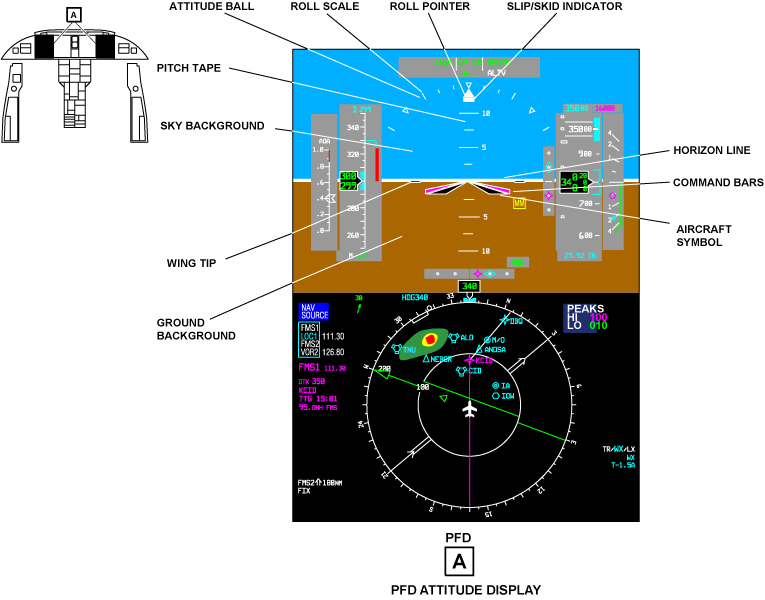
PFD Attitude Displays
The attitude display shows the aircraft pitch and roll attitude in relation to the horizon. The components that follow are part of the attitude display:
Sky/Ground Background
The attitude display uses an attitude ball to show the sky and ground position in relation to the aircraft. The blue part of the attitude ball is the sky and the brown part is the ground.
Aircraft Symbol
The black V-shaped symbol at the middle of the attitude display shows the aircraft symbol. The aircraft symbol has a white contour.
Command Bars
The wing-shaped symbols at the outer edges of the aircraft symbol are the command bars. This type of command bar is also known as V-bars. The command bars show on the PFD only when EFIS operates in flight director mode. Flight guidance commands cause the command bars to move up and down in relation to the aircraft symbol. This gives pitch steer commands to the pilot. The command bars also make a left and right bank to give roll commands.
To use the V-bar steer commands, the pilot controls the aircraft symbol to move into the apex of the V formed by the command bars. The command bars align with the edges of the aircraft symbol when the aircraft is on course.
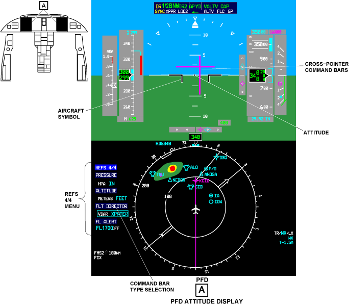
The pilot and copilot can independently change the command bar type that shows on their PFD. To do this, they use the FLT DIRECTOR selection on the REFS 3/3 menu at the left of the compass rose. The V-bar is the usual type of command bar. The other type of command bar is the cross-pointer. When the display uses cross-pointers to show steer commands, the horizontal pointer gives the pitch steer commands and the vertical pointer gives the roll steer commands.
With the selection of cross-pointers, a small square shows at the middle location of the attitude display. The aircraft symbol also changes to a divided T-shaped symbol. To use the cross pointer steer commands, the pilot controls the aircraft and aircraft symbol to move in the direction of the cross pointer intersection.
Pitch Tape
The white marks and numbers on the attitude ball display are the pitch tape. The pitch tape moves up and down in relation to the stationary aircraft symbol to show aircraft pitch angle. The aircraft pitch angle shows in 2.5 degrees increments on the pitch tape from 0 to 20 degrees up or down. From 20 to 30 degrees up and down, the pitch angle shows in 5 degrees increments on the pitch tape. For more than 30 degrees up and down, the pitch angle shows in 10 degrees increments on the pitch tape. The pilot/copilot read the aircraft pitch angle from the pitch tape at the top of the aircraft symbol.
Horizon Line
The white line between the sky and the ground is the horizon. The horizon line is the 0 degree pitch reference. It moves out of view when the aircraft pitch angle is more than 18 degrees (up or down).
Wing Tips
The wing tips are black and have a white contour. They are set at the 3 o'clock and 9 o'clock positions of the attitude ball display. When the white horizon line aligns with the wing tips, the aircraft pitch and roll attitude are each at 0 degree.
Roll Pointer
The attitude ball display (pitch tape and horizon line) turns around the top of the aircraft symbol to show the aircraft bank angle (roll attitude). The solid white triangle at the top of the attitude ball display is the roll pointer. It moves with the attitude ball display and points to the bank angle indication on the roll scale.
Roll Scale
The roll scale is the arc-shaped scale above the attitude ball display. It has small white triangles and thick marks to show bank angles of 0, 10, 20, 30, 45, and 60 degrees. The small white triangles show the 0 degree position and the 45 degrees bank angles on each side of 0 degree position. The short thick marks show the 10 and 20 degrees bank angles on each side of the 0 degree. The long thick marks show the 30 and 60 degrees bank angles on each side of 0 degree.
Slip/Skid Indicator
The white rectangular symbol at the bottom of the roll pointer is the slip/skid indicator. The rectangle moves laterally from the roll pointer to show lateral acceleration. The displacement of one rectangle width is equal to a one ball displacement of a standard inclinometer.
Unusual Attitude Display
The PFD changes to an unusual attitude display when the aircraft pitch or roll pitch becomes too large. A pitch-up pitch attitude more than +30 degrees or a pitch down angle more than -20 degrees is too large. Red chevrons show on the pitch tape to give a warning of a pitch angle that is too large. A left or right bank-roll attitude more than +65 degrees is too large.
During unusual attitude operation, EFIS removes all display data and annunciators that are not necessary from the PFD. This gives a better view of an unusual attitude condition, so that the pilot/copilot sees and corrects the condition immediately. EFIS also ignores all inputs from control panels during unusual attitude operation.
The data and annunciators that follow are not removed from the PFD during unusual attitude operation:
- CAS cautions and warnings
- Engine data
- Attitude
- Airspeed
- Trend vector
- Yaw damper (YD) disengage
- Autopilot (AP) engage/disengage
- Angle-of-attack (AOA) annunciators
When the pilot corrects an unusual attitude condition, all attitude data and annunciators show again on the PFD. The aircraft pitch and roll angles must be as follows for the PFD to go back to the normal mode of operation:
- The roll angle must be equal or less than +60 degrees (left or right)
- The pitch down angle must be equal or less than -15 degrees
- The pitch up angle must be equal or less than +25 degrees
Attitude Flag
If an attitude data failure occurs, EFIS removes the attitude ball display (pitch tape, roll scale, and horizon line). The attitude flag (a red boxed ATT) shows above the aircraft symbol. It flashes for the first 5 seconds and then stays on.
An attitude data failure occurs for the reasons that follow:
- The ARINC 429 pitch and/or roll data words are missing
- The signal status matrix (SSM) bits show failure status
- The SSM bits show no computed data (NCD)
Flight Director Flag
The flight director flag (a red boxed FD) will show in the top left part of the attitude ball display if any of the failures that follow occur:
- A flight guidance computer (FGC) failure occurs
- A sensor that the FGC uses fails
- The PFD does not receive fight guidance data for two or four seconds
- The SSM bits give a fail or NCD indication
Attitude Source
EFIS automatically uses the on-side attitude/heading system (AHS) for each PFD. This is true unless the ATT/HDG switch (on the RSP) is set to a reversion position (1 or 2). The PFD does not show an AHS annunciation when the on-side AHS is used. If the PFD uses the cross-side AHS, a yellow AHS1 or AHS2 annunciation shows in the top right corner of the PFD in the same place. This is to the right of the vertical speed display.
When the aircraft is on the ground and the AHS is in align mode, the message ATT/HDG ALIGNING DO NOT TAXI shows in white above the aircraft symbol. If the aircraft is airborne and the AHS is in align mode, the message ATT/HDG ALIGNING shows in white above the aircraft symbol.
Attitude Comparator
EFIS compares the pitch and roll angles of the pilot PFD to pitch and roll angles of the copilot PFD. The attitude comparator flag (a yellow boxed ATT, PIT, or ROL) can show on the PFD. It shows immediately above the right 45 degrees roll-mark (the right triangle of the roll scale) for the conditions that follow:
- There is a pitch or roll difference of more than 4 degrees between sides (pilot and copilot PFDs) and there is no glideslope locked condition
- There is a difference of more than 3 degrees between sides and there is a glideslope locked condition
The yellow boxed ATT flag shows when the pitch and roll comparators are incorrect. The yellow boxed PIT flag only shows when the pitch comparator is in error. The yellow boxed ROL flag shows when only the roll comparator is in error.

PFD Heading Display
The aircraft heading display shows on the bottom half of the PFD below the attitude ball display. The components that follow are part of the heading display.
- Format menu
- Compass rose
- PPOS map
- Aircraft symbol
- Lubber line
- Aircraft digital heading readout
- Heading bug
- Digital selected heading readout
- Heading source annunciation
- HDG flag
- HDG comparator flag
- Heading display in compressed PFD
The bottom half of the PFD usually shows one of two displays. It shows a standard compass rose display, or a compass rose display with a PPOS map overlay display format. These two displays show below the attitude ball. The pilot/copilot uses the FORMAT menu for selection of the display format.
Format Menu
The FORMAT menu shows on the bottom left side of the PFD when the pilot/copilot pushes the FRMT pushbutton on the DCP. Usually there are only two selections on the FORMAT menu, ROSE and PPOS. The selection box is around all the menu items. Each push of the FRMT pushbutton sets the subsequent menu item on the FORMAT menu. The set menu item is cyan and larger than the other menu items. The FORMAT menu is removed from PFD after five seconds if the pilot/copilot does not push the FRMT pushbutton again.
When one or the two EFIS displays operate in reversion mode, a SUMMARY selection also shows on the FORMAT menu. This display format shows a one-page summary of the most important synoptic data.
Compass Rose
The selection of a navigation source (manual or automatic), other than an FMS, causes the FMS flight plan symbols to go out of view. The standard compass rose display shows.
The ROSE selection shows the compass rose display with the standard course arrow and course deviation bar display. The compass rose is usually a full 360 degrees display, but it can change to a 300 degrees rose if the EFIS displays operate in reversion mode. All types of navigation source data can show on the compass rose display format.
The letters N, S, E, and W show the positions of the four cardinal points on the compass rose. The long indices around the compass rose show the 10 degrees points (10, 20, 30, thru 360). The short indices around the compass rose show the 5 degrees point (5, 15, 25, thru 355). The cardinal points and indices that show on the compass rose move with the compass rose display.
The compass rose display has stationary reference marks external to the compass rose at the points that follow:
- 360 degrees
- 45 degrees
- 90 degrees
- 135 degrees
- 180 degrees
- 225 degrees
- 270 degrees
- 315 degrees
The reference marks at 45, 135, 225, and 315 degrees are small white triangles that point to the compass rose. The reference marks at 360, 90, 180, and 270 degrees are short white lines.
PPOS Map
The PPOS map format can show an FMS flight plan if an appropriate flight plan is set. The PPOS map shows the navigation aids, way points, and legs of the flight plan. The map moves in relation to the aircraft symbol at the middle of the display. The pilot/copilot controls the range (radius around the aircraft symbol) of the map with the RANGE button on the DCP. The range of the map shows in the compass rose at the 10 o'clock position.
Aircraft Symbol
The stationary aircraft symbol at the middle of the compass rose display shows as a stick aircraft. The stationary aircraft symbol at the middle of the PPOS map display shows as an aircraft outline.
Lubber Line
The lubber line is the gray stationary pointer symbol around the aircraft digital heading display. The aircraft heading is read from the compass rose at the point of the lubber line.
Aircraft Digital Heading Readout
A green 3-digit display at the 12 o'clock position, immediately above the compass rose, shows the aircraft heading. The aircraft digital heading display can show magnetic, true (TRUE), or directional gyro (DG) heading.
The heading reference system supplies magnetic heading data when the HEADING pushbutton is out. The heading reference system supplies DG heading data when the HEADING pushbutton is pushed in. During DG operation, the pilot/copilot uses the SLEW switch on the COMPASS control panel to correct the aircraft heading for gyro drift. A selection of TRUE heading data occurs automatically when the FMS is used as the navigation source.
Heading Bug
The heading bug (HDG bug), when set, is a cyan symbol that shows as two small rectangles with a space between them. The pilot/copilot turns the HDG button on the FGP to set the position of the HDG bug on the compass rose. If the pilot/copilot pushes the SYNC button on the FGP, the HDG bug moves immediately to the aircraft heading (the 12 o'clock position on the compass rose below the lubber line).
When the PFD uses the 300 degrees compass rose display format, the HDG bug can go out of view at the bottom of the compass rose. When this condition occurs, a heading vector line (a dashed line from the compass middle to the HDG bug) shows the out of view position of the HDG bug.
Digital Selected Heading Readout
A cyan-colored 3-digit display shows the set heading as the pilot/copilot turns the HDG button. This display gives the digital position of the set heading bug display as it is set. The set heading readout shows to the left of the aircraft digital heading readout. The selected heading readout is removed from the PFD five seconds after the HDG bug is set.
The automatic flight-control system (AFCS) uses the selected heading as a reference value when it operates in heading hold mode. The selected heading readout shows on the PFD continuously when the AFCS uses heading hold mode.
Heading Source Annunciation
The heading source annunciation shows above and to the right of the digital heading display. It gives the heading data type. A cyan DG annunciation shows when the heading reference system operates in directional gyro mode.
HDG Flag
If a heading data failure occurs, the compass display turns to a north-up position and the lubber line is removed from the PFD. A HDG flag (a red boxed HDG) replaces the aircraft digital heading display on the PFD. The HDG flag flashes for the first five seconds and then stays on.
A heading data failure occurs for the reasons that follow:
- The ARINC 429 heading data word is missing
- The SSM bits show failure status
- The SSM bits show NCD.
HDG Comparator Flag
EFIS compares the heading data from the pilot and copilot PFDs. The heading comparator flag (a yellow boxed HDG) replaces the digital set heading display of the PFD. It does this if there is a heading difference of more than 6 deg.


Heading Display in Compressed PFD
When a PFD operates in reversion mode, the PFD changes to a compressed display format. In this format, the compass tape display, and synoptic summary display replace the compass rose display (or PPOS display format if shown). The heading marks, HDG bug, heading readout, and lubber line of the compass tape are the same as those on the compass rose. The compass tape display shows only 50 degrees of heading on each side of the lubber line. The compass tape moves from right to left to show clockwise movement of a compass rose.

PFD Navigation Display
The displays and annunciations that follow are components of the navigation displays:
Navigation Source Menu
A NAV SOURCE menu shows on the middle left side of the PFD when the pilot/copilot pushes the NAV/SRC pushbutton on the DCP. The active navigation source shows on the menu with larger cyan letters. The other navigation source selections show with smaller white letters. Each push of the NAV/SRC pushbutton makes the subsequent navigation source on the menu cyan and larger than the other sources. The NAV SOURCE menu is removed from the PFD for the causes that follow:
- The pilot/copilot does not push the NAV/SRC pushbutton for five seconds or more
- Selection of a different menu
- The pilot/copilot tunes the radios from the MFD
Note:
The MENU, DATA, and PUSH SELECT controls on the DCP are not on when the NAV SOURCE list shows on the PFD. The message SELECTION INACTIVE shows in the bottom right corner of the PFD if the pilot/copilot uses one of these controls during this time.
Active Navigation Source Data
The active navigation source and applicable data show in an annunciation field below and to the left of the airspeed display. This is at the 10 o'clock position in relation to the compass rose.
Navigation Source
The first line of the active navigation source data identifies the navigation source (VOR1, VOR2, LOC1, LOC2, FMS1, FMS2, or FMS). If the navigation source is the on-side VOR or LOC, its color is green. If the navigation source is the cross-side VOR or LOC, its color is yellow. When VOR and LOC source data is correct, the station frequency shows in the same color to the right of the navigation source identifier. If the navigation source is FMS, FMS1, or FMS2 its color is magenta. When the EFIS energizes, it uses the last navigation source that was set when it was last operated.
Course/Desired Track
The second line of the active navigation source data identifies the course/desired track selection. A 3-digit course or track value shows to the right of the course/desired track identifier. The course/desired track identifiers that follow can show on the second line of the active navigation source data display:
- CRS (for VOR or LOC)
- B/C (for LOC back course)
- DTK (for FMS)
- HDG (for FMS)
The FMS controls the selection of HDG or DTK. If the navigation source is VOR, the course/desired track identifier is CRS. If the navigation source is LOC, then the course/desired track identifier is also CRS. But it is only CRS if the aircraft heading is also equal to or less than 110 degrees from the set course/desired track pointer. If the aircraft heading is more than 110 degrees from the course/desired track pointer setting, the course/desired track identifier is B/C.
If FMS HDG or DTK data becomes incorrect, the digital course/desired track value changes to dashes (---). If CRS or B/C data becomes incorrect, the digital course/desired track value stays at its last correct value.
Active Station or Way Point Identifier
The third line of the active navigation source data shows the active station or way point identifier. The identifier can have a maximum of seven letters/digits.
TTG
The fourth line of the active navigation source data shows TTG (time-to-go) with the time (in minutes and seconds) to the station or way point. The time is removed (not the TTG legend) if the TTG data word is not there or the TTG data word SSM bits give a fail indication. The time shows as --.-- if the TTG data word SSM bits give a NCD condition.
Distance to Active Station, Way Point or Runway
The fifth line of the active navigation source data shows the distance to the active station, way point, or runway (if LOC). If the navigation source is VOR or LOC, distances of 0 thru 512 NM can show. The resolution is 0.1 NM for distances of 0 thru 99.9 NM and 1 NM for distances of 100 thru 512 NM. The letter H shows after the distance value (in place of the NM) with the selection of DME hold mode. The selection of DME hold also removes the station identifier (third line of the active navigation source data).
If the navigation source is FMS, distances of 0 thru 9999 NM can show. Dashes (----) show in place of the FMS distance when the value is more than 9999.
Course/Desired Track Pointer
The course/desired track pointer is a solid bar and triangle-head pointer that extends across the diameter of the compass rose. The course/desired track pointer is the same color as the active navigation source. The pilot/copilot turns the CRS button on the FGP to set the course or necessary track. This moves the course/desired track pointer on the compass rose. It also changes the digital course/desired track display to the same value (shows to the right of the course/desired track identifier). When the active navigation source is a VOR, the pilot/copilot can set a course directly to the station with the PUSH DIRECT button on the FGP. The course/desired track pointer and digital display are set to the station bearing when this button is pushed.
The course/desired track pointer does not show on the PPOS display format (FMS navigation source).
Lateral/Cross-Track Deviation Bar
The middle part of the course/desired track pointer is the lateral/cross-track deviation bar. It moves at a 90 degrees angle in relation to the head and the tail of the course/desired track pointer. The lateral/cross-track deviation bar shows the position of the course or desired track in relation to the aircraft.
Lateral/Cross-Track Deviation Scale
The lateral/cross-track deviation scale has four white dots (two on each side of the aircraft symbol). The lateral/cross-track deviation scale is always perpendicular to the lateral/cross-track deviation bar (thus it turns with the course/desired track pointer). The quantity of lateral/cross-track deviation is read from the lateral/cross-track deviation scale.
The lateral/cross-track deviation scale does not show on the PPOS display format (FMS navigation source).
Lateral Deviation Pointer and Scale
A lateral deviation pointer and scale display show on the PFD between the attitude ball and compass rose display when the navigation source selection is LOC. The scale has four dots and a middle thick mark that are gray. The localizer pointer is diamond-shaped and is same color as the navigation source. This display shows lateral deviation from the localizer course (runway). When the pointer deviation goes off of the scale, only half of the pointer symbol shows. The pointer movement changes to the opposite direction when the PFD senses the localizer back course (the aircraft heading is more than 100 degrees from the lateral/cross-track pointer position).
The lateral deviation pointer and scale display (between the attitude ball and compass 110 degrees display) also show on the PFD for FMS navigation sources. They show when the bottom display format selection is PPOS and aircraft heading is less than 100 degrees from the lateral/cross-track pointer position. The lateral deviation pointer is star-shaped (way point symbol) for FMS lateral deviation display.
If the AGL (above ground level) altitude is 600 ft (182.88 m) or less, and the DH (decision height) is set to less than 200 ft (60.96 m), the PFD senses a category 2 approach. An expanded localizer deviation scale replaces the lateral/cross-track deviation scale (between the attitude ball and compass displays) for a category 2 approach. The expanded localizer deviation scale has two squares (for dots) and a middle thick mark that are gray.
Vertical Deviation Pointer and Scale
The vertical deviation pointer and scale show on the PFD between the attitude ball and altitude displays. They show when the active navigation source is LOC and the aircraft heading is less than 100 degrees from the lateral/cross-track pointer position. The vertical scale has two gray dots above and below the middle thick mark. The glideslope pointer is diamond-shaped and is the same color as the navigation source. The vertical deviation pointer and scale are removed from the display when the aircraft heading is more than 110 degrees to the lateral/cross-track pointer.
The vertical deviation pointer and scale also show on the PFD when an active FMS navigation source gives vertical navigation (VNAV) commands. The FMS vertical deviation pointer is magenta and star-shaped (way point symbol) for FMS vertical deviation display.
To/From Pointer
The to/from pointer is a small triangle (the same color as the active navigation source). It shows below the lateral/cross-track deviation pointer (the course/desired track pointer goes through the to/from pointer). The aircraft flight path is to the active VOR or FMS way point when the triangle points to the head of the course/desired track pointer. The aircraft flight path is from the active VOR when the triangle points to the tail of the course/desired track pointer. The pointer does not point from an active FMS way point. The to/from pointer does not show on the PFD when the active navigation source is LOC.
The to/from pointer does not show on the PPOS display format (FMS navigation source).
Drift Track Pointer
The drift track pointer is a green open circle-shaped pointer that shows on the compass rose, heading tape, and PPOS displays. The FMS calculates the aircraft track in relation to the aircraft heading. The angle between the track pointer and the aircraft heading (lubber line) shows the drift angle. When the tracker pointer is below the lubber line the aircraft is on track. The FMS supplies track data to the PFD when the FMS is energized. The selection of the FMS as the navigation source is not necessary. If the track pointer data becomes incorrect, or there is a heading display failure, the track pointer is removed.
Wind Speed/Direction Display
The FMS also supplies wind speed and direction to the PFD. An FMS navigation source is not necessary. A green arrow, to the left of the navigation source data, shows the direction of the wind in relation to the aircraft. A three digit display (also green) above the arrow shows wind speeds from 5 thru 255 kts. The wind speed and direction display is removed for the causes that follow:
- The wind speed is less than 5 kts or more than 255 kts
- The wind speed data becomes inapplicable
Preselect Navigation Source
The preselect navigation source and frequency show below the active navigation source data. This data show in cyan.
Preselect Course Pointer
The preselect course pointer is a cyan, dashed double bar. It can be seen when the active course pointer is in view. It can be seen even if the active and preselect course pointers are aligned.
Preselect Lateral Deviation Bar
The preselect lateral deviation bar is the center portion of the preselect course pointer. The bar moves left or right of the preselect course pointer to show aircraft position relative to the preselect course. It can be seen even if the active and preselect course pointers are aligned. The preselect lateral deviation bar uses the lateral/cross-track deviation scale.
Aircraft Symbol
The shape of the aircraft symbol, at the middle of the compass, changes with display format (ROSE or PPOS) and the navigation source. The aircraft symbol is a stick aircraft when the display format is ROSE (this is correct for all navigation sources). The aircraft symbol is the outline of an aircraft when the display format is PPOS (FMS navigation source only).
FMS annunciation Message
The PFD can show the NO FLIGHT PLAN annunciation on the PFD above aircraft symbol. It shows when the FMS that is set as the lateral navigation source has no active flight plan.
The PFD can show the DISCONTINUITY annunciation above aircraft symbol. It shows when the active leg of the flight is a discontinuity.

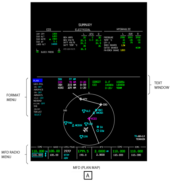
MFD Navigation Display
The CCP 1 or the CCP 2 LWR FRMT push button sets the type of display from the FORMAT menu, for the bottom part of that MFD. The CCP 1 or the CCP 2 can show the PPOS map, the PLAN map, the 3D MAP option (if installed) and the TCAS format types of displays. The CDU can show the FMS text only on its display (MFD DATA).
Format Menu
The first push of the LWR FRMT push button shows the FORMAT menu. The selection box is around all available display types. The LWR FRMT push button moves the selection to the subsequent available display type. A format that is not available will not show, and the message FORMAT NOT AVAILABLE is shown. The PLAN map is not available if the PFD shows a PPOS map when FMS is the navigation source. FMS text is not available if the PFD shows a PPOS map and FMS is the navigation source. TCAS is available when TCAS is installed.
The Upper Format (UPR FRMT) button selects the display format of the upper portion of the MFD. UPR FRMT selectable formats available are Summary Synoptic, Graphical Weather (optional), and Off.
When the aircraft energizes, the MFD FORMAT that was set before the aircraft de-energized shows on the MFD. If there is no input from the PFD, data usually controlled by the PFD will be shown on the MFD. It will be read from non-volatile memory and shown. The MENU, DATA and PUSH SELECT buttons do not operate when the FORMAT menu is shown. The FORMAT menu goes out of view when one of the actions that follows occurs:
- Another list or menu push button is pushed
- FMS text only display type is shown
- An aircraft systems display is shown
- A radio is tuned
PPOS Map
The MFD PPOS map is almost the same as the PFD PPOS map. The bearing pointers shown on the MFD are the same as the bearing pointers set on the PFD. The CDU FMS controls can show the three PPOS map display formats that follow:
- No data window, no extended map
- Data window shown
- Extended map shown
The second two formats can only show on the MFD. The area on the MFD above the PPOS map or the PLAN map is for some text or an extended map. This area is the text window. The FMS that is the NAV source controls the dimension, color, and location of alphanumeric symbols in the text window.
The FMS text window shows a maximum of four lines of FMS text data above the PPOS map in the data window format. The FMS supplies the text in ASCII format. The FMS text window usually contains data for a flight leg. An FMS is the map source.
The extended PPOS map shows approximately 50% more forward range. The MFD text window shows the extended PPOS map in the extended PPOS map format. When it shows the extended PPOS map, it does not show the FMS text window.
The PPOS format will show on the PFD and the MFD when the conditions that follow occur:
- If in FMS text only format
- If the DCP FRMT pushbutton shows the PPOS format display
- If the NAV source is an FMS
The PPOS format will show with overlays set before.

PLAN Map
The PLAN map is a navigation map. The plan map shows FMS flight plans. The plan map display has three formats:
- No data window, no extended map
- Data window shown
- Extended map shown.
The extension on the PLAN map is always to the North. The FMS sets a latitude and longitude that becomes the center of the map. The map radius is set with the RANGE button on the DCP. There is a maximum of 2s delay after the PLAN map controls are operated, before the AFD shows the new PLAN map. Input from the FMS puts the aircraft symbol at a position on the map. The IRS input turns the aircraft symbol.
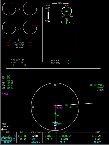
3D Map (Post SB 350-34-003)
The optional 3D Map is an FMS feature that provides horizontal, vertical, and performance predicted flight plan information in a single, combined Three Dimensional (3D) format on the MFD. The map data is a combination of what would typically be shown as two separate map formats; a vertical profile and a plan map.
The 3D Map has an adjustable viewing orientation that allows the pilot to customize the viewing angle that is desired. In addition to the traditional map controls for range and map center, view controls on the Cursor Control Panel (CCP) and MFD provide for rotation of the map presentation about two axes. The two axes of rotation are:
- A line through the map center that is parallel to the vertical plan of the display, which allows various perspectives of vertical views.
- A line through the map center that is perpendicular to the horizontal plane of the map center, which allows various perspectives of horizontal views.
The 3D Map allows predicted flight path views that are referenced from the ground (for example, the vertical profile view), referenced directly over a map center position (for example, the PLAN MAP view), or referenced from an intermediate point in between.
The 3D Map controls provide for manual control of the viewing modes and preset viewing angles. Manual control allows the pilot to set the view to any desired angle within the available limits. Preset views allow the pilot to select fixed viewing modes with minimal workload. An automatic view control maintains the desired viewing angle regardless of the current heading of the aircraft. Controls for the 3D Map are located on the CCP.
The LWR FRMT button on the CCP shows the next available MFD lower format. When the selected MFD format is 3D PLAN, the manual, preset, and automatic view controls for the 3D Map are active. Push the LWR MENU button to bring up the 3D PLAN sub-menu. The sub-menu selections include TOP - (ON), SIDE - (L,R), SHLDR - (L, C, R), and AUTO VIEW (ON, OFF). Use the MENU ADV knob to move the cyan selection box to the desired view and push the PUSH SELECT to select. Use the DATA knob for individual selections within the sub-menu (for example, SHLDR – L, C, R). The CCP joystick is used to manually set the horizontal and vertical viewing angles.
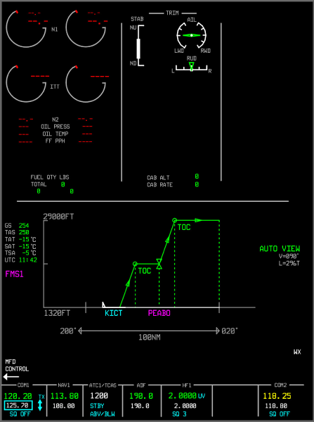
TOP View
Select TOP view from the 3D PLAN sub-menu. The TOP view is the standard plan map look-down viewing angle with minimal vertical flight plan information.
SIDE View
Select SIDE view from the 3D PLAN Map sub-menu using the CCP controls. The side view is the vertical profile display with minimal horizontal flight plan information.
Selecting the side view changes the 3D PLAN Map presentation to a 90 degree horizontal and 90 degree vertical viewing angle relative to the inbound course of the map center waypoint at the time of the selection. The side view provides a full vertical view with a horizontal viewing angle that is perpendicular to the inbound course of the map center waypoint. The 90 degree horizontal angle can be left or right of the inbound course depending on the direction of rotation of that provides the smallest amount of angular change to the 3D PLAN Map presentation. When SIDE is selected, use the DATA knob on the CCP to alternate the view 90 degrees left and right of the inbound course.
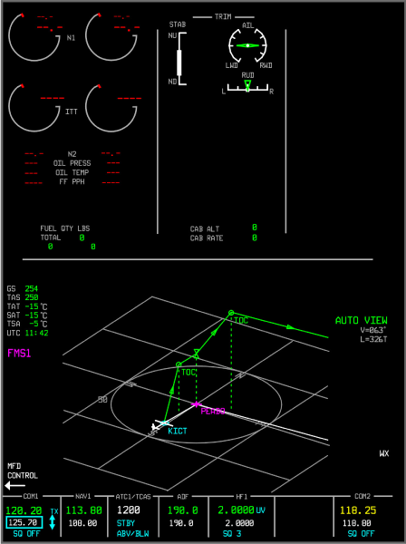
Shoulder (SHLDR) View
Select SHLDR from the 3D PLAN sub-menu using the MENU ADV and PUSH SELECT knobs on the CCP. Use the DATA knob on the CCP to select LEFT SHLDR, CENTER SHLDR, or RIGHT SHLDR views relative to the inbound course. Selecting the shoulder view causes the 3D PLAN Map presentation to switch to a 22 degree horizontal and 75 degree vertical viewing angle relative to the inbound course of the map center waypoint at the time of the selection. The 22 degree horizontal view can be left or right of the inbound course depending on the direction of rotation of view that provides the smallest amount of angular change to the 3D PLAN Map presentation. When SHLDR is selected, use the DATA knob on the CCP to alternate between a left, center, and right display views. The left display is 22 degrees left of the inbound course, the center display is centered on the inbound course, and the right display is 22 degrees right of the inbound course.
TCAS Format
If the CCP TFC pushbutton is pushed, the TCAS (traffic) display will show incase current MFD format is compatible with traffic overlay.
If the CCP TFC pushbutton is pushed, the TCAS ONLY display will show without overlays when current MFD format is not compatible with traffic overlay. If the CCP TFC pushbutton is pushed, the TCAS ONLY display will show when current MFD format is not compatible with traffic overlay. If the CCP TR/WX pushbutton is pushed, the PPOS format will show with a terrain overlay and a traffic overlay.
FMS Text Only (MFD DATA)
The MFD DATA button on the CDU shows the FMS text only format. The FMS text only display format shows FMS text data in the bottom part of the MFD. The FMS text only display format replaces the usual MFD navigation display. The on-side FMS controls the MFD when FMS text is shown. If the on-side PFD shows a PPOS map, the on-side FMS cannot set the MFD to the text only format. The FMS text erases and replaces the MFD display. The FMS text only format is erased with the FMS CDU, or the CCP 1/CCP 2 LWR FRMT pushbutton, or the CCP TFC pushbutton, or the CCP TR/WX pushbutton.
When in FMS text only format, there can be an interval of some seconds after the controls are operated before the MFD shows text data. The CCP 1/CCP 2 LWR FRMT pushbutton causes the subsequent available format to show on the MFD. The CCP 1/CCP 2 LWR FRMT pushbutton has no effect on the PFD.
Radio Altitude Display
The PFD can show radio altitude data.
Weather Radar Display
The PFD can show weather radar data as an overlay display format on compass rose or PPOS displays.
Lightning Detection System Display
The PFD can show lightning strike data on the compass rose or PPOS displays as part of the weather radar overlay display format. The lightning strike data cannot show without the selection of the weather radar overlay display format.
TCAS Display
The PFD can show TCAS data as an overlay display format on compass rose or PPOS displays. The TCAS overlay display format can show on the PFD at the same time as the weather radar overlay display format.
Terrain Avoidance Warning System (TAWS) Display
The PFD can show TAWS data as an overlay display format on the PPOS display. The TAWS overlay display format and the weather radar overlay display format cannot show on the PFD at the same time. The selection of the TAWS overlay display format replaces the weather radar display overlay display format (if shown).
MFD Radio Menu
The MFD can tune the radios that follow:
- VHF communication radio No. 1
- VHF communication radio No. 2
- VHF communication radio No. 3 (optional)
- VHF navigation receiver No. 1
- VHF navigation receiver No. 2
- Air traffic control (ATC) transponder system and TCAS
- Automatic direction finder (ADF)
- HF transceiver No. 1
- HF transceiver No. 2 (optional)
Note:
The radio menu usually shows across the bottom of the pilot MFD.
MFD Control of the VHF Communication System
The MFD can show VHF communication system data. Refer to the VHF communication system for the selection, display, and control of the VHF radios.
MFD Control of the HF Communication System
The MFD can show HF communication system data. Refer to the HF communication system for the selection, operation, and display of the HF communication system data.
MFD Control of the VHF Navigation System
In the VOR operation, the VHF NAV receivers give the en route guidance and terminal-area guidance data. The receivers monitor the VOR signals, from the VOR station selection, along the flight path. The receivers give VOR bearing data on an aeronautical radio incorporated (ARINC) 429 data bus to the PFDs and MFDs through the input/output concentrator unit (IOC). The VHF NAV receiver gives the VOR station-identification audio-signal to the control panel electronic (CPE). The CPE gives the audio signal to the flight compartment speakers or the pilot and copilot headsets.
EICAS Displays
Engine Indicating System Area
The engine indication system (EIS) area has engine data and engine related flags. The full-authority digital engine-control (FADEC) system and the data concentrator unit (DCU) calculate the EIS display data.
Control Surface Area
The control surface area is in the middle of the top of the EICAS display. It shows control surface data and landing gear data.
Crew Alerting System Message Area
The crew alerting system shows system messages to the crew in one of four categories in the sequence of how important they are. That sequence is as follows:
- Warning messages first
- Then caution messages
- Then advisory messages
- Then status messages
Synoptic Pages
The flight crew gets the different synoptic pages on the bottom half of MFD. The A/ICE, ECS, ELEC, FLT, FUEL, HYD, and SUMRY pushbuttons on the CCP 1 or CCP 2 show these pages on onside displays.
When another synoptic page pushbutton is pushed, a new page replaces the synoptic page. The FRMT pushbutton on the DCP shows the summary synoptic page on a compressed PFD. The SUMRY pushbutton on the CCP 1 or CCP 2 shows the summary synoptic page on the bottom half of MFD on onside displays.
The A/ICE pushbutton shows the ANTI-ICE synoptic page. The ECS pushbutton shows the environmental control system synoptic page. The ELEC pushbutton shows the ELECTRICAL synoptic page. The FLT pushbutton shows the FLIGHT CONTROLS synoptic page. The FUEL pushbutton shows the FUEL synoptic page. The HYD pushbutton shows the HYDRAULIC synoptic page. The EFIS can show EICAS data.

EFIS Interfaces
AFD Interfaces
The AFDs have input and output data busses. The AFDs receive and send sensor data from/to different avionics systems through high-speed and low-speed ARINC 429 serial communication-ports.
The AFDs also receive sensor data from the weather radar system and terrain-avoidance warning systems (TAWS) through the ARINC 453 serial communication ports. The weather radar system sends data to the pilot PFD. The other displays (pilot MFD, copilot MFD, and copilot PFD) receive the weather radar data from the pilot PFD. Each display has an input and an output serial communication port for the weather radar data.
The TAWS sends data to the PFDs on an ARINC 453 data bus. The MFDs then receive terrain avoidance warning data from the pilot PFD.
The AFDs also receive discrete control data from the CCP 1, CCP 2 and the RSP.
DCP Interfaces
Each DCP sends control data to the on-side PFD and MFD through ARINC 429 data buses. Each DCP also receives discrete control data from the flight guidance panel (FGP), the on-side BARO utility panel, and remote pushbuttons on the control wheel. The DCP changes the discrete control data to a serial data format and sends that data to the PFD and MFD on ARINC 429 data buses.
CCP 1, CCP 2 Interfaces
The control data outputs from the CCP 1 and CCP 2 are discrete signals. The pilot and copilot MFDs receive control data directly from the CAS and SUMRY pushbuttons and the joystick. The control data from all other pushbuttons goes to the pilot and copilot DCPs. The DCP puts this control data in ARINC 429 serial-data format and sends it to the onside displays.
RSP Interfaces
The control data outputs from the RSP are discrete signals. The RSP has interfaces with the AFDs, inertial reference unit (IRU), air data computer (ADC), radio interface unit (RIU) and the EICAS. The RSP gives the function of reversion control of failed AFDs, IRU, ADC radio tuning functions and controlled EICAS message display
Synthetic Vision System (SVS) (If Installed)
The synthetic vision computer (SVC) sends a video input to the pilot and copilot PFDs. The SVS PFD menu is shown on the PFD. Push the REFS pushbutton on the DCP to get to the REFS menu. Select the SVS menu items to show the SVS image on the pilot and/or copilot PFDs.
System Interface
The EFIS has interfaces with the systems/components that follow:
- Fight Guidance Panel
- HF Communication System
- Radio Interface Unit (RIU)
- Control Wheel
- Engine Indication and Crew Alerting System (EICAS)
- Input/Output Concentrator (IOC) Unit
- Air Data System
- Synthetic Vision System (SVS)
- Weather Radar System
- Terrain-Avoidance Warning System (TAWS)
- Traffic Alert and Collision-Avoidance System
- Radio Altimeter System
- Inertial Reference System (IRS)
- Lightning Detection System
- VHF Navigation System
- Flight Management System
- Maintenance Diagnostic Computer
- Full-Authority Digital Engine-Control (FADEC) System
Note:
The EFIS gives data on what is shown on the display unit and where it is shown. Only general data is given in the EFIS. Data about the specific conditions and colors are given in the related sections of each system.
02/05/16
System Monitoring
The CCP L/R switch sets which MFD the CCP controls. The CCP FRMT pushbutton then sets the type of display from the FORMAT menu, for the bottom part of that MFD. The CCP can show the PPOS map, the PLAN map, and the TCAS format types of displays. The CDU can show the FMS text only on its display (MFD DATA).
The AFDs have a comparator function for the very important data of the display. This data is compared against data from a cross-side source before it is shown on the display. If there is a mismatch in the data, a comparator flag will be shown on the display as well as an EFIS MISCOMPARE (caution) CAS message. The AFDs also have a non-comparator function for the very important data of the display that have multiple sources. This data is compared against data from a cross-side source before it is shown on the display. If it is found that the cross-side data is absent or invalid, an EFIS COMPARATOR INOP (caution) CAS message is shown and means that one or all comparators do not operate.
A main application code in the AFD has diagnostic checks on the hardware. Failures found by the diagnostic checks are recorded in the AFD non-volatile memory (NVM) and sent to the MDC.
The AFDs subsystems and their software do monitoring functions to find failures or data corruption to tell the flight crew. There are a graphics-device driver software monitoring function, a programmable timer hardware monitoring function and a display head module (DHM) main processor that does test and monitoring functions.
The graphics-device driver software continuously monitors the integrity of the graphics data. The programmable timer in the graphics first in first out (FIFO) hardware prevents a frozen screen to be shown. The time has a program to show a black display if a graphics command is not written to the FIFO by the main processor for three refresh cycles (50 msec).
The DHM processor does a self-test at power-up. If the test fails, the processor will prevent data to be shown on the displays. The DHM contains diagnostic checks and faults sensed are recorded in the NVM. The DHM does validity checks on the received data. If the data received is incorrect, a fail flag will replace the applicable data on the displays.
The EICAS messages that follow are related to the Electronic Flight-Instrument System (EFIS):
|
EICAS MESSAGE(S) |
LEVEL (COLOR) |
|---|---|
|
EFIS COMPARATOR INOP |
CAUTION (amber) |
|
EFIS MISCOMPARE |
CAUTION (amber) |
|
PFD X-TALK FAIL |
CAUTION (amber) |
|
MFD X-TALK FAIL |
ADVISORY (cyan) |
10/21/20
Component Location Index
| Component Location Index | |||
|---|---|---|---|
| IDENT | DESCRIPTION | LOCATION | IPC REF |
| A29 | ADAPTIVE FLIGHT-DISPLAY UNIT MFD1 | ZONE(S) 211 | 31-61-01 |
| A28 | ADAPTIVE FLIGHT-DISPLAY UNIT MFD2 | ZONE(S) 212 | 31-61-01 |
| A27 | ADAPTIVE FLIGHT-DISPLAY UNIT PFD1 | ZONE(S) 211 | 31-61-01 |
| A26 | ADAPTIVE FLIGHT-DISPLAY UNIT PFD2 | ZONE(S) 212 | 31-61-01 |
| PL7 | DISPLAY CONTROL PANEL | ZONE(S) 211 | 31-61-05 |
| PL8 | DISPLAY CONTROL PANEL | ZONE(S) 212 | 31-61-05 |
| PL25 | CURSOR CONTROL PANEL 1 | ZONE(S) 211 | 31-61-09 |
| PL60 | CURSOR CONTROL PANEL 2 | ZONE(S) 212 | 31-61-09 |
| PL27 | REVERSION SELECT PANEL | ZONE(S) 211 | 31-61-13 |