


Overview
The main landing gear (MLG) and the nose landing gear (NLG) hold the aircraft in a horizontal attitude when it is on the ground. They also give shock protection to the aircraft during landings and when the aircraft is taxiing. There are two MLG installations on the aircraft. Each MLG is behind the rear spar, near the root rib of the wing.

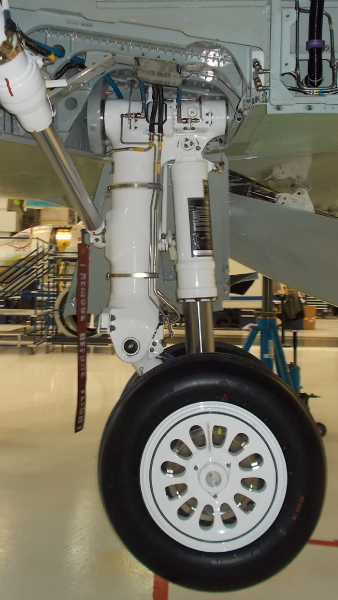
Main Landing Gear Main Fitting
The primary component of the main landing gear (MLG) is the main fitting which is not a line replaceable unit.
The main fitting is a hollow cylinder. It has a crossbeam at the top and a fork at the bottom where it attaches to the trailing arm. A pintle pin in the main fitting crossbeam attaches the MLG to the structure. A cross pin safeties the pintle pin.
The auxiliary extend actuator attaches to lugs on the top of the main fitting crossbeam. Below the crossbeam at the rear of the main fitting is a lug with a spherical bearing to which the MLG shock strut attaches.
The side brace actuator attaches to a pin on the side of the main fitting. The linkage, which operates the main gear door, attaches to the door linkage attachment point on the aft end of the main fitting. The MLG uplock roller brackets are at the bottom of the main fitting. There is a bracket for the weight-on-wheels (WOW) proximity sensors at the bottom of the two main fitting lugs.

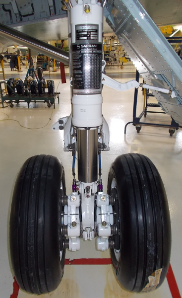
Main Landing Gear Shock Strut
The shock strut is a gas and oil type with a metering pin and an orifice that control the rate at which the strut compresses. The orifice controls the subsequent extension of the shock strut. The shock strut has a cylinder and a piston. The space between the internal diameter of the cylinder and the external diameter of the piston is the recoil damping chamber. The cylinder has a support tube with an orifice and the piston has a metering pin that moves through the orifice.
The clearance between the orifice and the metering pin is adjusted, when the piston compresses into the cylinder. This controls the flow of fluid from the piston into the cylinder and the rate at which the shock strut absorbs energy. During compression, transfer holes in the support tube and upper bearing let oil flow into the space between the cylinder and the piston. Because the volume of this space increases, oil goes through and around a rebound ring. The rebound ring decreases the flow of hydraulic fluid in one direction.
During extension of the shock strut, the volume decreases and oil flows only through holes in the rebound ring. This controls the speed of the extension. A lower bearing attached to the cylinder and an upper bearing attached to the piston support the piston during its travel. The lower bearing has a dynamic seal, static packing, packing retainers, spare dynamic seal, and spare static packing. The spare static packing can replace the first static packing if it becomes necessary. A scraper on the inner face of the lower bearing keeps out contamination.
At the top of the cylinder there is a main fitting attachment clevis which has two lugs. The lugs attach the shock strut to the aft of the main fitting crossbeam. The bottom of the shock strut piston has a lug which attaches to the trailing arm. There are fittings for lubrication installed in the lugs through which grease is supplied for the spherical bearings. The shock strut is filled with hydraulic fluid (MIL-PRF-5606) through a oil filler valve at the bottom of the piston. The strut is also pressurized with nitrogen through a charging valve at the top of the cylinder.

Trailing Arm
The trailing arm is a beam which connects at its higher end to the main fitting with a pivot pin. It lets the main wheel axle go up and down to transmit loads into the shock strut. The shock strut attaches to the trailing arm above the axle socket. The bottom of the trailing arm connects to the main wheel axle with a pin. A sealing cap at the top of the trailing arm keeps out contamination. There is a drain hole at the bottom of the trailing arm.
On each side of the trailing arm around the axle socket are flanges on which to attach the brakes. Each brake flange has a eutectic plug to allow monitoring of the brake unit for overtemperature conditions. A jacking pad can be installed on a pair of lugs below the axle socket.

Main Gear Harness
Each MLG has two electrical harnesses .The routing of the harnesses is aft of each main fitting on the inboard and outboard sides. The weight-on-wheels (WOW) proximity sensors are on the aft face of the main fitting at the bottom. The harnesses are also installed on the inboard and outboard aft side of the trailing arm. The harnesses go through holes in the trailing arm and through the axle to the wheel speed transducers.

Main Landing Gear Axle
The MLG axle is a hollow tube which is installed through the axle socket of the trailing arm. A bolt safeties the axle to the trailing arm. The axle has two holes to connect the MLG harnesses to the wheel speed transducers. The two ends of the axle have threads to attach the nuts that safety the main wheels on the MLG.

11/27/15
System Interface
The MLG has interfaces with the system/component that follows:
- Main Gear Extension and Retraction
- Proximity-Sensor Electronic Unit (PSEU)
10/19/20
Component Location Index
| Component Location Index | |||
|---|---|---|---|
| IDENT | DESCRIPTION | LOCATION | IPC REF |
| - | MAIN LANDING GEAR (LH) | ZONE(S) 730 | 32-11-01 |
| - | MAIN LANDING GEAR (RH) | ZONE(S) 740 | 32-11-01 |
| - | MAIN LANDING GEAR (MLG) SHOCK STRUT (LH) | ZONE(S) 730 | 32-11-05 |
| - | MAIN LANDING GEAR (MLG) SHOCK STRUT (RH) | ZONE(S) 740 | 32-11-05 |
| - | TRAILING ARM (LH) | ZONE(S) 730 | 32-11-09 |
| - | TRAILING ARM (RH) | ZONE(S) 740 | 32-11-09 |
| - | MAIN GEAR HARNESS (INBD-LH) | ZONE(S) 730 | 32-11-13 |
| - | MAIN GEAR HARNESS (INBD-RH) | ZONE(S) 740 | 32-11-13 |
| - | MAIN GEAR HARNESS (OUTBD-LH) | ZONE(S) 730 | 32-11-13 |
| - | MAIN GEAR HARNESS (OUTBD-RH) | ZONE(S) 740 | 32-11-13 |
| - | MAIN LANDING GEAR (MLG) AXLE (LH) | ZONE(S) 730 | 32-11-25 |
| - | MAIN LANDING GEAR (MLG) AXLE (RH) | ZONE(S) 740 | 32-11-25 |