


Overview
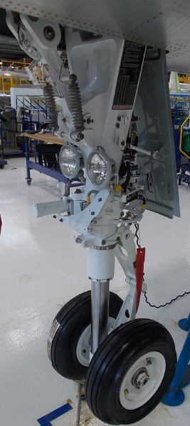
The nose landing gear is in the wheel well below the flight compartment. The nose gear retracts forward and up into the nose gear wheel well. During taxiing procedures, the pilot can change the direction of the aircraft with the nosewheel steering control system.

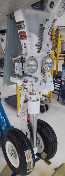
Nose Landing Gear Shock Strut
The shock strut is a gas and oil type with a metering pin and an orifice that controls the rate at which the strut compresses. The orifice controls the subsequent extension of the shock strut. The shock strut has a cylinder and piston.
The space between the internal diameter of the cylinder and external diameter of the piston is the recoil damping chamber. The cylinder has a support tube with an orifice. The piston has a metering pin that moves through the orifice.
When the piston compresses into the cylinder, the clearance between the orifice and the metering pin is adjusted. This controls the flow of fluid from the piston into the cylinder and the rate at which the shock strut absorbs energy. During compression, transfer holes in the piston let oil flow into the annular space between the cylinder and the piston. Because the volume of the annular space increases, oil goes through and around a rebound ring in the annulus. The rebound ring decreases the flow of hydraulic fluid in one direction.
During the extension of the shock strut, the volume decreases and oil flows only through holes in the rebound ring. This controls the speed of the extension. A lower bearing attached to the cylinder and an upper bearing attached to the piston support the piston during its travel. The lower bearing has a dynamic seal, a static seal, retaining collar, and a spare dynamic seal. The spare dynamic seal can replace the dynamic seal if it becomes necessary. A scraper ring is installed on the inner face of the retaining collar to keep out contamination.
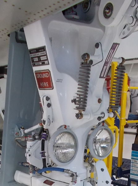
At the top of the cylinder, a retraction actuator attachment has two lugs. The lugs attach the retraction actuator to the front of the shock strut. There are two lugs on the front of the shock strut which attach to the NLG drag brace. Also at the top is a main fitting attachment which has two lugs that attach the aircraft structure. At the bottom of the shock strut there are two sets of lugs which attach to the upper and lower torque links.
The strut is filled with hydraulic fluid (MIL-PRF-5606) and pressurized with nitrogen. The oil is added through an oil filler port at the top of the cylinder. The nitrogen is added through a charging valve at the bottom of the cylinder.


Nose Gear Harness
The nose gear has two electrical harnesses on the shock strut. The two harnesses are weight-on-wheels (WOW) No. 1 and the WOW No. 2. Each harness connects to a WOW proximity sensor. The WOW proximity sensors are on the two sides of the shock strut steering cuff, near the upper torque link. The WOW targets are on the two sides of the upper torque link at the top.
The WOW No. 1 harness also contains the harness for the nosewheel steering. The nosewheel steering harness connects to the electrohydraulic servo valve and to the rotary variable transducer. The WOW No. 2 harness has electrical connections for the nose gear lights and the overtow microswitch.


Nose Landing Gear Drag Brace
The nose gear drag brace locks the nose gear in the extended position. The upper and lower drag braces attach together at a pivot point in the center. Two aircraft attachment points attach the upper drag brace to the aircraft structure. The lower drag brace attaches to NLG drag brace lugs of the NLG shock strut. The upper drag brace has two retraction actuator lugs on which to attach the nose gear retraction actuator. The upper drag brace has an internal actuator which locks the upper and lower drag braces at their pivot point.
Two auxiliary downlock springs attach to the lower drag brace and to the shock strut. These springs ensure the drag braces fully unfold and help the downlock engage. The downlock unlocks hydraulically to let the drag braces fold when the nose gear retracts.
As a safety device, a nose gear ground lock pin is installed in the upper drag brace while the aircraft is on the ground. This mechanically locks the internal actuator in the upper drag brace in the locked position.
Two WOW proximity sensors on the upper drag brace send downlock indications to the proximity sensor electronic unit (PSEU).


Drag Brace Harness
The nose gear upper drag brace has two electrical harnesses called downlock No. 1 and No. 2. They connect to the aircraft electrical system and upper drag brace. WOW proximity sensors are attached to the ends of the two harnesses. These sensors signal the PSEU when the nose gear is down and locked.

Auxiliary Downlock Spring
Two auxiliary downlock springs attach to the lower nose gear drag brace at the top and the nose gear shock strut at the bottom. The springs are in tension when the drag braces fold. When the nose gear extends and the drag braces unfold, the springs push against the shock strut. This ensures the drag braces move to the fully locked position.

11/28/15
System Interface
The nose landing gear has interfaces with the following systems/component:
- Landing Gear Control System
- Nose Gear Extension and Retraction
- Proximity Sensor Electronic Unit (PSEU)
10/19/20
Component Location Index
| Component Location Index | |||
|---|---|---|---|
| IDENT | DESCRIPTION | LOCATION | IPC REF |
| - | NOSE LANDING GEAR (NLG) SHOCK STRUT | ZONE(S) 710 | 32-21-05 |
| - | NOSE GEAR STEERING AND SENSOR HARNESS NO. 1 |
ZONE(S) 710 | 32-21-09 |
| - | NOSE GEAR LIGHTS AND SENSOR HARNESS NO. 2 |
ZONE(S) 710 | 32-21-09 |
| - | NOSE LANDING GEAR (NLG) DRAG BRACE | ZONE(S) 710 | 32-21-13 |
| - | AUXILIARY DOWNLOCK SPRING | ZONE(S) 710 | 32-21-17 |
| - | DRAG BRACE HARNESS | ZONE(S) 710 | 32-21-21 |