


11/10/25
Overview
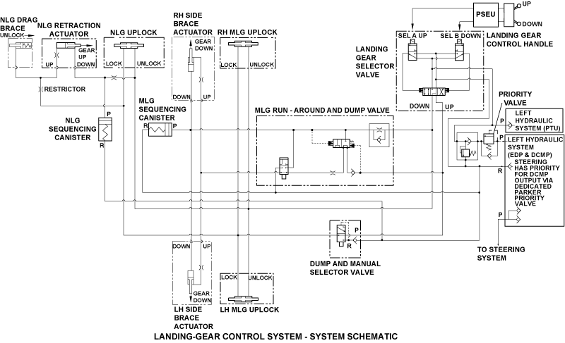
The landing-gear control system uses signals from the proximity-sensor electronic unit (PSEU) to control the landing gear. The main and nose landing gear proximity sensors give data to the PSEU which controls the landing-gear selector valve. The landing-gear selector valve controls the landing gear position through the commands of the landing-gear control handle.
11/10/25
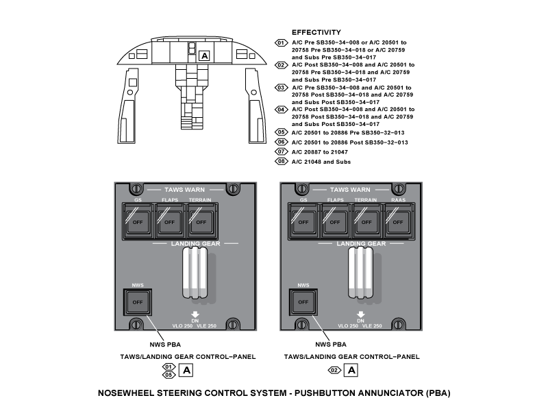
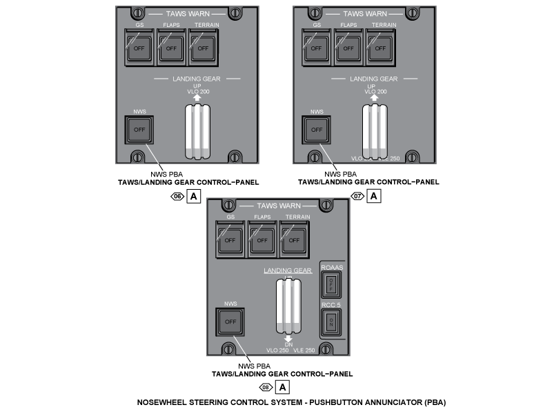
Landing Gear Control Handle
The landing gear control handle is in the flight compartment on the main instrument panel. The pilot and copilot have access to the control handle. The landing gear control handle is part of the TAWS WARN/LANDING GEAR control panel.
The control handle is a two-position, three-pole switch that controls landing gear extension and retraction. When the control handle is set to UP or DN, a signal is sent to the PSEU to control the landing gear selector valve. The landing gear control handle has two mechanical locks to keep it in the set position.


Landing Gear Selector Valve
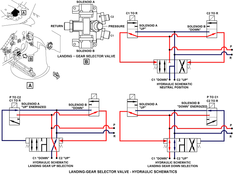
The landing gear selector valve is in the aft center of the right main landing gear (MLG) wheel well. The landing gear selector valve is a four-direction, three-position, solenoid operated valve. It sends hydraulic pressure to the landing gear up or down hydraulic lines. The selector valve has a piston, springs, and two solenoid operated valves.
When solenoids A and B are de-energized (no electrical power on the aircraft), there is hydraulic pressure at two sides of the valve piston. This pressure, with the springs, holds the piston in the center position and sends no pressure to the C1 and C2 ports. In this position, the two ports are connected to the hydraulic system return lines.
When solenoid A is energized, the pressure on that side of the piston is connected to the hydraulic system return lines. Pressure on the opposite end of the piston pushes it and connects hydraulic pressure with the C2 port and the landing gear-up hydraulic lines. The landing gear-down lines are connected through the C1 port to the hydraulic system return line.
When solenoid B is energized, the piston moves in the opposite direction. Hydraulic pressure is connected to the gear-down C1 port and C2 port is connected to the hydraulic system return lines.

Main Landing Gear Sequencing Canister
The main landing gear (MLG) sequencing canister is in the down hydraulic line of the side brace actuator in the aft inboard side of the right MLG wheel well. The MLG sequencing canister has a cylinder, piston, and spring. It also has an end cap, nut, and locking piece.
When the landing gear control handle is set to DN, low-pressure hydraulic fluid moves the MLG sequencing canister piston. This decreases the pressure to the side brace actuators. At the same time, the landing gear uplocks are unlocked. When the MLG sequencing canister piston goes to full travel, high-pressure hydraulic fluid is sent to the side brace actuators. The initial decreased pressure lets the landing gear uplocks unlock at smaller loads so the start of the landing gear extension makes less noise.

Main Landing Gear Side Brace Actuator
The side brace actuator extends and retracts the MLG. It has an internal lock mechanism that locks it in the extended position to make a rigid side brace. Two springs and hydraulic pressure lock the actuator during landing gear extension. The springs are hydraulically released when the actuator retracts.
The proximity sensor in the indicator assembly sends locked and unlocked indications to the proximity sensor electronic unit (PSEU). Each end of the side brace actuator has a spherical bearing to attach it to the aircraft structure and the MLG.
The side brace actuator is pressurized by the left hydraulic system. The port to extend the cylinder lets fluid go into the cylinder for the extension of the piston. A port to retract the cylinder and a transfer tube move fluid to the opposite end of the cylinder to release the lock and retract the piston.
A ring nut safeties the gland housing on the open end of the cylinder. Internal and external packings seal the gland housing. A scraper ring on the housing keeps out contamination. Keys and a lock nut safety the rod end on the end of the piston. The rod end has a hole for a ground lock pin and a dust cover to keep contamination out of the ground lock pin hole.
When the landing gear control handle is moved to the DN position, the landing gear selector valve sends hydraulic pressure to the port for extension. When the piston reaches the fully extended position, the lock segments move up the slope of the lock piston. The lock segments engage with the end of the cylinder and prevent retraction of the piston.
During emergency extension of the landing gear, the hydraulic pressure bypasses the side brace actuator and the piston moves freely.
When the landing gear control handle is moved to the UP position, the landing gear selector valve sends hydraulic pressure to the port for retraction. The hydraulic pressure pushes the lock piston against the force of the springs. The lock segments then move freely down the slope of the locking piston, which lets the piston move into its cylinder.
Four bolts attach an indicator assembly to the cylinder. A striker collar in the lock piston moves the lever in the indicator assembly. Movement of the lever causes a target to move in front of the two proximity sensors. A spring keeps a positive pressure on the proximity sensors to prevent indication errors caused by vibration.


Main Landing Gear Side Brace Harness
There are two harnesses (downlock sensor No. 1 and No. 2) on each side brace actuator. The harnesses are on the cylinder and are connected from the airframe interface in the wheel well to the indicator assembly.

Main Landing Gear Uplock
The main landing gear uplocks are on the aircraft structure in the two main gear wheel wells. The main gear uplock holds the main gear in the retracted position. It locks mechanically and, for usual operation, it releases hydraulically. For emergency operation, a manual release handle (connected to a cable) releases the latch lever mechanically. The uplock mechanism has a housing, latch lever with hook, two tension springs, and actuator with a piston.
When the main gear retracts, a roller at the bottom of the MLG main fitting engages the latch hook which locks the gear up. The two tension springs make sure that the uplock is held in a positive lock position.
When the main gear extends, hydraulic pressure from the left hydraulic system extends the actuator piston and releases the uplock. The actuator piston moves the latch lever and latch hook away from the roller which releases the gear. The weight of the gear then turns the hook, and the landing gear extends.


Main Landing Gear Runaround and Dump Valve
The runaround and dump valve is a group of two valves that come as one assembly. The runaround valve is a two-position, spring-biased, usually closed valve. It is used for usual extension and retraction. The runaround valve bypasses hydraulic fluid from the gear upline to the gear downline. This decreases hydraulic flow from the side brace actuators.


Nose Landing Gear Sequencing Canister
The nose landing gear (NLG) sequencing canister is in the down hydraulic line of the NLG retraction actuator installed in the left side of the NLG wheel well. The NLG sequencing canister has a cylinder, piston, and spring. It also has an end cap, nut, and locking piece. When the landing gear control handle is set to DN, low-pressure hydraulic fluid moves the NLG sequencing canister piston. This decreases the pressure to the NLG retraction actuator. At the same time, the landing gear uplocks are unlocked.
When the NLG sequencing canister piston goes to full travel, high-pressure hydraulic fluid is sent to the NLG retraction actuator. The initial decreased pressure lets the landing gear uplocks unlock at smaller loads so the start of the landing gear extension makes less noise.

Nose Landing Gear Restrictor
The restrictor is in the aft of the NLG wheel well. The restrictor is in the up hydraulic line, upstream of the NLG drag brace and the NLG retraction actuator. When the landing gear control handle is set to UP, the restrictor decreases the hydraulic fluid flow. This decreases the retract speed and lets the NLG retract smoothly with less noise.

Nose Landing Gear Retraction Actuator
The NLG retraction actuator retracts and extends the NLG.
It has a cylinder and piston, gland nut, scraper, and seals to prevent hydraulic fluid leaks. The cylinder end of the nose gear retraction actuator is attached to lugs at the top of the shock strut. The piston end is attached to the nose gear drag brace.
Pressure from the left hydraulic system operates the nose gear retraction actuator. To control the rate of extension and retraction, the nose gear retraction actuator internally has an orifice and two restrictors. When the nose gear retraction actuator extends, the NLG retracts. When it retracts, the NLG extends. For emergency extension, the nose gear retraction actuator is bypassed to return and moves freely with the shock strut.

Nose Landing Gear Uplock
The NLG uplock is on the aircraft structure in the nose gear wheel well. The nose gear uplock holds the NLG in the retracted position. The uplock is mechanically locked and, for usual operation, hydraulically released. For emergency operation, the manual release handle mechanically releases the uplock.
The uplock mechanism has a housing, latch lever and hook, two tension springs, and uplock actuator. When the NLG is retracted, a roller on the gear engages the latch hook to lock the NLG up. The two tension springs ensure the uplock is held in a positive lock position. To release the uplock, hydraulic pressure from the left hydraulic system operates the uplock actuator. The uplock actuator piston moves the latch lever and roller away from the latch hook. The weight of the NLG turns the hook and the NLG extends.


System Operation
The landing gear selector valve sends hydraulic pressure to retract the landing gear when all the following conditions are met:
- Landing gear control system senses MLG and NLG weight off wheels
- LANDING GEAR RETRACT COMMAND (in PSEU logic) = TRUE (confirmation that the handle is UP)
- Nosewheel is in the center position
- Main and nose landing gear uplocks are not uplocked
When the landing gear control handle is moved to the UP position, it sends a signal to the PSEU to retract the landing gear. If these conditions are all correct, the PSU applies 28 VDC to the retract side (energizes solenoid A) of the landing gear selector valve.
The left hydraulic system supplies hydraulic pressure for usual retraction of the MLG and NLG . Pressure to the main gear side brace actuators unlocks the MLG. Pressure to the NLG drag brace unlocks the NLG. The side brace actuators then retract the MLG, and the NLG retract actuator retracts the NLG.
The landing gear selector valve sends hydraulic pressure to extend the landing gear when:
- LANDING GEAR RETRACT COMMAND (in PSEU logic) = TRUE (confirmation that the handle is DN)
If this condition is correct, the PSEU supplies a continuous 28 VDC source for the landing gear extension. When the landing gear control handle is set to DN, the handle connects the 28 VDC to the extend side (energizes solenoid B) of the landing gear selector valve. At this time, low-pressure hydraulic fluid moves the piston of the MLG and NLG sequencing canisters. This decreases the pressure to the side brace actuators and the NLG retraction actuator. At the same time, hydraulic pressure unlocks the MLG and NLG uplocks.
When the piston of the MLG and NLG sequencing canisters to full travel, high-pressure hydraulic fluid is sent to the side brace actuators and NLG retraction actuator. The initial decreased pressure lets the landing gear uplocks unlock at smaller loads and the start of the landing gear extension makes less noise. The hydraulic pressure then extends the MLG side brace actuator and retracts the NLG retraction actuator to extend the landing gear.
The GEAR DISAGREE caution message will show when one of the following conditions occur:
- The landing gear does not reach the position that agrees with the landing gear control handle within the maximum gear swing time-out.
- A landing gear fails to move when commanded
- There is an uncommanded movement of the landing gear
The EICAS message that follows is related to the landing-gear control system:
| EICAS MESSAGE(S) | LEVEL (COLOR) |
|---|---|
| GEAR DISAGREE | CAUTION (amber) |
For MLG retraction, left hydraulic system hydraulic pressure is sent to the side brace actuators. The side brace actuators unlock and retract to retract the left and right MLG. When the MLG moves to the fully retracted position, the uplock rollers on the gear engage and turn the uplock hook. When the uplock hook turns, the roller on the latch lever engages the recess and holds the hook in the locked position. The uplock tension springs apply pressure to the latch lever to hold the roller in a recess.
During usual extension, the left hydraulic system supplies hydraulic pressure to the side brace actuators and to the main gear uplocks. Hydraulic pressure extends the uplock piston and moves the latch lever and latch hook away from the roller which releases the gear. After the latch hook releases, the weight of the gear turns the hook, and the gear uplock roller moves out of the uplock.
After the uplock releases the roller on the main gear, hydraulic pressure extends the side brace actuator and pushes the gear to the extended position. When the landing gear is fully extended, the side brace locks internally to keep the gear down.
When it is necessary to make an emergency extension of the MLG, the pilot pulls the manual release handle. This causes the main gear uplocks to unlock mechanically, and hydraulic fluid bypasses the side brace actuator. The MLG moves away from the main gear uplock. Hydraulic pressure from the right hydraulic system goes to the auxiliary extend actuator which helps the gear go to the fully extended position. The side brace actuator moves freely with the gear, and the internal downlock engages.
For MLG retraction, left hydraulic system hydraulic pressure is sent to the side brace actuators.
The side brace actuators unlock and retract the left and right MLG. When the MLG moves to the fully retracted position, the uplock rollers on the gear engage and turn the uplock hook. When the uplock hook turns, the roller on the latch lever engages the recess and holds the hook in the locked position. The uplock tension springs apply pressure to the latch lever to hold the roller in a recess.
During a usual extension, the left hydraulic system supplies hydraulic pressure to the side brace actuators and to the main gear uplocks. Hydraulic pressure extends the uplock piston and moves the latch lever and the latch hook away from the roller which releases the gear. After the latch hook releases, the weight of the gear turns the hook, and the gear uplock roller moves out of the uplock.
After the uplock releases the roller on the main gear, hydraulic pressure extends the side brace actuator and pushes the gear to the extended position. When the landing gear is fully extended, the side brace locks internally to keep the gear down.
When it is necessary to make an emergency extension of the MLG, the pilot pulls the manual release handle. This causes the main gear uplocks to unlock mechanically and hydraulic fluid bypasses the side brace actuator. The MLG moves away from the main gear uplock. Hydraulic pressure from the right hydraulic system goes to the auxiliary extend actuator which helps the gear go to the fully extended position. The side brace actuator moves freely with the gear and the internal downlock engages.
For NLG retraction, left hydraulic system pressure is sent to the nose gear retraction actuator. Hydraulic pressure is also sent to the internal actuator in the nose gear upper drag brace. The hydraulic pressure unlocks the internal actuator of the upper drag brace to let it fold. When the drag brace is unlocked, the hydraulic pressure extends the nose gear retraction actuator piston and retracts the NLG.
While the NLG retracts the drag brace continues to fold until it and the NLG is in the fully retracted position.
While the NLG moves to the fully retracted position the nose gear uplock roller engages and turns the uplock hook. When the uplock hook turns, the roller on the latch lever engages the lock and holds the hook in the locked position. The uplock tension springs apply pressure to the latch lever to hold the roller in the locked position.
For the usual extension, left hydraulic system pressure extends the uplock actuator piston. The piston moves the latch lever to lift the roller out of the locked position. With the latch roller released, the weight of the NLG turns the hook and the gear uplock roller is released from the uplock. The left hydraulic system pressure retracts the nose gear retraction actuator piston and extends the NLG. The drag brace then unfolds to the extended position.
When the NLG is fully extended, the auxiliary downlock springs push the NLG drag brace fully unfolded which locks the NLG down.
When it is necessary to make an emergency extension of the NLG, the pilot pulls the landing-gear manual-release handle. This causes the nose-gear uplock to unlock mechanically. Also, hydraulic fluid bypasses the nose-gear retraction actuator and the internal actuator of the upper drag brace. The NLG moves away from the nose-gear uplock. With the aid of airflow the NLG moves down freely.
When the NLG fully extends, the auxiliary downlock springs push the NLG drag brace to the fully unfolded position. At the same time the forward-door assist-springs operate against the airload on the forward doors. These two sets of springs help the NLG to get a downlock.


11/26/15
System Interface
The landing gear control system has interfaces with the systems/components that follow:
- Main Gear Extension and Retraction
- Nose Gear Extension and Retraction
- Nosewheel Steering Control System
- Main Landing Gear (MLG) Proximity Sensor
- Nose Landing Gear (NLG) Proximity Sensor
- Proximity Sensor Electronic Unit (PSEU)
- TAWS/LANDING GEAR Control Panel
10/19/20
Component Location Index
| Component Location Index | |||
|---|---|---|---|
| IDENT | DESCRIPTION | LOCATION | IPC REF |
| V9 | LANDING-GEAR SELECTOR VALVE | ZONE(S) 160 | 32-31-01 |
| - | SEQUENCING CANISTER | ZONE(S) 160 | 32-31-05 |
| - | RESTRICTOR | ZONE(S) 120 | 32-31-09 |
| S125 | LANDING-GEAR CONTROL HANDLE | ZONE(S) 210 | 32-31-13 |
| - | MAIN-GEAR UPLOCK (LH) | ZONE(S) 730 | 32-32-05 |
| - | MAIN-GEAR UPLOCK (RH) | ZONE(S) 740 | 32-32-05 |
| - | SIDE BRACE ACTUATOR (LH) | ZONE(S) 730 | 32-32-07 |
| - | SIDE BRACE ACTUATOR (RH) | ZONE(S) 740 | 32-32-07 |
| - | SIDE BRACE HARNESS (LH-AFT) | ZONE(S) 730 | 32-32-09 |
| - | SIDE BRACE HARNESS (LH-FWD) | ZONE(S) 730 | 32-32-09 |
| - | SIDE BRACE HARNESS (RH-AFT) | ZONE(S) 740 | 32-32-09 |
| - | SIDE BRACE HARNESS (RH-FWD) | ZONE(S) 740 | 32-32-09 |
| - | NOSE-GEAR RETRACTION ACTUATOR | ZONE(S) 710 | 32-33-01 |
| - | NOSE-GEAR UPLOCK | ZONE(S) 121 | 32-33-05 |
| - | RUN-AROUND AND DUMP VALVE | ZONE(S) 160 | 32-34-05 |