


Overview
The landing gear emergency extension system is used if an electrical system, left hydraulic system, or actuator becomes defective, preventing usual extension.
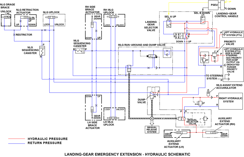
When the manual release handle is pulled, the main and nose gear uplocks are mechanically released. The nose landing gear (NLG) falls freely to the extended position and is helped by aerodynamic force. The main-gear auxiliary extend-actuators will push the main landing gear (MLG) to the extended position. The mechanical locks in the nose gear drag brace, and the main gear side brace actuators lock the gear in the extended position.

Landing Gear Manual Release Handle
The manual release handle is in the flight compartment center pedestal. It goes through the floor and connects to the main quadrant. The top of the handle is below the level of the center pedestal when it is in the stowed position. Movement from the manual release handle is transmitted through the main quadrant to the uplocks, runaround and dump valve, and dump and manual selector valve.

Runaround and Dump Valve
The runaround and dump valve is in the top of the main gear wheel well. It is connected to the MLG quadrant which is connected to the manual release handle cable loop. The runaround and dump valve is a group of two valves that come as one assembly.
The run-around valve is a 2-position, spring-biased, usually closed valve. It is used for usual extension and retraction. The run-around valve bypasses hydraulic fluid from the gear up line to the gear down line. This will decrease the hydraulic flow from the side brace actuators during the MLG extension.
For the emergency extension function, the MLG quadrant operates the dump valve in the runaround and dump valve. This dump valve bypasses hydraulic pressure from the side brace actuators through the return lines to the reservoir of the left hydraulic system. This lets the side brace actuators move freely for the emergency extension.


Dump and Manual Selector Valve
The dump and manual selector valve is a group of two valves connected together and operated by the MLG quadrant. It is in the top of the MLG wheel well near the runaround and dump valve. The two valves are operated by one adjustable link attached to the MLG quadrant.
During usual operation, the dump valve (of the dump and manual selector valve) connects the up port of the selector valve with the up side of the NLG and MLG uplocks. It also connects the up port of the selector valve with the NLG retraction actuator and the side brace actuators. For the emergency release function, the dump valve (of the dump and manual selector valve) moves and changes these connections to the return side of the left hydraulic system. The NLG up port, all uplock up ports, and the side brace actuator ports allow the pressure to go back to the left reservoir. This lets the fluid flow freely while the landing gear extends.
For usual operation, the manual selector valve connects the main gear auxiliary extend actuator to the return line of the right hydraulic system. This lets hydraulic fluid flow freely while the actuator moves with the gear. When the manual release handle is pulled, the MLG quadrant moves the valve input lever. The valve then closes the return port and connects the right hydraulic system pressure to the main gear auxiliary extend actuators. This lets the MLG extend.


Main Quadrant
The main quadrant is below the flight compartment floor, aligned with the manual release handle. An adjustable turnbuckle connects the main quadrant to the manual release handle. Cables attach the main quadrant to the main and nose gear uplocks, the runaround and dump valve, and the dump and manual selector valve. When the manual release handle turns the main quadrant, the main and nose gear cables are operated at the same time.

Landing Gear Assist Accumulator
The landing gear assist accumulator is in the right hydraulic system compartment. It extends the MLG if hydraulic pressure is not available. The accumulator is charged with dry nitrogen gas. The landing gear assist accumulator is a piston type unit which is gas charged and has a volume of 75 in3 (1,229.03 cm3).
The accumulator pressure is set to have sufficient hydraulic fluid to extend the MLG when the accumulator is used. The nitrogen end has a fitting to connect it to the landing gear assist accumulator charge manifold. The hydraulic end has a fitting to connect it to the aircraft right hydraulic system.

Landing Gear Assist Accumulator Charge Manifold
The landing gear assist accumulator charge manifold is found on the FS635.00 bulkhead in the rear fuselage battery compartment. The landing gear assist accumulator charge manifold has a pressure gauge and a charge valve. The gauge is calibrated from 0 to 5,000 psi in 200 psi increments. The charge valve supplies a procedure for the gas side of the landing gear assist accumulator to be manually pressurized.

Main Gear Auxiliary Extend Actuator
There are two main gear auxiliary extend actuators , one on each of the left and right main gear. The auxiliary extend actuator has a cylinder with a piston. The piston end of the actuator attaches to lugs on the top of the MLG main fitting. The cylinder end attaches to the aircraft structure. The right hydraulic system supplies pressure to the main gear auxiliary extend actuator.
The main gear extension and retraction system only uses the auxiliary extend actuator in an emergency. During usual extensions and retractions, the piston moves freely with the movement of the landing gear. For emergency extension, the main gear auxiliary extend actuator makes sure that the main gear extends fully.

System Operation
When the manual release handle is pulled, the following operations occur:
- Manual release handle turns the main quadrant.
- Through the cables, the main quadrant pulls the NLG and MLG uplock manual release levers and the MLG quadrant.
- MLG quadrant moves the spools on the runaround and dump valve, and the dump and manual selector valve.
- Uplock manual release levers release the uplock hooks.
- Dump valves block the hydraulic pressure and connect the downstream components to the left hydraulic system reservoir to bypass the landing gear actuators.
- Main and nose landing gear free fall to the extended position.
- Manual selector valve sends right hydraulic system pressure to the main gear auxiliary extend actuators to push the MLG fully down.
- Mechanical locks in the side brace actuators engage and lock the MLG down.
- NLG free falls to the fully extended position.
- Mechanical locks in the nose gear drag brace engage and lock the NLG down.
If system hydraulic pressure is not available, the landing gear assist accumulator supplies pressure to the manual selector valve to manually extend the MLG.
11/26/15
System Interface
The landing gear emergency extension system has interfaces with the systems that follow:
- Left and Right Hydraulic Systems
- Main Gear Extension and Retraction
- Nose Gear Extension and Retraction