


Overview
The brake control system is a brake-by-wire system. The brake control system controls and operates the main landing-gear (MLG) brakes through a brake control unit. The system also includes anti-skid control, locked-wheel protection, touchdown protection, and gear-retract braking.

Brake Control Unit
The brake control unit is in the left equipment rack. The brake control unit has two circuit cards. One circuit card controls the two inboard brakes and the other circuit card controls the two outboard brakes. Each circuit card has a 28 VDC power supply. The outboard circuit card receives electrical power from the R ESS BUS and the inboard circuit card from the L ESS BUS. The two circuit cards operate at all times independently of each other. If a malfunction occurs in one circuit card, the brake system continues to operate at half capacity with the other circuit card. Thus, if the inboard circuit card is defective, the brake system continues to operate on the outboard side only.
The circuit card of each brake control unit is connected to the ARINC 429 data bus. The ARINC 429 data bus interfaces with the engine indicating and crew alerting system (EICAS) and the maintenance diagnostic computer (MDC). The brake control unit also sends brake pressure data and data from the brake pedal position transducers to the remote data concentrator (RDC). The data concentrator unit (DCU) receives this data from the RDC and sends it to the flight data recorder (FDR).
The brake control unit receives the following data:
- Landing gear data from the PSEU
- Brake pedal position data from the pilot and copilot brake pedal position transducers
- Wheel speed data from the wheel speed transducers
- Brake pressure data from the brake pressure transducers
- Signals from the brake pressure switch that show if hydraulic pressure is available.
The brake control unit sends the following data:
- Wheel speed data to each SECU as analog signals
- Output from the speed switch to the FADEC for thrust reverser operation
- Control signals to the brake control valves


Brake Pedal Position Transducer
The four brake pedal position transducers are connected to the brake pedals in the flight compartment (pilot and copilot left and right pedals). Each transducer has a linear variable differential transformer (LVDT) and springs. Each LVDT has two variable transformers, and each transformer has one primary and two secondary coils. Each of the transformers has a metal rod that moves through its coils. The springs on the transducers help simulate hydraulically operated brakes.
Two metal rods in each LVDT are connected to one brake pedal and move through their coils in proportion to the movement of the pedals. The brake control unit calculates brake pedal movement from the changes in voltage caused by the movement of these rods through their coils. One coil of each LVDT is connected to the inboard channel of the brake control unit and the other is connected to the outboard channel.


10/10/19
Brake Control Valve
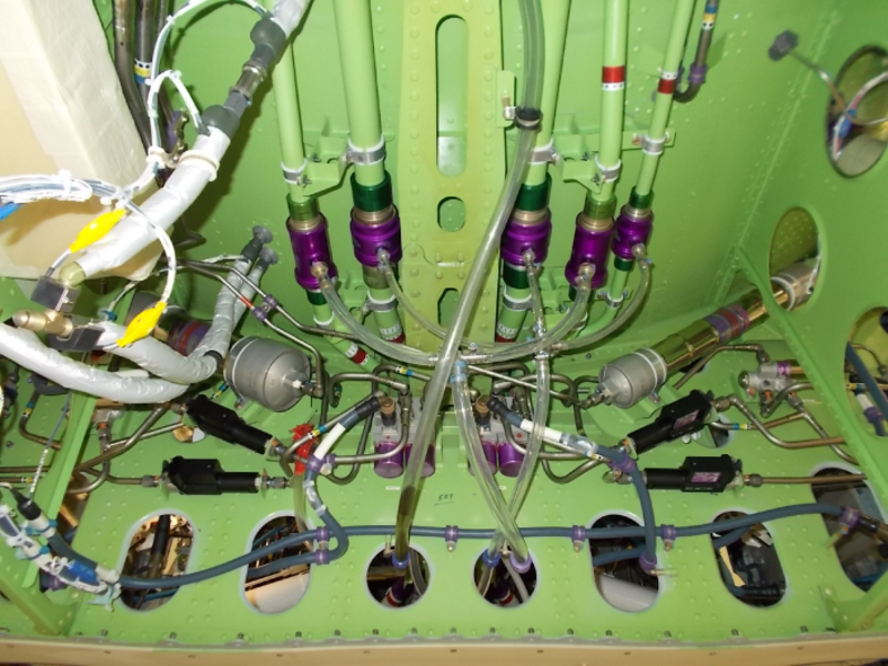
Two brake control valves are on the aft side of the underwing fairing support frame. Each control valve controls brake pressure at two wheels. One valve is connected to the inboard brake system and the other is connected to the outboard brake system.
Each brake control valve has a valve body with two slide and sleeve assemblies and two externally installed servo valves. Each servo valve has a torque motor and an electrical connector. The torque motor is an electromagnetic device that moves in proportion to the input of the electrical current. The movement of the torque motor controls internal hydraulic pressure in the brake control valve and sends this pressure through the brake ports to the brake units.
Each brake control valve has a pressure port, return port, and two brake ports. One brake port is for the left wheel and the other for the right wheel. The pressure port is connected to one outlet of the shutoff valve, which is between the brake pressure inlet and the control valve. The return port is connected to the system return line. The brake port is connected to a hydraulic fuse between the shuttle valve and the brake.
If the electrical current to the servo valve increases, it causes hydraulic pressure at the brake port to increase. The brake control unit increases and decreases electrical current to the servo valve to control brake pressure.


11/27/15
Brake Unit
There is a brake unit on each of the four MLG axles. Each brake unit is hydraulically operated from the left and right hydraulic systems. Each brake unit includes the following components:
Piston Housing
The aluminum piston housing has five adjusters, four hydraulic bleeder valves, and a quick-disconnect coupling. The piston housing is attached to the torque plate with eight bolts and washers. The piston housing, with the adjusters, does the actuation, retraction, and clearance adjustment functions of the brake unit.
Torque Plate
The steel torque plate holds and aligns the pressure plate, stator disks, and the end plate with the rotors.
Carbon Heat Sink
The carbon heat sink has all the parts that have friction surfaces which cause the brake unit to stop the turn of the wheel. Two wear indicator pins, which are attached to the pressure plate, extend through the piston housing to give a visual indication of heat sink wear.The carbon heat sink includes the components that follow:
Pressure Plate
The pressure plate has drive slots on the inner diameter that engage with lugs on the torque plate. The pressure plate does not turn, but moves as necessary on the torque plate while the brake unit operates.
Rotors
There are three rotors which have drive slots on the outer diameter that engage with drive lug inserts in the wheel base. Each drive slot has metal clips attached to the rotors to prevent wear. The rotors turn with the wheel, and move as necessary on the drive lug inserts of the wheel while the brake unit operates.
Stator Disks
There are two stator disks which have drive slots on the inner diameter that engage the lugs on the torque plate. The stator disks do not turn, but move on the torque plate as necessary while the brake unit operates.
End Plate
The end plate has two torque buttons that are attached to one side and engage holes in the torque plate. The end plate does not turn or move when the brake unit operates.
Brake Unit Operation
Hydraulic pressure in the piston housing pushes the five pistons against the pressure plate which causes the pressure plate to move. This causes the rotors, stator disks, and end plate to have decreased space between the pressure plate and the torque plate. The rotors, which turn with the wheel, are decreased in speed or stopped by friction against the pressure plate, stator disks, and end plate.
When the hydraulic pressure is released, the adjuster will push the pistons back to their initial position. This gives a constant clearance after each brake release.


Brake Pressure Transducer
Four brake pressure transducers are installed on the aft side of the under-wing fairing support frame. A pressure transducer is installed in each of the four brake lines between a hydraulic fuse and a shuttle valve. Each brake pressure transducer has one hydraulic port and one electrical connector. Each brake pressure transducer uses a resistor bridge configuration which changes the hydraulic pressure at the input port into an electrical signal. The transducers send these signals to the inboard and outboard circuit-cards of the brake control unit.


Brake Shuttle Valve
Four brake shuttle valves are installed in the MLG wheel well. One shuttle valve is installed in each of the brake pressure lines between the brake control valve and the brake unit. The brake shuttle valves isolate the brake control-system function from the emergency/parking brake-system function. The shuttle valve sends the higher of the two input pressures (brake control system/antiskid pressure or emergency/parking brake pressure) to the brake unit.


Brake Shutoff Valve
Two brake shutoff valves are installed on the aft side of the under-wing fairing support frame. Each shutoff valve is a single-coil, three-way, two-position, usually-closed solenoid valve. The valve has an electrical solenoid, a pressure port, a return port, and a cylinder port. Hydraulic flow is from the cylinder to return port in the de-energized position, and from pressure port to the cylinder in the energized position.
One shutoff valve is installed in the left hydraulic system and the other in the right hydraulic system. Each shutoff valve controls the hydraulic pressure to two brake control valves. If there is a hydraulic malfunction, the primary function of the shutoff valves is to isolate defective components. The second function is to stop hydraulic fluid flow to the brake control valves during flight.


Brake Check Valve
There are four brake check valves in the brake control system. They are installed in the MLG wheel well. Two check valves are installed in the left hydraulic system and two are installed in the right hydraulic system. One check valve is installed upstream of the accumulator in each hydraulic system pressure-line. The other is installed in each hydraulic system return-line. The check valves keep fluid flow in one direction in the hydraulic line.


10/10/19
Brake Hydraulic Fuse
The four brake hydraulic fuses are installed on the aft side of the under-wing fairing support frame. One hydraulic fuse connects to the brake port of each brake control valve, between the brake control-valve outlet and the brake inlet. The hydraulic fuse keeps fluid leakage to a minimum if there is damage to a line downstream of the brake control valve.
Each brake hydraulic fuse has one system port (connected to the brake control valve), one brake port (connected to the brake line), and a flow operated switch. The fuse has an automatic reset function that gives it a clean start in less than 5 seconds after a maximum of 5 psid (pressure differential). This occurs without the aid of hydraulic flow in the opposite direction. The automatic reset function is not possible after a pressure differential of 20 psid or more, but a manual reset is possible. The fuse has a manual bypass lever that is spring-loaded (to the usual closed position). This lets flow through the fuse unless the manual bypass lever is held in the open position. In the open position the manual bypass lever will let the brake control system be bled of air.


Brake Accumulator
There are two hydro-pneumatic accumulators that are found on the aft side of the under-wing fairing support frame. One is the brake accumulator is a piston type gas pressurized unit that has a volume of 50 in3 (819.35 cm3). The brake accumulator is pressurized with nitrogen to 500±25 psi (2,068.44 ±172.37 kPa). It is installed upstream of the brake shutoff valve in the right hydraulic system and contains pressurized hydraulic fluid. If the primary pressure source has a malfunction, the brake accumulator supplies emergency pressure to the outboard brake system.
The other accumulator is the emergency/parking brake accumulator. It is installed upstream of the brake shutoff valve in the left hydraulic system and contains pressurized hydraulic fluid. If the primary pressure source has a malfunction, the emergency/parking brake accumulator supplies emergency pressure to the inboard brake system.


Brake Pressure Switch
Two dual-pressure, hydro-mechanically operated brake pressure switches are installed on the aft side of the under-wing fairing support frame. One switch is connected to the left hydraulic system and the other to the right hydraulic system. Each is a two pole, two throw switch with a hydraulic fitting on one end and an electrical connector on the other end. The brake pressure switches are adjusted to open on increase pressure in the range of 1,875 to 2,025 PSIG and to close on decrease pressure in the range of 1,400 to 1,750 PSIG.
The brake control unit uses pressure switch signals to monitor hydraulic system pressure. The brake pressure switches signals are used to show the status of the brake accumulator (inboard brakes) and emergency/parking brake accumulator (outboard brake) on the EICAS and on the HYDRAULIC synoptic page.


03/09/26
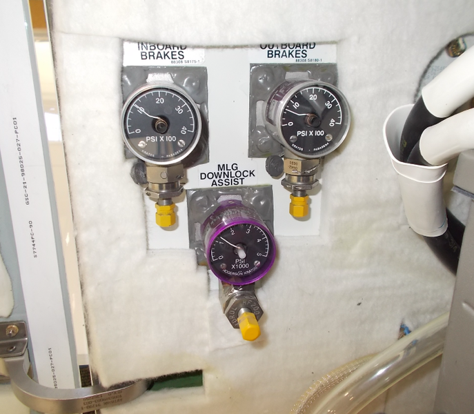
Brake Pressure Gauge and Charge Valve
The brake pressure gauge and charge valve is found on the FS635.00 bulkhead in the rear fuselage battery compartment. The gas side of the brake accumulator can be manually pressurized through the charge valve. The gauge shows the nitrogen gas pressure in the accumulator in psi. There are two brake pressure gauges and charge valves.
The gauge and valve mounted inboard position (outboard brake system) is for the brake accumulator in the right hydraulic system.
The gauge and valve mounted outboard position (inboard brake system) is for the emergency/parking brake accumulator in the left hydraulic system.

Wheel Speed Transducer
One wheel speed transducer is in the axle of each MLG wheel. Each transducer has an adapter with a rotor shaft and a coil assembly contained in a housing. The housing also has stationary teeth and bearings in which the rotor shaft turns. A drive coupling connects the transducer rotor shaft to the wheel hub cap.
While each wheel turns, the hub cap turns the drive-coupling of the wheel-speed transducer. When the teeth of the rotor move through the teeth of the stator, the magnetic fields increase and decrease. These magnetic field changes cause alternating current in the coil that goes to the brake control unit as a sine wave signal.


Hubcap
Each of the four aluminum hubcaps is connected to the wheel axles with three screws. The hubcaps have a drive coupling that connects to the rotor shaft of the wheel speed transducer. While the wheel and hubcap turns, the drive coupling turns the rotor shaft of the wheel speed transducer.

System Operation
The brake control system controls and operates the MLG brakes through a brake control unit, which has two circuit cards. Each brake control circuit card has a different electrical power source. The brake control unit receives 28 VDC electrical power from the L ESS BUS and the R ESS BUS. The inboard brake control is energized through the L ESS BUS through circuit breaker LDG GEAR INBD BRAKES (CB1-C15). The outboard brake control is energized by the R ESS BUS through circuit breaker LDG GEAR OUTBD BRAKES (CB2-C15).
The brake control unit circuit cards are the same but operate independently of each other. One circuit card controls the inboard wheel pair (2 and 3) and the other circuit card controls the outboard wheel pair (1 and 4). Each circuit card contains built-in test (BIT) logic for three types of tests. They are the power-up test (P-BIT), the continuous test (C-BIT), and the operator-initiated test (I-BIT).
The brake control unit receives data from the brake pedal transducers, wheel speed transducers, brake pressure transducers, and PSEU. Software on each circuit card changes the data into command signals. These signals then go to the brake control valve for brake pressure control and the SECU for spoiler/wheel spinup control. The signals also go to the FADEC for thrust reverser control.
The brake control unit, through the RDC , sends data to the EICAS, MDC, and FDR about the status of the brake system. It also does BITs of the brake control system components.
Operation During Takeoff and Landing
During taxi operations, the pilot can use the brakes to turn the aircraft. When the left pedal pressure is increased, the aircraft goes to the left. When the right pedal pressure is increased, the aircraft goes to the right. When the two pedals are pushed equally, the aircraft decreases speed in a straight line. Brake pedal movement controls the current that goes to the brake control valve. When the current to the brake control valve is increased, the brake port pressure is increased.
During take-off, anti-skid control logic occurs when the aircraft speed is more than15 kts. The logic circuit receives wheel velocity signals from each of the four wheel speed transducers and senses possible skids. If a skid condition is sensed for a wheel, the anti-skid logic command a decreased brake pressure to that wheel to prevent a skid.
Locked-wheel protection logic occurs when the aircraft speed is more than 30 kts. Locked-wheel protection logic compares the speed of each MLG wheel to the speed of its other wheel in a wheel pair. The pairs of wheels are numbers 1 and 4 (outboard pair), and numbers 2 and 3 (inboard pair). If the wheel speed in a pair is less than 33% of the other, the logic thinks that there is a locked-wheel condition. The logic will then tell the brake pressure to the slower wheel to decrease to zero to unlock it quickly. The pilot cannot use the brakes to turn the aircraft unless the slow wheel speed in a pair is more than 33% of the other.
The brake control system applies low brake pressure to stop the wheels during retraction of the MLG. Gear-retraction protection logic prevents the retraction of the MLG if the wheels are not stopped. The logic will command 350 psi (2, 413.16 kPa) brake pressure for 4 seconds in the conditions that follow:
- SQUAT=IN-FLIGHT, GEAR HANDLE=TRANSITION TO UP
- GEAR DOWN AND LOCKED=NOT LOCKED.
The brake control system makes sure that no brake pressure occurs during the touchdown. Touchdown protection logic prevents brake operation before the MLG wheels start to turn. The logic senses the SQUAT=GROUND condition from the MLG and spin-up speed from the wheel speed transducers. The touchdown protection logic lets brake operation start when the wheel speed is more than 50 kts or 5 seconds after the last touchdown. If the two MLGs go airborne before the 5 seconds after a touchdown occurs the time count starts again.
During landing, antiskid control logic occurs when the aircraft speed is above 10 kts. The logic circuit receives wheel velocity signals from each of the four wheel speed transducers and senses possible skids. If a skid condition is sensed for a wheel, the antiskid logic command a decreased brake pressure to that wheel to prevent a skid. The antiskid control logic does not occur if the wheel speed is below 10 kts (low-speed dropout). This low-speed dropout condition gives the pilot full brake-control to turn the aircraft with the brakes.
Pedal Control Function
The brake control unit uses the signal it receives from the inboard and outboard brake-pedal position-transducer LVDTs to calculate the brake pedal position. This brake pedal position is sent with hydraulic pressure and wheel-speed data to the brake control unit. The brake control unit then controls brake pressure through the brake control valves. The brake control unit also transmits the status data to the MDC through the ARINC 429 interface.
Antiskid Control Function
The antiskid function controls brake pressure to prevent skids. If a wheel starts to have a skid, the brake control system decreases the brake pressure sufficient to stop the skid. When the skid stops, the system increases the brake pressure again. This operation occurs very quickly, and the brake control system continues to monitor wheel speed and adjust brake pressure to runway conditions.
The brake control unit supplies an antiskid correction when the wheel speed is more than 15 kts. The software on the circuit-cards measures the speed of the wheel pairs continuously through sine waves transmitted by the wheel-speed transducers.
The circuit-card software receives data signals from the brake pressure and brake-pedal transducers, the pressure switches, and the PSEU. These data signals become control signals and are sent out to the SECU, the FADEC, and the brake control valves. This adjusts the aircraft braking to the runway conditions.
Through the ARINC 429 data bus, the brake control unit sends malfunctions and status data to the EICAS which has an interface with the MDC. These data are put through the MDC/EICAS to the RDC. The DCU then collects the data from the RDC and sends it to the FDR.
Pressure Control Function
Four brake pressure transducers supply brake pressure data to the brake control unit. Each of these transducers has a resistor bridge configuration which changes hydraulic pressure to the electrical signals that the brake control-unit circuit-cards use.
Two pressure switches monitor the available system pressure and supply the electrical signals to the related brake control-unit circuit-card. One pressure switch is connected to the left hydraulic system and the other to the right hydraulic system. Two shutoff valves control inlet hydraulic pressure to the brake control valves. The shutoff valves have two functions. The primary function is to isolate unserviceable hydraulic components. The second function is to turn off hydraulic power to the brake control valves during flight.
Four brake shuttle valves isolate brake control functions from emergency/parking brake functions. Each shuttle valve lets the higher value of the two input pressures (brake control/antiskid or emergency/parking brake) be applied, as necessary.
Four hydraulic fuses prevent the loss of hydraulic fluid from the brake system. Each fuse is installed between the brake control-valve outlet and the related brake inlet. This position will decrease the quantity of fluid that can go on a hot brake if a line is broken downstream of the fuse.
An accumulator is installed in each hydraulic system for emergency operation if there is a hydraulic malfunction. The right hydraulic system accumulator can supply sufficient hydraulic pressure for one brake operation with full antiskid function. The left hydraulic system accumulator can pressurize the parking brake for 12 hours or supply hydraulic pressure for six emergency stops. Two check valves are installed in each system. One isolates the accumulator from the hydraulic system, and one prevents return pressure flow that can occur in some hydraulic malfunctions.


11/27/15
Displays
The status of the brake accumulator is shown on the HYDRAULIC synoptic page of the EICAS. There is a box with the legend OUTBD BRAKES. This legend and the status in the box change color while the pressure in the accumulator changes as shown in the table.
| LEGEND (COLOR) |
STATUS (COLOR) |
CONDITION |
|---|---|---|
| OUTBD BRAKES (white) |
PRESS NORM (green) |
Not amber and not magenta |
| OUTBD BRAKES (amber) |
PRESS LOW (amber) |
Is amber until pressure increases to 1,875 - 2,025 psi. Becomes amber when pressure decreases to 1,750 - 1,400 psi |
| OUTBD BRAKES (magenta) |
PRESS ---- (magenta) |
Incorrect data |
For the status of the emergency/parking brake accumulator shown on the HYDRAULIC Synoptic Page of the EICAS (for the inboard brakes).
| LEGEND (COLOR) |
STATUS (COLOR) |
CONDITION |
|---|---|---|
| OUTBD BRAKES (white) |
PRESS NORM (green) |
Not amber and not magenta |
| OUTBD BRAKES (amber) |
PRESS LOW (amber) |
Is amber until pressure increases to 1,875 - 2,025 psi. Becomes amber when pressure decreases to 1,750 - 1,400 psi |
| OUTBD BRAKES (magenta) |
PRESS ---- (magenta) |
Incorrect data |
The EICAS messages that follow are related to the brake system:
| EICAS MESSAGE(S) | LEVEL (COLOR) |
|---|---|
| NORM BRAKES FAIL | WARNING (red) |
| CPLT BRAKE FAULT | CAUTION (amber) |
| L INBD BRAKE FAIL | CAUTION (amber) |
| R INBD BRAKE FAIL | CAUTION (amber) |
| INBD BRAKE PRESS LO |
CAUTION (amber) |
| INBD BRAKES FAIL | CAUTION (amber) |
| L OUTBD BRAKE FAIL |
CAUTION (amber) |
| R OUTBD BRAKE FAIL |
CAUTION (amber) |
| OUTBD BRAKE PRESS LO |
CAUTION (amber) |
| OUTBD BRAKES FAIL | CAUTION (amber) |
| PLT BRAKE FAULT | CAUTION (amber) |
| BRAKE FAULT | ADVISORY (cyan) |

11/27/15
System Interface
The brake control system has interfaces with the systems/components that follow:
- Spoiler Electronic Control Unit (SECU)
- Left and Right Hydraulic Systems
- Flight Data Recorder (FDR)
- Engine Indication and Crew Alerting System (EICAS)
- Data Concentrator Unit (DCU)
- Remote Data Concentrator (RDC)
- Proximity Sensor Electronic Unit (PSEU)
- Main Gear Extension and Retraction
- Parking Brake System
- Maintenance Diagnostic Computer (MDC)
- Full Authority Digital Engine Control (FADEC) System
10/20/20
Component Location Index
| Component Location Index | |||
|---|---|---|---|
| IDENT | DESCRIPTION | LOCATION | IPC REF |
| A67 | BRAKE CONTROL UNIT | ZONE(S) 221 | 32-43-01 |
| MT93 | BRAKE-PEDAL POSITION TRANSDUCER (LH) | ZONE(S) 211 | 32-43-05 |
| MT95 | BRAKE-PEDAL POSITION TRANSDUCER (LH) | ZONE(S) 211 | 32-43-05 |
| MT94 | BRAKE-PEDAL POSITION TRANSDUCER (RH) | ZONE(S) 212 | 32-43-05 |
| MT96 | BRAKE-PEDAL POSITION TRANSDUCER (RH) | ZONE(S) 212 | 32-43-05 |
| MPE23 | BRAKE CONTROL VALVE (LH) | ZONE(S) 182 | 32-43-09 |
| MPE24 | BRAKE CONTROL VALVE (RH) | ZONE(S) 182 | 32-43-09 |
| - | BRAKE UNIT (LH) | ZONE(S) 730 | 32-43-13 |
| - | BRAKE UNIT (RH) | ZONE(S) 740 | 32-43-13 |
| MT97 | BRAKE PRESSURE TRANSDUCER (LH) | ZONE(S) 182 | 32-43-17 |
| MT99 | BRAKE PRESSURE TRANSDUCER (LH) | ZONE(S) 182 | 32-43-17 |
| MT98 | BRAKE PRESSURE TRANSDUCER (RH) | ZONE(S) 182 | 32-43-17 |
| MT100 | BRAKE PRESSURE TRANSDUCER (RH) | ZONE(S) 182 | 32-43-17 |
| - | BRAKE SHUTTLE VALVE (LH) | ZONE(S) 171 | 32-43-21 |
| - | BRAKE SHUTTLE VALVE (RH) | ZONE(S) 172 | 32-43-21 |
| MPE28 | BRAKE SHUTOFF VALVE (RH) | ZONE(S) 182 | 32-43-25 |
| MPE27 | BRAKE SHUTOFF VALVE (LH) | ZONE(S) 182 | 32-43-25 |
| - | BRAKE CHECK VALVE (LH) | ZONE(S) 171 | 32-43-29 |
| - | BRAKE CHECK VALVE (RH) | ZONE(S) 172 | 32-43-29 |
| - | BRAKE HYDRAULIC FUSE | ZONE(S) 182 | 32-43-33 |
| - | BRAKE ACCUMULATOR | ZONE(S) 182 | 32-43-37 |
| - | BRAKE PRESSURE GAUGE AND CHARGE VALVE |
ZONE(S) 182 | 32-43-41 |
| S99 | BRAKE PRESSURE SWITCH (LH) | ZONE(S) 182 | 32-43-45 |
| S98 | BRAKE PRESSURE SWITCH (RH) | ZONE(S) 182 | 32-43-45 |
| MT89 | WHEEL SPEED TRANSDUCER (LH) | ZONE(S) 730 | 32-43-49 |
| MT91 | WHEEL SPEED TRANSDUCER (LH) | ZONE(S) 730 | 32-43-49 |
| MT90 | WHEEL SPEED TRANSDUCER (RH) | ZONE(S) 740 | 32-43-49 |
| MT92 | WHEEL SPEED TRANSDUCER (RH) | ZONE(S) 740 | 32-43-49 |
| - | HUB CAP (LH) | ZONE(S) 730 | 32-43-53 |
| - | HUB CAP (RH) | ZONE(S) 740 | 32-43-53 |