


11/10/25
Overview
The nose wheel steering control system controls and operates the nose wheel steering. The system is electrically controlled and hydraulically operated. Hydraulic pressure from the left hydraulic system operates the nose wheel steering.
The nose wheel can be turned 65° left or right from center with the hand wheel. It can also be turned 7° left or right from center with the left or right rudder pedal. The steering control system also decreases vibration from the nose wheel when the aircraft is operated on the ground.
To operate the nose wheel steering, the pilot turns the hand wheel in the flight compartment or pushes the rudder pedals. This sends electrical signals to the steering control unit (SCU). The SCU, through the steering manifold, sends hydraulic pressure to the steering actuator. The steering actuator turns the steering collar and torque links, which turn the nose landing gear (NLG) axle.
Feedback from the rotary variable transducer (RVT) is sent through the SCU to the hand wheel. This lets the pilot know that the NLG is turned. If the steering control system is disarmed or unserviceable, it continues to decrease vibration from the nose wheel.


Steering Control Unit
The SCU controls the position of the nose wheel steering. The SCU is installed in the flight compartment below the left console. It is electrically connected to the other components in the system. The SCU is a two channel system which can find and isolate the internal system and the external system malfunctions. If the SCU has a malfunction, the SCU will de-energize and have no effect on the other aircraft systems.
When the SCU receives a turn signal from the hand wheel or rudder pedals, the SCU will:
- Do a check to make sure that the NLG is in a weight-on-wheels (WOW) condition.
- Do a check to make sure that the NLG downlock is locked.
- Do a check to make sure that there is no system malfunction.
- Find the difference between the hand wheel or rudder pedal position and the nose wheel position.
- Send a signal to the steering manifold to send hydraulic pressure to turn the nose wheel left or right.
- Stop the hydraulic pressure when the feedback is sent to the SCU that the nose wheel has turned to the correct position.


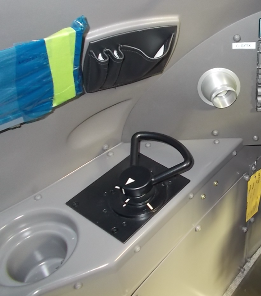
Steering Control Hand Wheel
The steering control hand wheel is in the flight compartment on the left console. It has a hand wheel, mounting plate, centering return spring, damper, and two single-channel potentiometers. Painted marks on the mounting plate show the center position and the maximum turn positions.
The shaft from the hand wheel goes through the damper. The centering spring and the damper give positive breakout force and feedback to the pilot. The centering spring turns the hand wheel back to the center position when it is released.
The two single-channel potentiometers are independently connected to the shaft. When the hand wheel turns, each of the potentiometers sends a signal to the SCU. The signal from one potentiometer is used as the steering control signal. The signal from the second potentiometer monitors the signal from the first.


Steering Selector Valve
The steering selector valve is on the right side of the NLG wheel well on the steering system pressure line. The SCU controls and monitors the steering selector valve. It is usually closed.
When the valve is de-energized, the steering system pressure line is connected to the left hydraulic system return line. When the valve is energized, the steering system pressure line is connected to the left hydraulic system supply line. A valve is spring-loaded to close when electrical power is removed.

Steering Manifold
The steering manifold is on the aft side of the NLG. It has an internal bypass valve and an external electro-hydraulic servo valve (EHSV). The steering manifold is controlled by the SCU to send hydraulic pressure to one of the two steering actuator cylinders. This moves the steering actuator in one of two directions and turns the nose wheel in the associated direction. The steering manifold consists of the bypass valve and the electro-hydraulic servo valve (EHSV).

Bypass Valve
The bypass valve is a two position sliding-spool valve. It is operated with left system hydraulic pressure. When there is no hydraulic pressure, the bypass valve spring will close the valve. The bypass valve opens or closes the steering actuator cylinder-ports to give free or pressurized flow. Hydraulic pressure moves the bypass valves which lets pressure go to one of the two steering actuator cylinders. With hydraulic pressure removed, the bypass valve spring moves the bypass valve to the free flow position. This connects the cylinder ports with the hydraulic system return-line to let the nose wheel turn freely.
Electro-hydraulic Servo Valve
The EHSV is a two stage, four way, flow-control valve. It is controlled and monitored by the SCU. The EHSV receives the signals from the SCU and sends hydraulic pressure to one side or the other of the bypass valve.
The EHSV has two coils, a dry-torque motor and a linear-variable differential transducer (LVDT) to sense the valve position. The servo valve has a second-stage spool-and-sleeve valve with a mechanical-feedback spring between the spool and the first-stage jet pipe. The LVDT, connected to the second stage spool, sends an electrical signal to the SCU to show the spool position. This electrical signal is used by the SCU to monitor the EHSV operation.

Steering Actuator
The steering actuator is a hydraulically operated rack that is installed on the NLG shock strut. The steering actuator is a part of the rack-and-pinion steering mechanism. It has a cylinder, two pistons and a rack.
For steering operation, hydraulic fluid will flow into one of the two ends of the cylinder and push one of the pistons. The piston will then push the rack. The rack has teeth that engage with the teeth on the steering body assembly pinion. This will transmit movement to the nose wheels through the torque links and axle.


Steering Compensator
The steering compensator is installed in the forward NLG bay on the left side. It is a spring-loaded piston-and-cylinder assembly, with a poppet valve S/A that maintains a minimum pressure of 70 psi (483 kPa) in the NLG steering manifold. This pressure helps shimmy damping and prevents cavitation in the system. Cavitation can occur when the NLG steering geometry changes. This can cause a negative pressure that causes air bubbles in the hydraulic fluid. The steering compensator assembly adjusts the negative pressure to prevent the air bubbles.
When there is sufficient pressure at the inlet port, the poppet valve S/A will move. The movement continues and opens the poppet valve. This allows fluid to flow through the valve and out of the outlet. When there is a decrease in the pressure at the inlet port, the piston moves the other way and continues until the poppet valve closes, and holds a known quantity of hydraulic fluid on the inlet side of the piston. The differential forces of the springs and the fluid pressure balance the piston and open and close the poppet valve when necessary.


Rudder Pedal Transducer
The rudder pedal transducer is attached to the rudder system main quadrant below the flight compartment floor. It has three single-channel potentiometers on one shaft. Two send electrical signals to the SCU, one for steering control and one to monitor the first signal. The other potentiometer sends electrical signals to the flight data recorder.
The maximum turn for potentiometers is ±23.3°. This gives a maximum turn of ±7° at the nose wheel. The rudder pedal transducer opens the circuit and disarms the steering if it is turned beyond this limit.
Rudder Pedal Transducer Coupling
The rudder pedal transducer-coupling connects the rudder pedal transducer to the rudder pedal quadrant-shaft. It is used to transmit the movement of the rudder quadrant to the input shaft of the transducer. Two self-locking cap screws attach the coupling to the flat part of each shaft. The cap screws have holes for lockwire.

Steering Pressure Switch
The steering pressure switch is installed on the right side of the nose-gear wheel well. It is in the steering system pressure-line downstream of the steering selector valve. The steering pressure switch is used to sense hydraulic pressure downstream of the selector valve. This will show if the steering system is in the pressurized or free-flow mode. The SCU monitors the position of the pressure switch and the selector valve to make sure of the mode that the steering system is in.
The steering pressure switch closes at a maximum pressure of 1,800 psi (12,410.64 kPa) and opens at a minimum pressure of 1,400 psi (9,652.72 kPa).

Rotary Variable Transducer
The rotary variable transducer (RVT) is installed on the aft side of the NLG. It is mechanically connected to the nose wheel position-feedback mechanism and electrically connected to the SCU. The RVT is used to give the SCU feedback data on the position of the nose wheel.
When the shaft of the RVT is turned, two signals are independently sent to the SCU. The first signal gives data on the position and movement of the nose wheel. The second signal is used to monitor the first. If the feedback mechanism is disconnected, a return spring on the RVT will move it back to the center position.

Oversteer Switch
The oversteer switch touches the indicator pins on the NLG at ±123° of nose wheel angle. At this angle, the pins break off. This shows that damage was possibly done to the WOW harness and the feedback linkage.


11/10/25
Operation
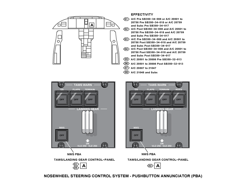
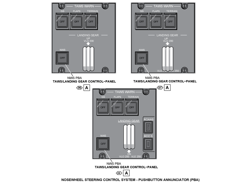
The NWS pushbutton annunciator (PBA) is found in the flight compartment on the main instrument panel. The pilot and copilot have access to the PBA. The NWS PBA is part of the TAWS/LANDING GEAR control panel. The NWS PBA is used to arm or disarm the nose wheel steering system. When the PBA is pushed, the pushbutton will come on with the annunciation OFF which shows that the steering system is disarmed. Also a NWS OFF status message will show on the EICAS. When the PBA is pushed again, the pushbutton annunciation will go off and the steering system is armed.
When the steering system is armed the SCU is energized. At this time a power built-in-test (PBIT) is done and the SCU senses if the nose wheels are more than ±65 degrees from the center. If this is sensed the SCU is deenergized. Also the steering selector valve will be deenergized until the nose wheels are moved back to less than ±65 degrees from the center. While the nose wheels are more than ±65 degrees from the center and until the SCU is set, a NWS FAIL message will show on the EICAS. When the nose wheels are moved back to less than ±65 degrees from the center and no malfunctions are found the NWS PBA can set the SCU.
The aircraft can be towed, with the torque links connected and the steering system de-energized. There is a limit of ±120 degrees of the nose wheel angle. If the nose wheel turns more ±120 degrees, the oversteer switch operates and a NWS LIMIT EXCEEDED caution message is shown on the EICAS.
The oversteer switch will touch the indicator pins on the NLG at ±123 degrees of the nose wheel angle. At this angle, the pins will break off. This will show that damage was possibly done to the WOW harness and the feedback linkage. The steering torque links can be disconnected for special hangar operation. With the torque links disconnected, there is no turn angle limit for the nose wheel, but the shock strut extension must be more than 2.35 in (59.69 mm).
For taxiing operations, the steering-control system will turn the nose wheel to a maximum of ±65 degrees from the center. The steering system has a limit of ±65 degrees from the center when the steering control hand wheel is used. The steering system has a limit of ±7 degrees from the center when the rudder pedals are used. If the steering control hand wheel is turned, a signal is sent from its potentiometer to the SCU. If a rudder pedal is pushed, a signal is sent from the rudder pedal transducer to the SCU.
For the steering system to operate, the conditions that follow are necessary:
- The NLG is down and locked
- The NLG is in a WOW condition
- No system faults are found by the SCU
- The nose wheel steering is ON
Note:
The SCU gets the NLG down and locked and the NLG WOW data from the PSEU.
When these conditions occur, the SCU energizes the steering selector valve and hydraulic pressure is sent to the steering bypass valve. This disconnects the cylinder ports from the return line and connects them to the EHSV pressure ports.
The SCU keeps the nose wheel in the center position until it gets a turn signal.
When the hand wheel or the rudder pedals are operated, the SCU gets a turn signal. The SCU then calculates the position error (hand wheel + Rudder Pedals − Feedback = Position Error). The position error signal is sent through the servo amplifier to the torque motor coils of the pressurized EHSV. The EHSV changes the signal into a movement of the spool which sends the hydraulic pressure to the correct side of the steering actuator piston. The actuator then turns the nose wheel to the correct position.
The SCU keeps an electrical current through the EHSV coils until the feedback RVT decreases the position error to zero. The zero position error moves the EHSV spool to the neutral position and the steering actuator movement is stopped. When the hand wheel or rudder pedals are moved to cancel the initial turn signal, a new position error occurs. The SCU again sends a signal to the EHSV coils until the actuator moves the nose wheels to cancel the position error.
During the take-off, steering control is automatically stopped when the WOW signal is gone. The turn signals are replaced by a straight ahead signal to make sure that the nose wheels are kept in the center position. Also, the centering cams in the NLG will engage and keep the nose wheel in the center position while the shock strut extends.
The SCU sends malfunction signals to the DCU which causes messages to show on the EICAS. The SCU causes a NWS FAIL caution message to show on EICAS when a malfunction is found. The SCU also causes a NWS FAULT advisory message to show on EICAS when the selector valve is locked in the open position.
The EICAS messages that follow are related to the nose wheel-steering control system:
| EICAS MESSAGE(S) | LEVEL (COLOR) |
|---|---|
| NWS FAIL | CAUTION (amber) |
| NWS LIMIT EXCEEDED | CAUTION (amber) |
| NWS FAULT | ADVISORY (cyan) |
| NWS OFF | STATUS (white) |
Also, the SCU malfunction codes are recorded into memory of the MDC. The LRU level fault-codes for the SCU are shown on the copilots multi-function display (MFD). This display helps the maintenance to be done easily and quickly.


11/30/15
System Interface
The nosewheel steering control system has interfaces with the system/components that follow:
- Left and Right Hydraulic Systems
- Data Concentrator Unit (DCU)
- Proximity Sensor Electronic Unit (PSEU)
- TAWS/LANDING GEAR Contol Panel
- Maintenance Diagnostic Computer (MDC)
10/20/20
Component Location Index
| Component Location Index | |||
|---|---|---|---|
| IDENT | DESCRIPTION | LOCATION | IPC REF |
| A73 | STEERING CONTROL UNIT | ZONE(S) 211 | 32-51-01 |
| MT85 | STEERING CONTROL HANDWHEEL | ZONE(S) 211 | 32-51-05 |
| V7 | STEERING SELECTOR VALVE | ZONE(S) 121 | 32-51-09 |
| - | STEERING MANIFOLD | ZONE(S) 710 | 32-51-13 |
| MT86 | RUDDER PEDAL TRANSDUCER | ZONE(S) 141 | 32-51-17 |
| S10 | STEERING PRESSURE SWITCH | ZONE(S) 121 | 32-51-25 |
| - | ROTARY VARIABLE TRANSDUCER | ZONE(S) 710 | 32-51-29 |
| - | RUDDER PEDAL TRANSDUCER COUPLING | ZONE(S) 141 | 32-51-33 |