


11/26/15
Overview
The function of the strobe lighting system is to give the aircraft position and direction in relation to other aircraft at a distance. The strobe light contains a white light (anticollision) for collision avoidance and a red light (beacon) for use on ground. The shape of the strobe lights is such as to minimize aerodynamic drag.
The lower strobe/beacon light is installed at the center belly fairing. The red flash tube is at the bottom of the light unit, and the white flash tube is at the top. The lower strobe/beacon light is controlled by the STROBE three-position switch on the LIGHTING control panel. The upper strobe/beacon light is installed at the top of the vertical stabilizer. The red flash tube is at the bottom of the light unit, and the white flash tube is at the top. The upper strobe/beacon light is controlled by the STROBE three-position switch on the LIGHTING control panel.
There are two strobe light power supplies which supply the necessary electrical power to the strobe/beacon lights. The strobe light power supply for the lower strobe/beacon light is installed in the center fuselage and the strobe light power supply for the upper strobe/beacon light is installed in the aft equipment compartment.
The strobe lights are controlled by the STROBE switch on the LIGHTING control panel.
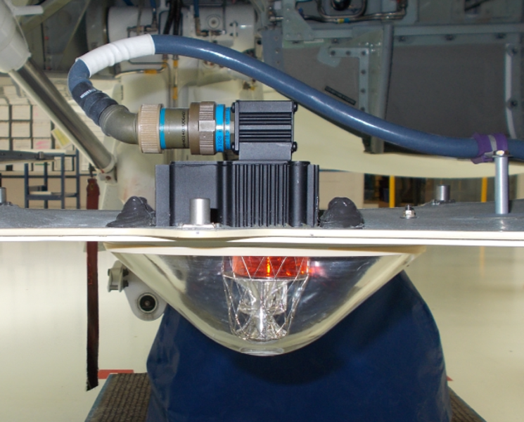
Lower Strobe/Beacon Light
The lower strobe/beacon light is at the center belly fairing. The lower strobe/beacon light is made of a light unit that uses two xenon flash tubes and a lens. The red flash tube is at the bottom of the light unit and the white flash tube is at the top. The lower strobe/beacon light is controlled by the STROBE three-position switch (STROBE, BCN, and OFF) on the LIGHTING control panel. The white light has a light intensity of 400 candles. The red light has a light intensity of 60 candles. The lower strobe/beacon light receives 400 VDC power from the applicable strobe light power supply.

Upper Strobe/Beacon Light
The upper strobe/beacon light is installed at the top of the vertical stabilizer. The upper strobe/beacon light is made of a light unit that uses two xenon flash tubes and a lens. The red flash tube is at the bottom of the light unit and the white flash tube is at the top. The upper strobe/beacon light is controlled by the STROBE three-position switch (STROBE, BCN, and OFF) on the LIGHTING control panel.
The white light has a light intensity of 400 candles. The red light has a light intensity of 60 candles. The upper strobe/beacon light receives 400 VDC power from the applicable strobe light power supply.

Strobe Light Power Supply
There are two strobe light power supplies which supply the necessary electrical power to the strobe/beacon lights. The strobe light power supply for the lower strobe/beacon light is in the center fuselage (at the junction of the aft fuselage) near the aft fuselage bulkhead on the left side at FS612.00. The strobe light power supply for the upper strobe/beacon light is in the aft equipment compartment on the right side at FS770.00 overhead.
The power supply provides approximately 400 VDC and an ignition pulse of 1.08 Hz. This 1.08 Hz signal is used on a connection between the two power supplies to make the lights flash at the same time. The strobe light power supplies receive 28 VDC power from the L MAIN BUS.


12/03/15
Wing-Tip Strobe Light (Post SB 350-33-004)
On post SB 350-33-004 the wing-tip strobe lights are installed at the left and the right wing tip. The wing-tip strobe lights are fitted with aperture assemblies to minimize the illumination reflection from the wing-tip strobe light within the wing tip lens. The wing-tip strobe lights will only flash in white. The wing-tip strobe lights are controlled by the STROBE three position switch (STROBE, BCN (beacon) and OFF) on the lighting control panel.
The wing-tip strobe lights receive 400 VDC from the strobe-light power supplies. The strobe-light power supplies are connected to 28 VDC R MAIN BUS.

11/26/15
Wing Strobe-Light Power Supply (Post SB 350-33-004)
On post SB 350-33-004 there are two strobe-light power supplies which supply the necessary electrical power to the left and the right wing-tip strobe lights. The left and the right strobe-lights power supplies supply approximately 400 VDC and an ignition pulse of 1 Hz. The left and the right strobe-light power supplies receive a synchronisation signal from the baseline lower strobe/beacon light power supply.
The left and the right strobe-light power supplies receive 28 VDC electrical power from the R MAIN BUS.

11/26/15
System Operation
The strobe lights are controlled by the STROBE switch on the LIGHTING control panel. The switch has three positions, STROBE, BCN and OFF. On pre SB 350-33-004 when the switch is in the STROBE position, the strobe lights will flash white. When the switch is in the BCN position, the strobe lights will flash red. On post SB 350-33-004 when the switch is in the STROBE position, the upper and the lower strobe/beacon lights and the left and the right wing strobe lights will flash white. When the switch is in the BCN position, the upper and the lower strobe/beacon lights will flash red. The left and the right wing strobe lights will go off. In the STROBE and BCN positions, the power supplies receive 28 VDC. In the BCN position, the RED/WHITE input of the power supplies is grounded and this sets the red lights to flash. In the STROBE position, the ground is removed from the RED/WHITE input of the power supplies and this sets the white lights to flash.
The flight crew will usually set the switch in the BCN (red light system) position for ground operation (as an alternative to the white anticollision light system). The red light system has less bad effects on vision of the flight crew or on personnel outside the aircraft during ground handling.


10/21/20
Component Location Index
| Component Location Index | |||
|---|---|---|---|
| IDENT | DESCRIPTION | LOCATION | IPC REF |
| DS20 | LOWER STROBE/BEACON LIGHT | ZONE(S) 182 | 33-43-01 |
| DS19 | UPPER STROBE/BEACON LIGHT | ZONE(S) 346 | 33-43-05 |
| DS47 | WING-TIP STROBE LIGHT (LH) (POST SB350-33-004) | ZONE(S) 541 | 33-43-07 |
| DS48 | WING-TIP STROBE LIGHT (RH) (POST SB350-33-004) | ZONE(S) 641 | 33-43-07 |
| PS1 | STROBE-LIGHT POWER SUPPLY | ZONE(S) 310 | 33-43-09 |
| PS2 | STROBE-LIGHT POWER SUPPLY | ZONE(S) 231 | 33-43-09 |
| PS9 | WING STROBE-LIGHT POWER SUPPLY (LH) (POST SB350-33-004) | ZONE(S) 541 | 33-43-13 |
| PS10 | WING STROBE-LIGHT POWER SUPPLY (RH) (POST SB350-33-004) | ZONE(S) 641 | 33-43-13 |