


12/17/15
Overview
The pitot-static and temperature system senses pitot pressure, static pressure, and external air temperatures. The pitot-static and temperature system supplies this data to air data computer (ADC) No. 1 and ADC No. 2. The ADCs calculate this air data and send it to the electronic flight-instrument system (EFIS) (pilot and copilot primary flight displays (PFD) and multi-function displays (MFD).
Error messages related to the pitot-static and temperature system are shown on the EICAS. A part of the pitot-static system also gives the data necessary for the integrated standby instrument (ISI).
Pitot Static Probes
There are two pitot static probes. They are at FS278.33 and WL106.30 on the left and right sides of the forward fuselage. The aircraft has pitot static probes made to agree to the AIRCRAFT aerodynamic parameters. They accurately sense pitot (total) and static (altitude) pressures for the full range of the aircraft. The pitot static probes send this data to the ADCs through solid pneumatic tubes and flexible hoses with quick-disconnect connectors.
To prevent ice on the pressure ports and incorrect pitot and static measurements, each pitot static probe contains two 28 VDC heaters with a hermetic seal. There is a heater for the head and strut and a heater for the baseplate. The left primary pitot static probe heaters receive 28 VDC electrical power from the L MAIN BUS through circuit breaker CB1-E2. The right primary pitot static probe heaters receive 28 VDC electrical power from the R MAIN BUS through circuit breaker CB2-E2.
Each primary pitot static probe also has two electrical connectors. The electrical connectors interface with the electrical power supply to the heaters. A drain hole removes moisture that collects in the total pressure circuit of the pitot static probes.
Pitot
Each primary pitot static probe has one pitot probe. It is identified as P1 for the left side and P2 for the right side. The pitot probe accurately senses the total pressures through the full range of the aircraft. An opening in the front of the probe senses total air pressure when the aircraft is in flight. The shape of this opening decreases the sensitivity of the tube axis slope to the airflow angles that constantly change.
The result is a total pressure measurement that is constant through the full angle-of-attack (AOA) and sideslip envelope.
Static
Each pitot static probe has two static pressure ports. The two static pressure ports are identified the same for the left and right pitot static probes. They are identified as S1 and S2. They are found on the side of reach pitot static probe tube. The static pressure ports give the static (altitude) pressures for the full range of the aircraft.
Because of the sideslip angle, the static pressure ports send their static pressure signals to the S1/S2 manifold that is internal to the manifold at FS250.00 (forward of the center instrument panel). The S1/S2 manifold keeps the errors in the signal values to a minimum and gives an averaged signal value to the ADCs.
ADCs
The left pitot-static probe S1 and the right static-probe S2 are connected to the ADC No. 1. The left pitot-static probe S2 and the right static-probe S1 are connected to the ADC No. 2.


02/14/17
Standby Pitot Probe
There is only one standby pitot probe. It is at FS301.30 and WL106.30 on the left side of the forward fuselage and only connected to the ISI. It is identified as P3.
The aircraft has a standby pitot probe made to agree to the aircraft aerodynamic parameters of the aircraft. The standby pitot probe accurately senses pitot (total) pressure through the full range of the aircraft. An opening in the front of the probe senses total air pressure when the aircraft is in flight. The shape of this opening decreases the sensitivity of the tube axis slope to the airflow angles that constantly change. The result is a total pressure measurement that is constant through the full AOA and sideslip envelope. The standby pitot probe sends its total pressure signal directly to the ISI.
A flexible hose with a quick-disconnect attaches the input from the standby pitot probe to the pitot pressure port of the ISI. To prevent ice on the pressure port and incorrect pitot measurements, the probe contains a 28 VDC heater with a hermetic seal for the head and strut.
The standby pitot probe heater receives 28 VDC electrical power from the R ESS BUS through circuit breaker CB2-E3. The standby pitot probe heater is controlled by the right air data sensor heater current monitor only.
The standby pitot probe also has an electrical connector. The electrical connector is the interface for electrical power to the heater. Moisture that collects in the tube of the total pressure circuit is removed through a drain hole.


S3 Static Ports
There are two S3 static ports and they are only connected to the ISI. They are identified as the left S3 static port and the right S3 static port. The left S3 static port is at FS334.40 and WL82.10 on the left side of the forward fuselage. The right S3 static port is at FS334.40 and WL82.10 on the right side of the forward fuselage.
The S3 static ports give the static (altitude) pressures for the full range of the aircraft. Because of the sideslip angle, the two static pressure ports send their static pressure signals to the S3 manifold that is also internally installed in the manifold at FS250.00 (forward of the center instrument panel). The S3 manifold keeps the errors in the signal values to a minimum and gives an averaged signal value to the ISI.
A flexible hose with a quick-disconnect connector connects the input from the S3 static ports to the static pressure port of the ISI.
To prevent ice and incorrect static measurements, each S3 static port has one 28 VDC heater. The left S3 static port heater receives 28 VDC electrical power from the L ESS BUS through circuit breaker CB1-E3. The right S3 static port heater receives 28 VDC electrical power from the R ESS BUS through circuit breaker CB2-E4. Each S3 static port uses two electrical splices to interface the supply of electrical power to its heater.
There are no drain holes for the S3 static ports. The moisture from the left and right S3 static ports are sent to the pitot static visual drain system.


Pitot Static Visual Drains
The pitot static system uses 10 pitot static visual drains to collect moisture and contamination from different system pneumatic tubes.
The pitot static visual drains are below the flight compartment floor on the left and right sides of the aircraft. They are between FS258.00 and FS266.45, and WL79.00.
Each pitot static visual drain has a quick-disconnect connector and a sight glass and float ball to help in visual inspections. Maintenance personnel remove the moisture and contamination in the pitot static visual drains at scheduled intervals.

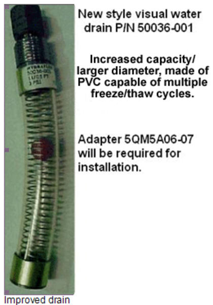
Optional SB 350-34-005 offers an increased capacity water accumulator assembly (drain) for the P1 and P2 pitot static system. The length of the new water accumulator assembly is the same as the old one, but its capacity is increased from 8.5 cc to 22 cc because of a larger inner diameter. Also, the new water accumulator assembly is made of PVC and is capable of multiple freeze/thaw cycles (if frozen when completely full, the tube diameter expands, but recovers when thawed).
Total Air Temperature Probe
There is one total air temperature (TAT) probe. It is at FS315.50 and WL120.00 on the right side of the forward fuselage.
An opening and air inlet scoop in the front of the TAT probe lets air flow through and around the sensing elements. There are different air exit ports at the rear of the housing that allow air go out. There is also an internal opening in the TAT probe. The internal opening prevents unwanted particles from collecting around the sensing elements. The sensed air temperatures are sent to the ADCs as resistance values.
The TAT probe senses external air temperature through two platinum sensing elements. The two sensing elements have a resistance of 500 Ohms at 32 °F (0 °C). The TAT probe has a thermal coefficient of 0.00385 W at 32 °F (0 °C). The TAT probe temperature measurement range is –148 to 662 °F (–100 to 350 °C).
Inside the housing of the sensors there is a 28 VDC heater. The heater keeps the two sensing elements free of ice in flight and on the ground.
When the aircraft is weight-off-wheels (WOFW), the TAT probe heater receives 28 VDC electrical power from the L MAIN BUS through circuit breaker CB1-E4 and is controlled by the left air data sensor heater current monitor only.
When the aircraft is weight-on-wheels (WOW), the TAT probe heater is inhibited with the TAT WOW output of the PSEU and the TAT WOW relay in the left secondary power center (LSPC). These components prevent operation of the TAT probe heater when the aircraft is WOW. The TAT WOW relay receives 28 VDC electrical power from the L ESS BUS through circuit breaker CB1-E1 from junction box JB3. The circuit breaker CB1-E1 also gives 28 VDC electrical power to the left air data sensor heater current monitor from junction box JB3.
The TAT WOW output of the PSEU controls the TAT WOW relay in the LSPC when it senses a weight-on-wheels signal. The TAT WOW relay in the LSPC removes the electrical power from the TAT probe heater when it receives the TAT WOW output from the PSEU.
There is a built-in airbump inside the TAT probe. The airbump removes the hot air caused by the heater from the surfaces of the housing. This reduces errors in TAT probe measurements.
The TAT probe has an electrical connector. The electrical connector is the interface for the TAT data and the ADCs and also electrical power to the heater.
The ADCs receive and calculate the TAT probe resistance values to show as different related data on the pilot and copilot PFDs and MFDs.


11/28/15
Operation
Pitot Static Probes
ADC No. 1 and ADC No. 2 use pitot (P1 and P2), averaged static (S1 and S2), and temperature inputs (TAT) from the pitot static and temperature system to calculate air data. The ADCs also have a static-source error function that corrects errors in the static system. The reason for the static-source error function is because all the static pressure signals are sent to one manifold. The manifold is forward of the center instrument panel at FS250.00. Inside this manifold there are two different manifolds. There is one for S1 and S2 and one for S3 (standby system). This manifold keeps the errors in the signal values to a minimum, but only gives an averaged signal value.
The ADCs receive pitot and static air pressure inputs from the left and right pitot static probes and sensed temperatures from the TAT probe. They calculate this data and send it to the IRS, EFIS, IAPS, and the SPS on ARINC 429 high-speed and low-speed buses. The ADCs show the different data as follows on the pilot and copilot PFDs and MFDs:
- Air speed indicator (ASI)
- Altimeter
- Ground speed (GS)
- International static atmosphere (ISA)
- Mach number
- Static air temperature (SAT)
- True airspeed (TAS)
- Vertical speed indicator (VSI)
- Wind speed and direction


Probe and Port Heater Control and Monitoring
The pitot static and temperature system probes and ports heaters receive electrical current and monitoring from the left and right air data sensor heater current monitors. The left air data sensor heater current monitor receives 28 VDC from the L ESS BUS via circuit breaker CB1-E1 through JB3. The right air data sensor heater current monitor receives 28 VDC from the R ESS BUS through circuit breaker CB2-E1.
The electrical current to the heaters of these probes and ports is controlled on or off with the PROBES L and PROBES R pushbutton annunciators (PBAs) from the ANTI-ICE control panel.
The current to the TAT heater is also controlled off by the following components:
- TAT weight-on-wheels (WOW) relay (in the left secondary power center [LSPC])
- PSEU
- JB3
The PSEU controls the TAT WOW relay in the LSPC when it senses a WOW signal. The TAT WOW relay in the LSPC removes electrical power from the TAT probe heater when output from the PSEU is received. When this occurs, the left air data sensor heater current monitor senses that there is a failure of the TAT probe heater. But, because there is no failure with the heater, the DCU inhibits a failure message on the EICAS.
A thermostat is not necessary for the heaters of the probes and ports because their electrical current draw is internally controlled. More electrical current draw is necessary when the temperature is low (in flight). Less electrical current draw is necessary when the temperature is high (on the ground).
In usual operation, the air data sensor heater current monitors control the electrical current to the heaters in the probes and ports.
In a failure condition, the related air data sensor heater current monitor prevents the supply of electrical current to the defective probe or port heater.
The air-data-sensor heater-current monitors control and monitor the electrical current to the heaters in the probes and ports that follow:
- Left Pitot-Static Probe
- Right Pitot-Static Probe
- Left S3 Static Port
- Right S3 Static Port
- Standby Pitot Probe
- TAT Probe
Standby System
The standby pitot probe (P3) and the left and right S3 static ports are used for the operation of the ISI. The standby pitot probe sends its total pressure directly to the ISI. The S3 static pressure ports give the static (altitude) pressures for the full range of the aircraft to the ISI. The S3 static pressure ports send their static pressure signals to the S3 manifold that is internally installed in the manifold (found forward of the center instrument panel at FS250.00) before they are sent to the ISI.
The ISI uses internal units to measure the total pressure from the standby pitot probe and static pressure from the S3 static pressure ports. The measurements calculate and show the following data on the ISI display panel:
- Airspeed
- Altitude
- Mach number

11/28/15
System Interface
The pitot-static and temperature system has interfaces with the systems and components that follow:
- Left Secondary Power Center (LSPC)
- Junction Box JB3
- Stall Protection System (SPS)
- Air Data Sensor Heater Current Monitor
- Engine Indication and Crew Alerting System (EICAS)
- Integrated Avionics Processor System (IAPS)
- SYSTEMS TEST Control Panel
- Electronic Flight Instrument System (EFIS)
- Proximity Sensor Electronic Unit (PSEU)
- Integrated Standby Instrument (ISI)
- Air Data Computer (ADC)
- Inertial Reference System (IRS)

03/30/22
System Test
Air Data System Probes
A test can be done with the SYSTEMS TEST control panel. When the rotary switch is set to PROBES and pushed, it starts a pilot initiated test (PIT). The primary function of the PIT is to ensure all discrete status outputs of the air data sensor heater current monitors operate correctly. The other types of built-in tests (BITs) do not check these outputs.
When the PIT is started, the air data sensor heater current monitors change all outputs from the correct condition to a fail condition and then back to the correct condition. During the test, EICAS failure messages must not show. At the end of the test, the white status message PROBE HEAT TEST OK message shows on the EICAS. This indicates the test is complete and correct.
The remote data concentrator (RDC) ensures the test sequence occurs. The air data sensor heater current monitors give a system failure status to the RDC. This data is then sent to the data concentrator unit (DCU) which signals for EICAS messages.
The EICAS messages display displays the related messages for the pitot static and temperature system:
- L PITOT HEAT FAIL – Caution message shows when the heater for the head and strut or the heater for the baseplate of the left pitot static probe has failed.
- R PITOT HEAT FAIL – Caution message shows when the heater for the head and strut or the heater for the baseplate of the right pitot static probe has failed.
- L PROBE HEAT OFF – Caution message shows when the heaters controlled by the L PROBE PBA on the ANTI-ICE control panel is off (not pushed).
- R PROBE HEAT OFF – Caution message shows when the heaters controlled by the R PROBE PBA on the ANTI-ICE control panel is off (not pushed).
- STBY PITOT HT FAIL – Caution message shows when the heater in the standby pitot probe has failed.
- L STBY STAT HT FAIL – Caution message shows when the heater in the left S3 static port has failed.
- R STBY STAT HT FAIL – Caution message shows when the heater in the right S3 static port has failed.
- TAT HEAT FAIL – Advisory message shows when the heater in the TAT probe has failed.
- PROBE HEAT TEST OK – Status message shows when the pilot initiated probe heat test is satisfactory.
The EICAS messages that follow are related to the pitot-static and temperature system:
| EICAS MESSAGE(S) | LEVEL (COLOR) |
|---|---|
| L PITOT HEAT FAIL | CAUTION (amber) |
| R PITOT HEAT FAIL | CAUTION (amber) |
| L PROBE HEAT OFF | CAUTION (amber) |
| R PROBE HEAT OFF | CAUTION (amber) |
| STBY PITOT HT FAIL | CAUTION (amber) |
| L STBY STAT HT FAIL | CAUTION (amber) |
| R STBY STAT HT FAIL | CAUTION (amber) |
| TAT HEAT FAIL | ADVISORY (cyan) |
| PROBE HEAT TEST OK | STATUS (white) |

10/20/20
Component Location Index
| Component Location Index | |||
|---|---|---|---|
| IDENT | DESCRIPTION | LOCATION | IPC REF |
| A137 | PITOT-STATIC PROBE (LH) | ZONE(S) 211 | 34-11-01 |
| A138 | PITOT-STATIC PROBE (RH) | ZONE(S) 212 | 34-11-01 |
| A143 | STANDBY PITOT PROBE (LH) | ZONE(S) 211 | 34-11-03 |
| A139 | S3 STATIC PORT (LH) | ZONE(S) 211 | 34-11-05 |
| A140 | S3 STATIC PORT (RH) | ZONE(S) 212 | 34-11-05 |
| - | PITOT-STATIC VISUAL DRAIN (LH) | ZONE(S) 211 | 34-11-09 |
| - | PITOT-STATIC VISUAL DRAIN (RH) | ZONE(S) 212 | 34-11-09 |
| A16 | TOTAL AIR TEMPERATURE (TAT) PROBE (RH) | ZONE(S) 212 | 34-11-13 |