


Overview
The standby air-data system is an auxiliary display that supplies the flight crew with the following aircraft data:
- Attitude
- Altitude
- Airspeed
- Maximum operating velocity (VMO)
- Instrument landing system (ILS) deviations
- Lateral acceleration indications
- Barometric correction pressure
- Mach number
The standby air-data system shows the data on the integrated standby instrument (ISI) installed in the main instrument panel. The standby air-data system uses inputs from the pitot-static and temperature system and the VHF navigation system to supply the ISI display. It also sends an ISI output signal to the stall protection system (SPS) and to the engine indication and crew alerting system (EICAS).
An ISI battery supplies power automatically to the ISI if the primary aircraft power supply fails. The ISI battery can supply power to the ISI for up to 5.2 hr.
Note:
SB 350-34-006 provides modification of the ISI to enable metric altitude display.
06/08/18
Integrated Standby Instrument
The integrated standby instrument (ISI) is in the center of the main instrument panel, between MFD No. 1 and MFD No. 2. The ISI is a self-contained unit that includes pressure sensors, inertial components, and electronic components. The ISI unit is clamp-installed in the ISI mount that attaches to the main instrument panel with four captive screws.
On the rear side, the ISI has one electrical connector and two pressure ports. The electrical connector supplies an interface for the input/output signals from/to other aircraft electrical systems. The pressure ports connect to the lines from the static ports and the standby pitot probe. The pressure ports have inlet filters and water traps to ensure that dust and humidity do not go into the ISI unit.
On the front, the ISI has a display panel and a bezel. The display panel shows the different ISI data. The bezel has one rotary switch (BARO) and four pushbuttons (CAGE, STD, BRT, and DIM), used to control the ISI operation as follows:
- CAGE pushbutton sets the gyroscope (gyro) to a cage condition
- BARO rotary switch sets the barometric (BARO) correction pressure
- STD pushbutton sets the barometric pressure to the standard (STD) pressure reference value (29.92 inHg/1013 hPa (hecto Pascal))
- BRT and DIM pushbuttons increase or decrease the lighting intensity of the ISI display.
The ISI is made so that effects of electromagnetic interference are reduced. To obtain the necessary interference reduction, metallic shields and electromagnetic interference (EMI) filters are used.
The ISI internal units measure the rotation speed and acceleration of the aircraft, and the total and static pressure. These measurements are used by the ISI to calculate and show altitude, airspeed, Mach number, and attitude (pitch and roll) data.
The ISI output data shows on the ISI display panel. The ISI data is also sent to other aircraft systems, on low-speed (LS) ARINC 429 data bus.
In usual conditions, the ISI is energized with 28 VDC from the R ESS BUS.
In emergency conditions when there is a power failure condition, the ISI is automatically supplied by the ISI battery.
The ISI display lighting is controlled with 0/28 VDC power from the lamp dimmer power supply No. 1.
The ISI bezel lighting is controlled with 0/5 VDC power supplied from the integral lighting controller.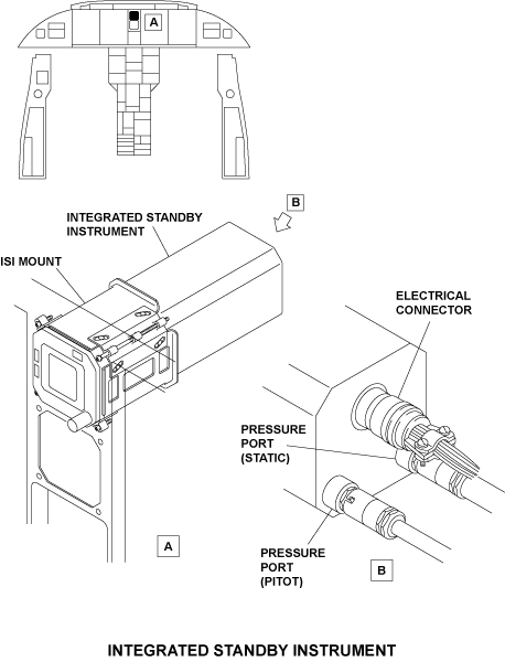
11/30/15
Operation
ISI Functions
The integrated standby instrument (ISI) supplies the flight crew with the following functions:
- Attitude display
- Altitude display
- Airspeed display
- Mach number indication
- Lateral acceleration indication
- Glideslope and localizer deviation indications
- Static source error correction (SSEC) indication
- Maximum operating velocity (VMO) indication
- Barometric correction pressure in hecto Pascal (hPa) and inches of mercury (inHg) indication
The ISI functions are supplied by the following primary internal units:
Inertial measurement unit (IMU)
The IMU measures rotation speed and acceleration of the aircraft to calculate and show the attitude (pitch and roll).
The IMU includes three rate gyro sensors and two accelerometers, together with their related temperature sensors. The IMU also includes the necessary electronic circuits that supply data in digital format.
Pressure measurement unit (PMU)
The PMU measures the total and static pressure to calculate altitude and indicated airspeed (IAS). The PMU includes two solid-state pressure transducers. Each transducer gives frequency coded signals that are measured with the use of built-in precision meters.
Memory and Processor Circuits
The memory and processor circuits keep and use different constant values, calibration parameters, and reference tables, together with the necessary interpolation algorithms.
Data used by the ISI includes altitude-pressure, baro correction, SSEC, and VMO tables. It also includes cockpit panel tilt-angle values, indicated airspeed and Mach number tables, lighting intensity control law, and optical parameters.
Static Source Error Correction (SSEC)
The speed of the aircraft induces an error into the static pressure system as a result of airflow disturbances around the static sensing port. This error is called static source error (SSE).
The SSE changes with speed, altitude, and angle of attack. To adjust for this error, the ISI has SSEC function that calculates pressure, altitude, and Mach number data. The SSEC is specific to the aircraft and its value is a function of a number of parameters. When the SSEC cannot be calculated, the ISI display shows an SSEC caution message.
Modes of Operation
The ISI operates in different modes in relation to the configuration selection that is set through discrete inputs (pin programming) to the ISI, and also in relation to its operating conditions. The primary ISI modes of operation are as follows:
Initialization Mode
On power-up, the ISI starts the initialization mode. This mode includes activation of hardware, software, and sensor initialization and stabilization. During sensor stabilization, ALIGNING annunciation shows on the ISI.
The initialization mode also includes a power-up built-in test (PBIT) sequence.
The PBIT does a check for ISI conditions before the ISI starts its functions. If one of the ISI functions has a fail condition, applicable warning messages show on the ISI display.
Operational (Inflight) Mode
The operational mode is the usual mode of operation of the ISI. This is the only mode that can be on while the aircraft is in flight. When the ISI operates in this mode and in usual conditions, it supplies all its functions.
If there is a fail condition in one of the ISI functions, an applicable warning flag shows on the ISI display. When the fail condition occurs in the airspeed function, the SSEC correction is no longer used in the calculation of altitude and a caution SSEC yellow flag shows on the ISI display. In this condition, the ISI supplies only the pitot static data.
Also, when the ISI power supply is lost for more than 50 ms, the ISI switches to a low-power mode. If power is lost for up to 200 ms max, the ISI continues to operate but with its graphics function inhibited. In this condition, the ISI goes back to the full operational mode when power becomes available again. However, if the power is lost for more than 200 ms, the ISI operation stops completely.
Maintenance Mode
The maintenance mode shows maintenance data on the ISI display. The ISI is put into this mode when the PBIT is complete and the input discretes are set to the maintenance mode configuration. Data shown in the maintenance mode include the aircraft configuration data, test results, and fault codes.
Simulation Mode
The simulation mode is used during shop maintenance to supply the ISI with simulation signals for fault isolation.
In the simulation mode, the different inflight mode functions can be simulated.
Note:
The maintenance and simulation modes cannot be on if the aircraft calculated airspeed (CAS) is more than 50 kt.


Controls and Displays
ISI Controls
ISI Power Control
The flight crew can set the ISI battery function on or off with a pushbutton annunciator (PBA) on the ELECTRICAL control panel. This pushbutton annunciator (STBY INST) has a black OFF legend. In usual conditions, the ISI battery system is on and the light of the STBY INST PBA is off.
When the flight crew pushes the STBY INST PBA, the PBA light comes on to show that the ISI battery system is OFF. If the STBY INST PBA is pushed again, the PBA light extinguishes. In this condition the ISI battery system is active.
ISI Operation Controls
The integrated system instrument is controlled by the flight crew with one rotary switch (BARO) and four pushbuttons (STD, CAGE, BRT, and DIM).
- The BARO button allows the flight crew to set the barometric correction pressure. When the BARO button is turned clockwise, the pressure value increases. When the BARO button is turned counterclockwise, the pressure value decreases.
- The STD pushbutton is pushed to set the pressure to the standard value (29.92 inHg/1013 hPa).
- The CAGE pushbutton is pushed (for at least two seconds) to make sure that the horizontal line aligns with the center dot and the slip/skid indicator aligns with the center position. Pushing the CAGE pushbutton shows a CAGE annunciation on the ISI display. The CAGE function is only used when flight conditions are stable (low pitch and roll angles and stable airspeed).
- Pushing the BRT or DIM pushbutton increases or decreases the lighting intensity of the ISI display (the average lighting level is set with the ANNUN-BRT/DIM switch on the COCKPIT LIGHTS control panel).
ISI Displays
On power-up, ALIGNING annunciation shows on the ISI display. After the initialization mode, the ISI shows the different ISI data.
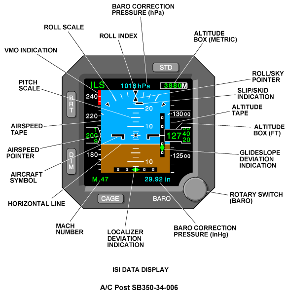
Attitude Display
Attitude data shows in the center area of the ISI display panel with symbols that move in relation to fixed symbols. All symbols are shown on a sky-earth (blue and brown) background. The symbols that move include:
- White horizontal line
- Pitch scale
- Roll/sky pointer
The fixed symbols include:
- Aircraft symbol (nose and wings)
- Roll scale
- Roll indexes
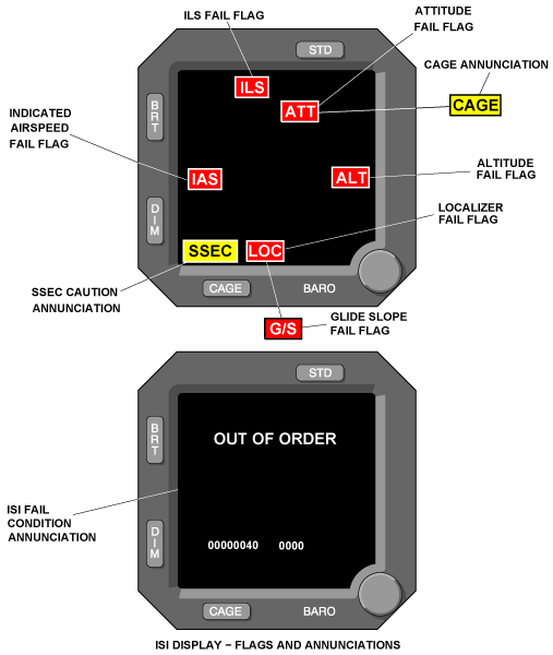
When there is an attitude fail condition, the blue and brown background, pitch and roll scales, and roll/sky pointer are removed from the display and an ATT red flag is displayed to the flight crew.
Slip-Skid Indication
Slip-skid data shows below the roll/sky pointer. It shows as a trapezoidal symbol that moves left or right in relation to the roll/sky pointer and as function of the lateral acceleration.
ILS Deviation Indications
When the ILS receiver is tuned to a correct ILS frequency, a green ILS annunciation shows at the top of the ISI display.
In usual condition, the ILS deviation data shows on the ISI with a localizer deviation indication and a glideslope deviation indication.
The localizer deviation indication shows in the bottom area of the sky/earth background. It uses a diamond pointer that moves against a horizontal scale. The scale has square deviation dots and a center dash. The localizer scale range is ±0.19 difference in depth of modulation (DDM). The second dots are at ±0.16 DDM.
The glideslope deviation indication shows to the right of the aircraft nose/wings symbol. It uses a diamond pointer that moves against a vertical scale. The scale has square deviation dots and a center dash. The glideslope scale range is ±2.10 DDM. The second dots are at ±0.18 DDM.
If there is a localizer or glideslope fail condition, the applicable LOC or G/S scales and pointers are removed form the display. In this condition, an applicable LOC or G/S red flag is displayed to the flight crew.
If there is an ILS fail condition, the ILS annunciation changes to an ILS red flag and the two deviation scales and pointers are removed from the display.
When the ILS receiver is not tuned to an ILS frequency, ILS data is removed from the display and there is no flag display.
Altitude Display
Altitude data shows on the right side with an altitude tape that moves up and down against a fixed altitude box. The altitude box contains a counter that shows the ten-thousands and thousands feet in 20-ft increments.
The altitude tape has graduations every 100 ft and a numerical indication every 500 ft. Also on the altitude tape, each 1000-ft numerical indication is shown between two white lines.
Note:
On A/C Post SB 350-34-006, the ISI metric version has an altitude box (Meters) in the top right corner below the STD pushbutton. Altitude in meter information is calculated from the baro-corrected altitude in feet through a 0.3048 meter-to-feet factor.
When there is an altitude fail condition, the altitude scale is removed from the display and an ALT red flag shows to the flight crew.
Baro Correction Pressure
The ISI shows the baro correction pressure in inHg (below the altitude tape) and in hPa (at the top of the altitude tape). There is no warning message for the baro correction function.
Airspeed Display
Airspeed data shows on the left side with an airspeed tape that moves up and down. The tape has graduations every 5 kt between 40 and 250 kt; and every 10 kt after. A numerical indication is added every 20 kt. Airspeed indication is given by a pointer. The pointer is white with a trapezium shape.
When there is an airspeed fail condition, the airspeed tape and pointer are removed from display and an IAS red flag is displayed to the flight crew.
Mach Number Indication
Mach number shows below the airspeed display tape. It shows with an M symbol before a decimal point and a two-digit indication. Mach number indication is usually green. It changes to red in relation to the calculated airspeed and the VMO.
VMO Indication
VMO indication shows as a red band on the airspeed tape. The VMO indication shows only for VMO and more than VMO values. When the calculated airspeed is greater than VMO, the Mach number display changes from green to red. The Mach number shows again in green when the airspeed is less than VMO-2 kt ±1 kt.
SSEC Annunciation
SSEC annunciation is a caution message that shows at the bottom and left side. The annunciation tells the flight crew that the static source error correction (SSEC) cannot be calculated.

System Interface
The integrated standby instrument (ISI) interfaces with other aircraft components/systems for the following functions:
- Receive inputs from the pitot static ports and the standby pitot probe
- Receive an input from the instrument landing system (ILS)
- Send and receive data to/from the stall protection computer (SPC)
- Supply air data to the DCU (and then to the flight data recorder [FDR], in emergency mode)
- Get the necessary electrical power to energize the ISI circuits
- Receive (through the COCKPIT LIGHTS control panel) electrical power that controls the ISI display lighting and the ISI bezel integral lighting
ISI Inputs
Pitot Static Probes
The dynamic pressure input (PT) (from the standby pitot probe) and the static pressure input (PS) (from the static ports) are used by the ISI to adjust the altitude data with the air pressure data.
ILS Input
The ISI receives ILS data from the VHF navigation receiver No. 1, on an ARINC 429 low-speed (LS) data bus (L-NAV-VIR-1). The ISI uses the ILS data to show localizer (LOC) and glideslope (G/S) deviation indications and related warning flags (ILS, LOC, and G/S).
SPC Input
The ISI receives angle-of-attack and flaps position data from the stall protection computer (SPC).
SPC data is received on an ARINC 429 low-speed (LS) data bus (A-SPC-1). This data is usually necessary for SSEC calculations.
Discrete Inputs
The ISI receives discrete inputs related to installation configuration data and operation mode selection. These discretes are set during installation of the instrument on the aircraft and there is no access to them for usual operation.

ISI Outputs
Output to SPC
The ISI is a secondary air data source for the stall protection system (SPS). The ISI sends air data to channel A and B of the stall protection computer (SPC) on ARINC 429 LS data bus (ISI-1).
Output to DCU
The ISI supplies output data (on ARINC 429 LS data bus [ISI-1]) to the DCU. The DCU uses ISI data to give the necessary commands to show EICAS messages when electrical power is supplied in emergency mode and when only air data from the ISI is available. When in emergency power mode, ISI data is also transmitted through the DCU to the FDR. The ISI also reports to the MDC through the DCU.
ISI Display Lighting
The lamp dimmer power supply No. 1, supplies 0/28 VDC to control the ISI display lighting intensity. The display lighting intensity can be increased or decreased (with the DIM and BRT pushbuttons on the ISI).
ISI Integral Lighting
The integral lighting controller supplies 0/5 VDC for the ISI bezel integral lighting. The ISI integral lighting is controlled with the PEDESTAL BRT/DIM rotary switches, on the pilot COCKPIT LIGHTS control panel.
Power Supply
The ISI receives electrical power to energize the ISI internal components and to supply lighting for the ISI display and the bezel controls. Electrical power is received by the ISI through electrical connections in the ELECTRICAL control panel and the ISI battery system.
In usual conditions, the integrated standby instrument gets 28 VDC power from the R ESS BUS, through circuit breaker CB2-C6, on the right circuit breaker panel (CBP2). The ISI battery is charged or discharged in relation to the electrical power status.
When electrical power decreases below the current battery voltage, the battery output automatically supplies the ISI. The ISI battery function can be set on or off by the flight crew through the STBY INST pushbutton annunciator on the ELECTRICAL control panel.
System Test
The air data system includes a built-in test (BIT) function that verifies a set of internal operation and monitor functions. To verify if the system operates correctly, the BIT does the test operations that follow:
- Power-up built-in test (P-BIT)
- Continuous built-in test (C-BIT)
- Functional built-in test (F-BIT)
The P-BIT is done by the ISI at power-up. It verifies the standby air-data system before the ISI starts its operational functions. The C-BIT is done continuously during usual operation. The F-BIT is done in relation with the ISI calculations.
When the BIT results are satisfactory, ALIGNING annunciation shows on the ISI display, and after approximately 90 seconds, the usual ISI displays show.
System Monitoring
If the BIT finds fault conditions in the air data system, one of the following conditions occurs:
- ISI operates with a restriction and shows the related warning annunciations (ATT, ALT, IAS, LOC, G/S, ILS, and/or SSEC) on the ISI display.
- ISI has a fatal error and a fail page (with an OUT OF ORDER message) shows on the ISI display.
Fault condition codes are stored in the ISI nonvolatile memory to help for maintenance. The maintenance mode shows the ISI maintenance pages. The CAGE pushbutton goes through all the ISI maintenance pages. While in this mode, the ISI can also be set to exchange data with an external system through an RS422 data bus.
In addition to the internal ISI self-test functions, the ISI battery system monitors the status of the ISI power supply. When the ISI battery is set to off (with the STBY INST pushbutton annunciator on the ELECTRICAL control panel) or when the ISI battery system has a fault condition, applicable EICAS messages related to the ISI battery illuminates. These EICAS messages are described in the battery system section.
10/19/20
Component Location Index
| Component Location Index | |||
|---|---|---|---|
| IDENT | DESCRIPTION | LOCATION | IPC REF |
| A90 | INTEGRATED STANDBY INSTRUMENT (ISI) | ZONE(S) 211 | 34-12-01 |