


10/08/19
Overview
The air data system (ADS) uses air pressure and temperature sensor data to calculate the parameters of the aircraft movement through the atmosphere. The ADS supplies air data parameters to other aircraft systems and to the adaptive flight-display units in the flight compartment. The air data system includes two systems that operate independently. The two systems are connected to each other through the display and reversion interface wiring.
The Air Data Computers (ADCs) process sensor inputs and barometric set data to provide altitude, airspeed, vertical speed, Mach number, and air temperature data which are displayed on the primary flight displays (PFDs). The flight crew, using the compass control panel, selects barometric set data. The ADCs are programmed with static source error correction (SSEC) data corrects errors in the aircraft static system in flight. The ADCs are also programmed to compute the aircraft maximum operating speeds (VMO/MMO), which are transmitted to the displays.
Reversion of the ADC source on the displays is accomplished through the reversion select panel (RSP). This allows the pilots to select the same ADC source if necessary.
10/08/19
Air Data Computer
The two ADCs are installed in mounting trays in the lower forward fuselage compartment.
The ADC No. 1 is at FS258.00 LH and WL79.86. The ADC No. 2 is at FS258.00 RH and WL79.86. The ADC has a hold-down hook to attach the computer to its mounting tray.
The ADC connects to the pitot static system with two pneumatic quick-disconnect couplings on the front of the computer. The ADC also has a receptacle on the front panel that connects to the temperature sensor and other aircraft systems.
Also on the front panel, the ADC has a light emitting diode (LED). The LED is a warning light that supplies an indication of the ADC operating conditions to the maintenance crew.
The air data computer is an air data sensor. The computer gives air data parameters to the displays and other systems. The pitot and static ports on the air data computer are air pressure inputs. The air data computer uses the temperature probe data to calculate the air data.
The computer gives altitude, airspeed, vertical speed, Mach number, and air temperature. The air data system contains two air data computers and their hardware. The computer calculates the air data with the static air pressure (Ps), total air pressure (Pt), and temperature data from aircraft sensors.
The computer can use static source error correction data to correct for errors in the aircraft static system. The computer can also use aircraft maximum operating speeds (Vmo/Mmo) to transmit data to the displays.
Air Data Computer Tray
The air data computer tray is a mounting tray that holds the air data computer. One hold-down clamp on the front of the mounting tray attaches the holddown hook of the air data computer. The mounting tray is attached to the structure with four screws.


Operation
ADS Theory
The air data system receives inputs of static air pressure, pitot pressure, total air temperature, and baro set data. It makes the necessary calculations (which include static source error correction) and transmits the air data results to other aircraft systems. The ADC is the primary component of the system. The ADC includes sensor, processor, and interface cards.
The sensor card contains sensors that receive/measure physical air data and temperature data. The sensors then convert the data into a format that lets the processor unit calculate air data parameters (absolute and differential pressure and temperature). The interface cards include an input/output card to connect the computer to the other aircraft systems and a power-supply card to provide the necessary power levels to the different ADC components.
06/12/17
Controls and Displays
The air data computer shows air data on the PFD. The PFD shows the altimeter, airspeed (ASI), and vertical speed indicator (VSI). Also, the PFD and the MFD displays show the following parameters:
- Static air temperature display (SAT)
- International standard atmosphere (ISA)
- True airspeed (TAS)
- Ground speed (GS)
- Wind speed/wind direction
Altimeter
The altimeter shows to the right side of the attitude director indicator (ADI).
Altitude Display
The barometric altitude shows as an altitude tape that has a pointer. The pointer shows the altitude. The barometric altitude pointer is a rectangle with a point. The altitude tape moves, and the altitude shows at its center. NEG, in a vertical position in the ten-thousands digit-position, shows the negative barometric altitudes.
The coarse barometric altitude tape has rectangle symbols to the left of it. The large rectangles are 1000-ft altitude marks and the small rectangles are 500-ft altitude marks. The coarse barometric altitude tape moves down when the altitude increases. It moves up when the altitude decreases.
The rectangles adjacent to the coarse barometric altitude tape go out of view behind the barometric altitude pointer. They also go out of view behind the 1000-ft marks and the numeric labels of the fine barometric altitude tape.
The fine barometric altitude tape is a scale that contains 1,000 ft of altitude tape; 540 ft of tape is in view at a time. The fine barometric altitude tape moves down when the altitude increases. It moves up when the altitude decreases. The tape has marks for each 100-ft interval.
There are three-digit numeric labels adjacent to each 100-ft mark. The ten thousands, thousands, and hundreds digits are large for the digital indication and for the tape. The tens and units digits are medium-sized.
The barometric altitude shows in feet or metric value. Selection of feet or metric display is done with the REFS 4/4 page. The REFS menu shows on the PFD when the REFS button on the display control panel (DCP) is pushed. The metric indication is in a box below the English barometric altitude. An M follows the metric digits. A negative sign is before negative altitudes. All digits and the M are medium-sized.
Altitude Correction
The PFD calculates the barometric altitude. The PFD uses the barometric pressure to correct the uncorrected air data computer altitude data. The PFD uses available applicable vertical acceleration data from the attitude and heading reference system. The PFD uses this data and the uncorrected computer data and calculates the inertial altitude. The PFD uses a third order filter to erase the vertical acceleration data after approximately 5 sec. The PFD corrects the inertial altitude and the uncorrected air data computer altitude with the barometric pressure. The PUSH STD button, on the BARO utility panel, removes the barometric altitude from view and shows an uncorrected altitude at 29.92 inHg.
The barometric pressure is digitally shown on the PFD in either inches of mercury (IN) or hectoPascals (HPA). The selection is made on the REFS 4/4 menu.
Air Speed Indicator
The airspeed indicator (ASI) is shown on the left side of the ADI. The ASI shows as a vertical scale that moves up and down.
The indication has a pointer that shows the airspeed value in a digital format. The airspeed trend is shown with a vertical line on the right side of the scale. Mach is displayed below the ASI indication.
The pilot can select IAS or Mach airspeed tape if airspeed is more than 0.4 Mach. This airspeed selection shows at the top of the airspeed scale.
Vertical Speed Indicator
The vertical speed indicator (VSI) is shown to the right side of the altimeter. The VSI shows as a vertical scale. The VSI has a pointer that shows the vertical speed value in digital format. The vertical speed trend is shown with a vertical line on the right side of the scale.
ADC Reversion
Reversion of air data source is controlled by the AIR DATA button, on the reversion select panel (RSP). In normal operation (AIR DATA button on the RSP set to NORM position), the pilot display shows ADC No. 1 data, and the copilot display shows ADC No. 2 data. When the AIR DATA button is turned to the 1 position, the pilot and copilot displays both show ADC No. 1 indication. When the AIR DATA button is turned to the 2 position, the pilot and copilot displays show ADC No. 2 indication.


12/01/15
System Interface
The following displays and systems directly use the air data computer outputs:
- EFIS displays
- Automatic flight control system
The following systems use the air data computer outputs through the IAPS:
- Air traffic control (ATC) transponder system
- Traffic alert and collision avoidance system (TCAS)
- Terrain avoidance warning system (TAWS)
- Navigation systems (including the Inertial Reference System (IRS))
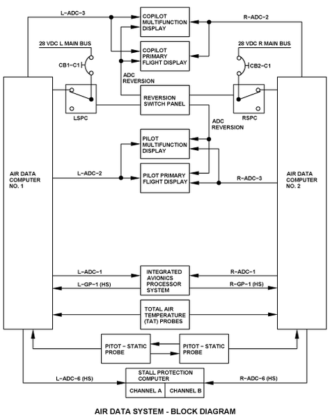
Each ADC receives air pressure and temperature data from the pitot static probes and the total air temperature (TAT) probes.
The air data computers transmit data on ARINC 429 low-speed buses as follows:
- ADC No. 1 transmits air data display parameters to the pilot PFD and MFD via the L-ADC-2 bus
- ADC No. 2 transmits air data display parameters to the pilot PFD and MFD via the R-ADC-3 bus
- ADC No. 1 transmits air data display parameters to the copilot PFD and MFD via the L-ADC-3 bus
- ADC No. 2 transmits air data display parameters to the copilot PFD and MFD via the R-ADC-2 bus
- ADC No. 1 transmits air data parameters to the IOCs in the IAPS via the L-ADC-1 bus
- ADC No. 2 transmits air data parameters to the IOCs in the IAPS via the R-ADC-1 bus
The air data computers transmit/receive data on ARINC 429 high-speed buses as follows:
- ADC No. 1 transmits air data parameters to the stall protection computer (SPC) via the L-ADC-6 bus
- ADC No. 2 transmits air data parameters to the SPC via the R-ADC-6 bus
- ADC No. 1 receives speed and correction inputs from the IOCs in the IAPS via the L-GP-1 bus
- ADC No. 2 receives speed and correction inputs from the IOCs in the IAPS via the R-GP-1 bus
Air source reversion is done with the AIR DATA switch on the reversion select panel (RSP) through two relays.
One of the relays, in the left secondary power center (LSPC), controls the 28 VDC power supply of ADC No. 1.
The other relay, in the right secondary power center (RSPC), controls the 28 VDC power supply of ADC No. 2.
The ADCs get power from the following 28 VDC electrical sources:
- ADC No. 1 gets power from the 28 VDC L MAIN bus through the circuit breaker CB1-C1, on the left circuit breaker panel (CBP1)
- ADC No. 2 gets power from the 28 VDC R MAIN bus through the circuit breaker CB2-C1, on the right circuit breaker panel (CBP2)
System Test
The ADS includes self-test functions. When the ADS finds fault conditions, it provides warnings and indications to the flight crew. For details about air data flags and other ads indications on the adaptive flight display units, see the EFIS system.
12/01/15
System Monitoring
Altitude Fail
When the altitude fail signal is set because there is no altitude signal or the altitude signal is noncomputed data (NCD), either the barometric altitude tapes, digital thousands readout, and metric altitude readout go out of view, or a boxed red alt flag replaces the barometric altitude pointer, the alt flag flashes for 5 sec, then it becomes stable and stays as a boxed red alt flag.
