


12/03/15
Overview
The standby compass system supplies magnetic heading data. The system is in constant operation and is used as an auxiliary display for magnetic heading.
The standy compass system has an interface with the panel integral lighting.
12/03/15
Standby Compass
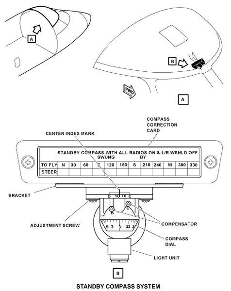
The standby compass is installed in a bracket on the center post of the windshield, above the flight guidance panel. The compass is aligned with the aircraft longitudinal axis.
The standby compass is a self-contained unit that has a transparent and molded bowl. The bowl is filled with silicon fluid containing a sphere with a compass dial. Silicone fluid ensures the sphere is free to turn, moves smoothly, and always gives an accurate indication. Metal bellows in the compass let the fluid become larger or smaller due to changes in the temperature and altitude.
A circular magnet at the top of the compass moves the sphere. The magnet is attached to a shaft in a vertical housing which turns on a jewel bearing. The standby compass has a light unit to supply light for the compass dial and the lubber line on the surface of the bowl. The light bulb is a special nonmagnetic bulb. The light unit is powered by 5 VDC from the integral lighting controller.
The compass dial shows markings for the four directional headings (N, E, S, and W) and has numerals every 30 degrees, with bars every 10 degrees. The last numeral is not shown (for example 24 means 240 degrees). Heading of the aircraft is read against the vertical lubber line. The magnetic compass operates on the principle of magnetic attraction. A magnet in the compass aligns itself with the earth’s magnetic north pole. The aircraft turns about the compass magnet and a graduated compass dial indicates aircraft heading in relation to magnetic north.
To operate correctly, the system needs installation adjustments and also corrections for the heading indications to adjust for the errors caused by magnetic interference from aircraft electrical and avionics systems. During the adjustment procedures, the heading reference is supplied by the inertial reference system (IRS). The standby compass is adjusted in the vertical axis with the two adjustment screws that attach the compass to the mounting bracket through two extended holes. At the top of the compass there is an index error adjustment scale. The center major index mark on this scale is used as a reference point during the adjustment procedures. The standby compass has also two compensators (B and C) at the top area of the compass. They adjust the readings for the magnetic interferences. During the adjustment procedures, a special key (corrector key) turns the compensators and rotates the related magnets that are located in the compass. The compass adjustment is usually done with two subsequent procedures. The primary difference between the two procedures is related to the status of the electromagnetic interference sources (engine, APU, and radio equipment).
In the first procedure, the electromagnetic sources are not energized. In this condition, the aircraft is moved to known magnetic headings to measure the compass indication errors. An index error (algebraic sum of the indication errors) is calculated and used to adjust the compass. The compass is moved clockwise or counterclockwise (as applicable), with the use of the adjustment screws. When the index error is ±2 degrees or less, compensators A and B improve the compass indication readings.
In the second configuration, all the electromagnetic interference sources are energized. In this condition, the aircraft is moved to different known headings to measure compass indication errors. The indication errors must be ±2 degrees or less. For each heading, the compass indication error is found and written on the compass correction card.

Compass Correction Card
The standby compass system includes a compass correction card installed on a bracket above the standby compass. The compass correction card has a STEER row used to write the corrected heading for each of the cardinal headings and for the 30 degrees increments.
To prevent compass indication errors, compass maintenance procedures must comply with the following conditions:
- All nonflight equipment removed from the aircraft
- Calibrator technician uses only nonmagnetic materials and tools
- Compass swing area is at the specified distances from power lines, communication cables, buildings, rail tracks, and other similar installations
- Wind speed is in the specified limit
Operation of the standby compass must be examined every 5 years or less if change or major construction occur in the area where the adjustments are done.

Operation
The compass requires no power to operate, other than that provided for illumination. Aircraft heading is read direct from a compass card relative to a vertical lubber line, engraved on the inside of the compass bowl.
Magnetic correctors are fitted within the compass body above the compass card. This enables errors, due to magnetic coefficients B and C, to be corrected. The magnetic correctors for coefficients B and C consist of small bar magnets located within the gear shafts of the corrector mechanism.
Adjustment of the correctors is achieved with the use of a special nonmagnetic corrector key inserted into either of the two apertures located in the front of the compass body. The apertures are identified by B and C engravings filled with white indicating paint.
The illumination filament lamp (nonmagnetic) is located beneath the compass card and is removed by unscrewing the lamp retaining cap and withdrawing it from the location spring.
10/19/20
Component Location Index
| Component Location Index | |||
|---|---|---|---|
| IDENT | DESCRIPTION | LOCATION | IPC REF |
| A190 | STANDBY COMPASS | ZONE(S) 211 | 34-22-01 |