


02/22/16
Overview
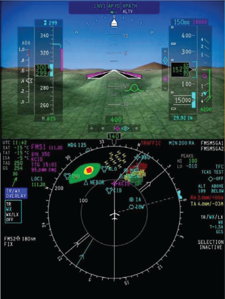
The synthetic vision system (SVS) gives virtual landscaping images for video display on the primary flight displays (PFD) with the use of a high-resolution terrain database and current aircraft position information. The SVS images give the pilot and copilot increased awareness of the surrounding terrain, airports, and runways.
The SVS uses a terrain database and current position information to generate a virtual sky-ground landscape image on the PFD background, or as a replacement when selected by the pilot, for the normal sky-ground depiction that is shown on the attitude director indicator (ADI). The SVS background is selected for display by using the REFS menu, accessible by push the REFS button on the display control panel (DCP). The SVS is used to enhance situational awareness only.
The SVS supports two types of views:
- Egocentric view: - The image of the egocentric view is from the perspective of the pilot as if looking out of the flight deck window.
- Exocentric view: - The image of the exocentric view is a from the perspective of a camera situated behind, above, and to the right of the aircraft.
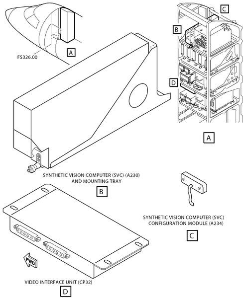
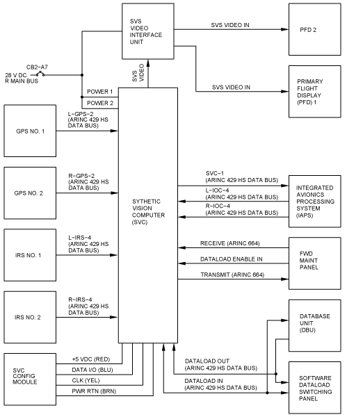
The SVS consists of an synthetic vision computer (SVC), SVS Configuration Module and Video Interface Unit and provides an egocentric view on the PFD displays. Required sensor data from all available sources are connected to the SVS which in turn will generate the SVS image. The image is brought to the displays through the composite video input. A Video Interface Unit is used to share the single SVS video output across multiple displays.
The SVS configuration module is used to provide aircraft configuration data to the SVC.
Configuration Strapping Unit (CSU) strapping is also used to indicate the SVS configuration to the SVC and to other equipment in the system.
The intended function of the Synthetic Vision System is as follows:
- Increased position awareness in all weather and flight conditions
- Increased awareness of terrain and obstacles in all flight phases and throughout the complete operational envelope approved for the aircraft
- Increased awareness of airport location and runway environment
- Visual aid while maneuvering the aircraft
- Visual enhancement to terrain alerting/avoidance system
- Visual enhancement to the primary navigation and guidance displays
The Synthetic Vision System is not intended to be used by itself for:
- Continuation of an approach, landing or take off below the minima published for that approach
- Execution of an approach, landing or take off in low visibility conditions
- As a replacement for natural or enhanced vision where there are specific visual requirements to be achieved
- As a replacement for the basic attitude, flight guidance or navigation displays and information
- The performance of any specific flight related task
- The flight crew making any judgment, decision or action that is solely based on the Synthetic Vision display
- The application of any operational credit
Overall, the SVS image dynamically changes to give the pilot increased awareness of the surrounding terrain, obstacle and cultural features. The SVS uses a terrain database and current position/altitude information to generate the SV image. The Synthetic Vision image is comprised of the following:
- Terrain (including large bodies of water)
- FMS flight plan runway at origin/destination airport
- FMS flight plan origin/destination Airport symbol
- Obstacles are not displayed on the SV image
The SVS images produced depict terrain, airport and runways. The terrain image uses data requested and received from a terrain database. The terrain data is used to show terrain close and further away from the aircraft. The range used for the resolution is dependent on altitude. Terrain is depicted as a solid object with pattern applied.
The airport and runways images uses data requested and received from an airport and runways database. The airport and runways data is used to show destination, takeoff and alternate airport runways in different color highlights. The runways are drawn consistent with usable length, width, latitude, longitude, bearing, and altitude. The runway identifier is also depicted on each runway. The runways are shown as they lie directly on the terrain surface.
The SVS is automatically removed in engine indication and crew alerting system (EICAS) reversion.
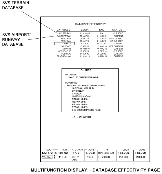
The runway/airport database is uploaded through the data base unit (DBU). The runway/airport database is required to be updated every 28 days. The terrain database update can be loaded through the service center.
The SVS uses sensor data from the following:
- Air data computer (ADC)
- Inertial reference system (IRS)
- Flight management system (FMS)
- Global positioning system (GPS) receiver
- Radio altimeter (RALT)
02/22/16
Synthetic Vision Computer
There is one synthetic vision computer (SVC) (A230) installed in the right hand side avionics rack.
The SVC renders the computer generated representation of the external environment shown on the displays. The SVC depicts airports with a simple circle icon and airport identification text. The SVC adjusts the size of the airport image based on the distance. The SVC includes the runway depictions; centerline, identifiers, threshold.
The SVC reports diagnostics to the maintenance diagnostic computer (MDC). The SVC reports database status to the AFD.

02/22/16
SVS Configuration Module
There is one synthetic vision configuration module (SVCM) (A234) installed the right hand side avionics rack . The SVCM is installed on the SVC tray. The SVS Configuration Module contains Non-Volatile Memory (NVM). Its sole function is to contain the configuration file for reading by the SVC.
The SVC unit reads the configuration module upon power-up to determine what interface options are installed, and assumes the operating characteristics appropriate to the aircraft interface. The configuration module is programmed at the time of system installation. It stores data defining the interface, mode and function options selected to match the aircraft systems and operator requirements.
02/22/16
Video Interface Unit
There is one video interface unit (VIU) (CP32) installed in the right hand side avionics rack.
The VIU is an electronic switch capable of routing video and synchronization signals to two display devices from a single display output device, or two display output devices to one display, under the control of an external discrete. Video Interface Unit can switch standard video outputs. The VIU is powered by aircraft +28 VDC, is packaged in a bulkhead mount chassis that requires no cooling.
12/19/15
System Operation
The SVS operation is completely automatic with no pilot controls needed other than the ON/OFF selection. SVS is displayed as the sky-ground background with terrain on the PFD. Synthetic Vision is selected for display on the PFD using the REFS Menu. If FPV is available and OFF, it will be automatically selected ON when SVS is ON (only for aircraft equipped with IRS). SVS is automatically removed in EICAS Reversion (Compressed ADI).
The inertial reference system (IRS) provides attitude information directly to the SVC.
The global positioning system (GPS) receiver provides the current aircraft position directly to the SVC. The position data is used to render a view matching with the current aircraft location.
The configuration strapping unit (CSU) controls the configuration of the synthetic vision system. The AFD and SVC use this information to communicate correct configuration with each other. The input/output concentrator (IOC) provides the CSU data to the AFD which then sends it to the SVC.
The IOC serves as a data concentrator between the SVC and AFDs, flight management computer (FMC) and maintenance diagnostic computer (MDC).
Synthetic Vision Computer
The synthetic vision computer (SVC) creates the computer-generated representation of the external environment shown on the pilot and copilot displays. The SVC contains the terrain database and the airport/runway database.
Terrain Database
The terrain image uses data from the terrain database with 30 arc second resolution worldwide, and down to 6 arc second resolution in an airport area. The terrain database is loaded at a service center.
Airport/Runway Database
The airport/runway database is a field-loadable database. When the current date is less than LATE EFFECTIVITY BEGIN DATE, the SVC uses the early cycle of the airport/runway database. After loading the airport/runway database on the ground, a line-of-sight to the sky must be made to update the EFFECTIVITY to show CURRENT.
Synthetic Vision Computer Configuration Module
The SVCM configures the SVC to match the avionics installed on the aircraft. Settings include type and quantity of sensors, ARINC 429 bus assignments and speed, and usage of discrete signals.
The SVCM controls the configuration to the SVC for the components that follows:
- Radio altitude receiver/transmitter
- Air data computer
- Attitude and heading reference system
- Inertial reference system
- Global positioning receivers.
Video Interface Unit
The video interface unit replicates and then sends the SVS image to the pilot and copilot PFDs.
Indication and Warning
The SVS image is removed from the PFD when any of the conditions that follow occur:
- the SVS is selected OFF
- an SVS fail is detected
- a PFD compressed format is selected
- an unusual attitude occurs
- a pitch fail occurs
- a roll fail occurs
- a heading fail occurs
- an altitude fail occurs
- an airspeed fail occurs
- a video image error is detected
- an attitude miscompare flag is shown
- a pitch miscompare flag is shown
- a roll miscompare flag is shown
- a heading miscompare flag is shown
- a PFD roll and SVS miscompare is detected
- a PFD pitch and SVS miscompare is detected
- a PFD heading and SVS miscompare is detected.
SVS Annunciators
The SVS annunciations are located on the PFD, beneath the airspeed tape.
- SVS INOP
- SVS RWY INOP
Limits
- The Sky In Fill or Ground In Fill will park or stop translating in the pitch direction overlaying a portion of the sky or ground when altitude is less than or equal to 20,000 feet and the pitch angle is greater than 13.1 degrees.
Note:
The sky or ground parks at the same location as horizon line goes out of view. - The Sky In Fill or Ground In Fill will park or stop translating in the pitch direction overlaying a portion of the sky or ground when altitude is above 20,000 feet and the pitch angle is greater than 11.1 degrees.
Note:
The sky or ground parks at the same location as the horizon line but the horizon line goes out of view at 13.1 degrees pitch up. - The AFD uses the AFD-SVS heading comparator limits of:
- the values differ by 15 degrees or more during last 1 second.
- the values differ by 5 degrees or more during the last 5 seconds.
- The AFD uses the AFD-SVS pitch comparator limits of:
- the values differ by 10 degrees or more during last 1 second.
- the values differ by 2 degrees or more during the last 5 seconds.
- The AFD uses the AFD-SVS roll comparator limits of:
- the values differ by 10 degrees or more during last 1 second.
- the values differ by 2 degrees or more during the last 5 seconds.
Controls and Displays
PFD SVS Controls
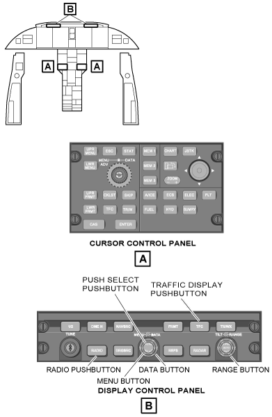
The pilot and copilot have the ability to control the SVS features with the display control panels DCP No. 1 and the DCP No. 2. The pilot and copilot DCPs provide interface controls on the pilot and copilot PFDs.
The SVS In Fill on the PFD is displayed when SVS is selected ON from the REFS 2/4 Menu. Selection of on-side SVS ON automatically selects the FPV ON (only for aircraft equipped with IRS).
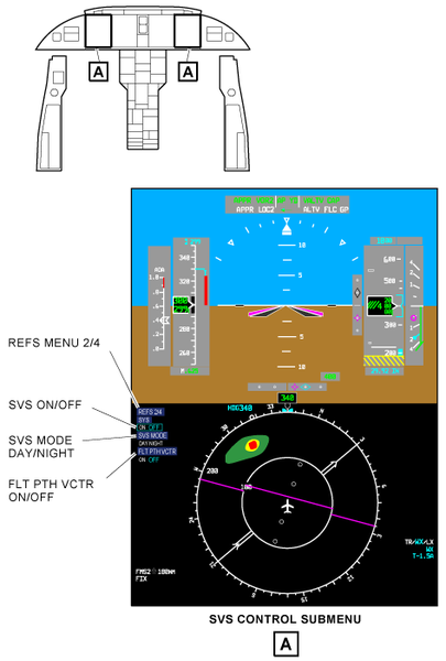
The reference (REFS) button selects the REFS menu on the PFD. Multiple pushes of the REFS button moves through the REFS menus. The REFS menu lets the pilot set and/or turn on V-speed references, approach minimums, display defaults, and SVS control. The selection of items on the REFS menu is done through use of the selection box method.
REFS Menu
The reference (REFS) button selects the REFS menu on the PFD. Multiple pushes of the REFS button moves through the REFS menus. The REFS menu lets the pilot set and/or turn on V-speed references, approach minimums, display defaults, and SVS control. The selection of items on the REFS menu is done through use of the selection box method.
REFS 2/4 Menu
The REFS 2/4 menu provides the pilot and copilot with on-side controls to select the SVS ON/OFF, select DAY/NIGHT parameters for the SVS display, and select flight path vector (FLT PATH VCTR).
MENU/DATA/PUSH SELECT (Selection Box Method)
The MENU knob is a rotary control used to move a cyan colored selection box. The MENU knob allows activation of various display items on the PFD and the MFD. The DATA knob is a rotary control used to change the value in the selection box.
The PUSH SELECT button is located in the center of the MENU/DATA knob. The PUSH SELECT button makes the value entered with the DATA knob, the active display value or change the state of the item in the selection box.
System Display
When SVS selection is ON, the area of the attitude display representing the Sky (above the Horizon Line in level flight) and Ground (below the Horizon Line in level flight) is filled with SVS image.
Display Characteristics:
- ADI dimensions are 7.98”W by 5.36”H.
- Field of View: 60 deg horizontal, 42.4 deg vertical
The SVS terrain color bands are changed based on elevation. The SVS image does not render a solid color but has texture, sunlighting and shading applied.
The solid colors are not seen as is on due to SVC processing: shading, lighting, blending, and addition of pattern. Also the AFD adds gamma, brightness and contrast corrections.
The terrain resolution is:
- 30 arc second data resolution worldwide
- 15 arc second resolution within 10 NM around airports with precision approaches
- 6 arc second resolution within 6 NM around airports with precision approaches (concentric circle within 15 arc second resolution area)


The elevation coloring is:
- Made of 11 color bands
- Color transition at every 1,000 feet from green to brown


SVS Elements
The SVS provides four elements for the PFD. These elements are listed below:
- Terrain
- Airports/ Runways
- Sky
Terrain
The SVS terrain consists of the natural surface of the earth including bodies of water without any distinct man-made physical structures. The terrain depicts the following:
- 3D terrain
- Major bodies of water
3D Terrain: The SVS image is composed of terrain drawn at different resolutions to increase system performance without giving up terrain image quality which allows the terrain in the distance to be rendered with less resolution. Therefore, large objects deep into the scene are approximately the same screen size as small objects in the foreground giving the consistent perception of detail throughout the scene.

Major Bodies of Water: Bodies of water are defined as oceans, major lakes, and major rivers. To be consistent with the water color on the navigation map and distinguishable from the sky color, terrain designated as water is defined as dark blue on the PFD.

Airports/Runways
The depiction of airport/runway information requires a flight plan in the FMS. Symbol of origin/destination airport shown when distance is between 15-10 NM. Destination airport symbol remains shown within 10 NM if no destination runway has been selected. Origin/destination runway depiction and destination runway extended centerline shown when distance is within 10 NM.
The runway markings are based out of a single common depiction which may not match the actual runway markings. The length, width and bearing is conform to ARINC 424 dimensions. The marking include an identifier, centerline and threshold. The terrain is adjusted to align with runway end points.
Sky
The sky is representative of the actual sky in the real world. Any portion of the sky which exists above the terrain horizon is a light shade of blue.


System Interface
Adaptive Flight Display (AFD)
The pilot and copilot primary flight displays (PFDs) provide display and control functions for the synthetic vision. In normal operation, the outboard AFD at each station is configured as a PFD and the inboard AFD is configured as a multi-function display (MFD). The PFD interface with the video interface unit receives an input signal. The pilot and copilot PFDs provide a day setting and a night setting.
The PFD monitors the SVS video and reports the AFD SVS video status to the maintenance diagnostic computer (MDC). The PFD enables the SVS when the CSU strapping is set. The AFD functions as a data concentrator for some data requirements to the SVC.
Cursor Control Panel (CCP)
The pilot and copilot cursor control panel provide control inputs to the maintenance diagnostic information on the MFD.
Display Control Panel (DCP)
The pilot and copilot display control panels provide the display control inputs for the on-side PFD. The pushbuttons on the DCP let the pilot and copilot select the REFS menu to get to the items to turn the SVS on and off, select the day brightness or night brightness settings and select the flight path vector.
Flight Management Computer (FMC)
The FMC provides origin, destination, and arrival airport ID, origin and arrival runway ID, and magnetic variation to the SVC. The SVC processes the inputs and uses the airport and runway ID for depiction of origin and arrival airports and runway in the SVS image.
Global Positioning System (GPS)
The global positioning units provide GPS altitude information to the SVC. The GPS unit also provides vertical dilution, GPS true track angle, GPS latitude and longitude, GPS ground speed, UTC time and date, and GPS height information inputs to the SVC.
Radio Altimeter (RALT)
The RALT provides radio altitude information to the SVC. The data is used to provide additional information in the exocentric view. The SVC support both analog and digital radio altitude types. The analog type is connected directly to the SVC, while the digital type is connected to the input/output concentrator (IOC).
Local Databases
Airport/Runway database are field loadable (ARINC 615-3) via the DBU-5010E to the SVC.
Synthetic Vision Configuration Module (SVCM)
The SVCM transmits and receives data to and from SVC over a dedicated serial communication bus. The SVCM is a serially-connected, electrically erasable programmable read only memory (EEPROM) designed to store aircraft-specific configuration data. The installer views and initializes the aircraft configuration through a specially configured laptop computer. Software interlocks restrict access to the configuration data.
Video Interface Unit (VIU)
The VIU is a video splitter capable of routing video and synchronization signals to two display devices from a single display output device or two display output devices to one display under the control of an external discrete. The VIU can switch standard video outputs.
Inertial Reference System (IRS)
The SVS computer receives IRS data (position, attitude and heading) via the L-IRS-4 and R-IRS-4 buses.
Database Unit (DBU)
The airport/runway database is updated via A429 port (615-3) of DBU-5010E.
Air Data Computer (ADC)
The ADCs provide altitude data to the SVS computer via IOC buses.
SVS Strapping
VIU Strapping
SVS Video interface Unit Pin 3 VIDEO SELECT is connected to the VIU Pin 4 VIDEO SELECT RETURN.
Configuration Strapping Unit (CSU) Strapping
CSU strapping is used to indicate the SVS configuration to the SVC and to other equipment in the system. The following is the SVS related CSU strapping:
| Word | Strap | Name | Strap Setting | Description |
| 1 | 7 | (SVS Configuration) | 0 (up) | Single configuration |
| 8 | (SVS Configuration) | 0 (up) | Single configuration | |
| 15 | 12 | Synthetic Vision | 1 (down) | SVS is Installed. |
System Monitoring
Video Signal
SVS Video is monitored by the AFD. The AFD monitors the video decoder chip for correct PAL standard signal. If the PAL signal is not within the standard as reported by the video decoder the AFD will not display the traditional sky/ground.
SVC monitors its Graphics Processing Unit to ensure image sent is:
- Fresh, Valid, at proper location, in proper color
- AFD monitors its decoder to ensure image received is within PAL standard
- AFD monitors closed caption bit pattern to ensure freshness and correct projection
AFD SVS Video status is reported to MDC.
Attitude Data
The SVS application sends pitch and roll values used to create current image via A429 data. The AFD is responsible for extracting this attitude information from the A429 data.
The on-side PFD needs to compare its attitude information with that of SVS. If there is a discrepancy then the SVS image is removed from the display. The attitude compare must be within limits to display SVS. This ensures the SVS image is not misleading.
The AFD software independently determines the computational health of the SVC LRU by monitoring the update intervals and validity of the ARINC 429 data. The AFDs software independently detects SVC LRU computation failures by comparing the reported pitch, roll, and heading attitude data values against its own source data to determine the validity of the generated image. The AFDs software does not show the terrain images received from the SVC LRU when the SVC LRU fails any one of the attitude monitor tests.
SVS will report a failure if terrain database is corrupt and then the AFD will revert to sky/ground.
- AFD controls SVC data sourcing to ensure consistency
- AFD compares its attitude with SVC output attitude to validate consistency
- If pitch/roll/HDG miscomp present between PFDs, non-flying PFD SV image removed, along with respective comparator flag(s) and CAS EFIS MISCOMP message
- If pitch/roll/HDG miscomp present between PFD and SVC, SV image removed from both PFDs and SVS annunciation is shown.
Position data
- SVC monitors GPS position accuracy
- Accuracy requirement dependant on phase of flight (en-route/terminal/approach)
- If position accuracy not adequate, SVC will report system failure and SV image is removed
System Test
Built-In Tests
- SVC performs PBIT and CBIT
- AFD monitors video input circuitry
- Results provided to the AFD and MDC
The SVC performs a Continuous Built In Test (CBIT), and an Initiated Built-In Test (IBIT). The results and maintenance status from these tests are provided to the AFD via closed caption, and to the Maintenance Diagnostic Computer (MDC) via ARINC 429.