


12/04/15
Overview
The primary function of the weather radar system is to identify areas of high precipitation along or near the flight path. Different colors are used to show the difference between precipitation rates and turbulence on the PFD and MFD displays. There is a relation between precipitation rates and turbulence intensities.
The weather radar system can also show the contour of the ground. In map mode, the weather radar changes the transmission properties and the algorithms that calculate the reflectivity levels of ground returns. In map mode, the weather radar system is set to use shorter ranges and tilt angles that point in the direction of the ground.
The multiscan weather radar system shows areas of high precipitation, that are an indication of dangerous weather. The system can also show weather turbulence areas (optional). The weather radar display shows on the pilot and copilot primary flight displays (PFD) and multi-function displays (MFD). The weather radar system monitors a horizontal area 60 degrees to the left and 60 degrees to the right of the flight path.
The system can show dangerous weather as far out as 320 nautical miles (nmi) in the flight path of the aircraft, with 100 W of transmitted power.
Weather Radar Receiver/Transmitter/Antenna
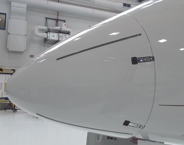
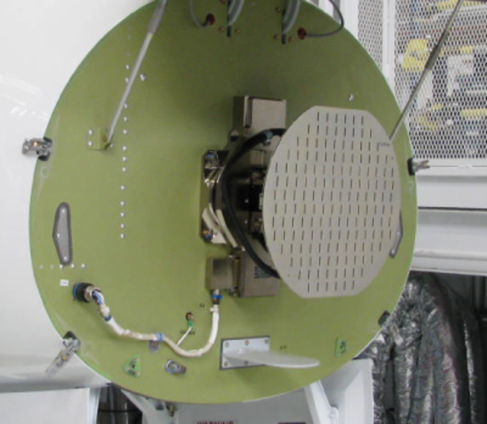
The weather radar receiver/transmitter and antenna (RTA) is a line replaceable unit (LRU) installed on the bulkhead at location FS220.00, behind the radome.
Note:
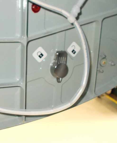
The radome can be locked from within the nose wheelwell.
The RTA is a one-piece unit that includes the components that follow:
- Radio frequency (RF) circuit
- Antenna
- Pedestal
- Base
The receiver and transmitter are connected together to make the radio frequency (RF) circuit. The RF circuit and antenna are attached to the top of the pedestal. The pedestal is attached to the base. The full unit is installed on the forward bulkhead, behind the radome.
The pedestal includes the motors, sensors, and the geartrain, that cause the antenna to move in the scan and tilt directions.
The antenna moves in a 120 degrees arc from the left scan limit to the right scan limit. The antenna can move 30 degrees (up or down) from the 0 degree position.
The pilot or copilot manually control the first 15 degrees that the antenna moves up or down. When the automatic stabilization function is on, the antenna can move 15 degrees (up or down) from the tilt angle that the pilot or copilot manually sets.
The weather radar system uses inputs from the inertial reference system (IRS) to make the radar antenna stable. The automatic antenna-stabilization function of the radar system stops the effects of the aircraft pitch and roll.
The base is the mounting base for the RTA. The base also contains the digital signal processor (DSP) card, antenna card, and power supply card.
The DSP circuits change the weather data from analog signals to the digital data that is sent to the PFD and MFD display. Other circuits on the DSP card control the input/output (I/O) functions and the high-level antenna functions. The antenna card contains the circuits that control the tilt-motor and scan-motor drive functions. The antenna card also contains the scan-to-scan memory that holds the bit-mapped images of the pilot and copilot radar displays.
The antenna is the part of the RTA that faces forward as it operates. The antenna attaches directly to the RF circuit. The antenna transmits a narrow cone-shaped beam of RF energy and then listens for a return signal. The antenna senses the return signal and sends it to the receiver. The receiver changes the return signal into two low-frequency analog signals and sends these signals to the DSP card.
The DSP circuits change the analog signals to digital data. The digital data then goes to digital filters that identify the reflectivity levels. The reflectivity levels are small pieces of video data that the processor writes into scan-to-scan memory. The data is put into scan-to-scan memory in row and column order to make a bit-mapped image of the radar picture. The processor reads the video data from scan-to-scan memory row by row. It transmits the data to the pilot and copilot PFD through an ARINC 708 high-speed data-bus.

12/04/15
Operation
The weather radar system uses the principle of radio echoes. The weather radar transceiver makes microwave energy and transmits electromagnetic pulses.
The energy moves through the air as a very-high-frequency wave (X-band). When this wave hits a target, part of the energy comes back to the weather radar antenna.
The receiver measures the time between the transmission of the radio wave and reception of its echo to find the target distance. The angular position of the target is the same as that of the antenna, when the echo is received. The quantity of the energy that comes back from a target is in proportion to the density of the target.
The X-band weather radar uses the reflective property of water to show radar images of rain, wet snow, and wet hail. Wind shear, clear air turbulence, and dry precipitation do not usually give sufficient reflection to show an image. The small water droplets in fog and some clouds also do not give sufficient reflection to show an image. Thus, the weather radar system does not usually see these types of precipitation.
The weather radar system has an avoidance range of 296 nmi. This lets the weather radar system show a Z4-reflectivity-level storm cell at 296 nmi as a minimum Z2-return-signal. For the radar to find a Z4-storm-cell at this range, the air must be dry. There must be no weather targets in front of the storm cell. The radome must have good transmissivity.
The strength of radar return signals decreases as the distance to a storm cell increases. As the aircraft moves nearer to a storm cell, the strength of the return signal increases. This signal can give an incorrect indication of the storm cell intensity. To correct for this, the sensitivity time control (STC) function automatically adjusts for the receiver gain, during reception of the return signal. This lets the storm cell show, at the same intensity, on the display, without relation to the range.
The table below shows the strength of a return signal as a reflectivity level.
The reflectivity levels in the table show as Z-levels (Z1 thru Z5 or turbulence). The table then identifies reflectivity levels with precipitation rates and colors. The display uses different colors to show the different reflectivity levels.

Modes of Operation
The weather radar can operate in the different modes that follow:
- STBY
- WX
- WX+T
- TURB (turbulence)
- MAP
- TEST
The weather radar system energizes in the standby (STBY) mode. In standby mode, the transmitter, receiver, and antenna functions do not operate.
The antenna stays at the 0 degree scan and tilt positions (in the forward direction), when the weather radar system is in standby mode. The weather radar system goes to standby mode, automatically, 60 sec after a landing.
The selection of standby mode from the pilot or copilot DCP (with the use of the RADAR CONTROL menu that shows on the PFD display) sets the weather radar system to STBY mode.
When the weather radar system is in standby mode, the selection of another mode (from the pilot or copilot DCP) puts both sides into that mode. The pilot and copilot then can make the selection of independent radar modes. When the pilot or copilot makes the STBY selection on the RADAR CONTROL menu, standby is put on both the pilot and copilot PFD.
In the WX mode, the weather radar system finds and shows only precipitation. The sequence of colors below shows the reflectivity levels of precipitation from light to heavy:
- Green
- Yellow
- Red
- Magenta
The path attenuation compensation (PAC) and sensitivity time control (STC) functions are on when the weather radar system operates in WX mode, WX+T, and TURB mode. The PAC is provided within a 80 nmi range in front of the aircraft.
The PAC function adjusts for absorption of the radar beam, when it goes through precipitation cells. The STC function keeps the proportions and the intensity of a precipitation cell at the same level, that is not in relation to the range.
In WX+T mode, the weather radar system finds and shows precipitation and turbulence. The turbulence part of WX+T mode operates only when the range selection is 50 nmi or less.
In TURB mode, the weather radar system finds and shows only turbulence. The range selection must be 50 nmi or less for the TURB mode to operate. The TURB mode automatically changes back to WX+T mode 30 sec after its selection.
In the MAP mode, the weather radar system shows a map of the ground terrain below and in front of the aircraft. The PAC and ground clutter suppression (GCS) functions are automatically set to off when the weather radar system operates in MAP mode.
The overflight protection function helps prevent thunderstorms from falling below the radar beam and off of the radar display during high altitude cruise. If a cell that is a threat to the aircraft begins to fall below the radar beam, the multiscan weather radar displays the stored digital image of the storm, to make sure that any threat thunderstorm remains on the display until the aircraft moves passed the thunderstorm. The overflight protection function becomes operational above 22,000 ft MSL and the radar bottom beam information increases to make sure approximately 6,000 ft of separation below the aircraft of threat thunderstorms while at cruise altitude. The overflight protection function does not operate in manual mode.
The variable temperature based gain function compensates for variations in geographic location, time of day, and altitude to optimize gain settings and weather returns.
The sequence of colors below shows the reflectivity levels of ground targets from smallest to largest:
- Cyan
- Green
- Yellow
- Magenta
In TEST mode, the weather radar shows a test display (a half-circle spoke pattern) on the radar display (both pilot and copilot MFDs and PFDs) as an alternative to the weather data. The antenna moves during test mode, but the transmitter does not operate.
Controls and Displays
Weather Radar Controls
The pilot and copilot DCPs control the mode, range, and other radar functions. The pilot and copilot can set different radar functions from their DCPs to show a different radar display on the pilot and copilot PFD or MFD.
The DCP controls are used in relation to the RADAR CONTROL menu. Also, some controls on the cursor control panel (CCP) are used to control the weather radar-display format on the MFD.
CCP 1/ CCP 2 Radar Controls
The dual CCP configuration has CCP 1 to control pilot MFD and CCP 2 to control copilot MFD.
The LWR FRMT pushbutton on the CCP 1 or CCP 2 is pushed to do the selection of the display format on the pilot or copilot MFD. The weather radar display shows on present position (PPOS) map format.
The TR/WX pushbutton on the CCP 1 or CCP 2 shows the terrain (TR), weather (WX), and/or (optional) lightning (LX) overlay displays on the pilot or copilot MFD.

DCP Radar Controls
The DCP TR/WX pushbutton shows the terrain or the weather radar overlay display-format on the PFD display. The display changes from one format to the other, each time the pilot/copilot pushes the TR/WX pushbutton.
The RADAR pushbutton, on the DCP, shows or removes the RADAR CONTROL menu from the PFD display each time the pilot/copilot pushes the pushbutton.
A selection box moves from item to item on the RADAR CONTROL menu when the pilot/copilot turns the MENU button (large outer button), on the DCP.
The possible selections for a menu item in the selection box change as the pilot/copilot turns the DATA button, on the DCP.
The PUSH SELECT pushbutton, on the DCP, sets an item selection to active status.
The tilt angle of the radar antenna changes when the pilot/copilot turns the TILT button (large outer button of the TILT-RANGE control). The tilt angle can be set from -15 degrees thru +15 degrees.
The display range of the weather radar system (radius around the aircraft symbol) changes when the pilot/copilot turns the DCP RANGE button (small inner button of the TILT-RANGE control).

RADAR CONTROL Menu
The pilot and/or copilot DCP use the RADAR CONTROL menu to do the selection of the MODE menu items that follow:
- STBY
- WX
- WX+T
- TURB
- MAP
- TEST
The pilot and/or copilot DCP also controls the selection of the RADAR CONTROL menu functions that follow:
- GCS (ON or OFF)
- GAIN (-3, -2, -1, NORM, +1, +2, or +3)
If the radar finds a precipitation cell with heavy rainfall, an annunciation shows on the PFD display. The path attenuation compensation (PAC) alert shows areas of unknown rainfall rates caused by intervening areas of precipitation.
Selection of ground clutter suppression (GCS) function removes the ground-return data from the radar display. The GCS function operates only when the weather radar system is in the one of the modes that follows:
- WX
- WX+T
- TURB MODE
The GAIN function changes the receiver gain in +6 dB increments. The receiver gain is at a preset level when the GAIN selection is NORM.
The possible GAIN selections are as follows:
- -3
- -2
- -1
- NORM
- +1
- +2
- +3
Weather Radar Displays
The radar display shows the radar weather data and annunciations related to the weather radar status.
Weather Data Display
Weather data shows in the compass rose area, as colored cells in relation to the reflectivity level. Distance indication to the precipitation/turbulence area is given by the range rings. The range value shows at the 10 o'clock position.
The PAC alert function shows a yellow bar on the radar display, above areas where the precipitation cells possibly do not show. The yellow bar also shows above areas where the precipitation cells do not show correctly. The rainfall rate in these areas is unknown, because receiver gain is at its maximum limit. There is no more gain to adjust for more absorption of the return signal.
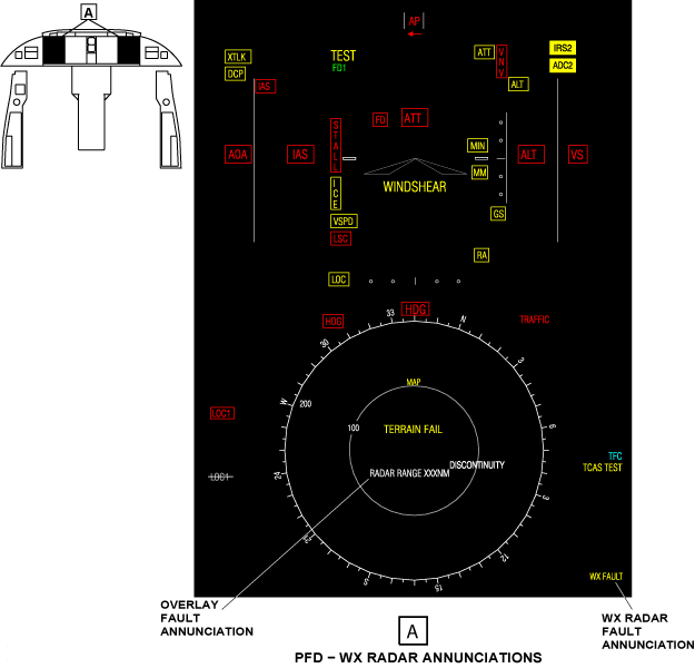
Overlay Fault Annunciation
The overlay fault display is below the map center on the PFD and MFD displays. A white RADAR ON annunciation shows if the weather radar system is not set to standby or test mode (in 65 sec or less) after the landing. The annunciation flashes for 5 sec and then stays on.
If the weather radar system is energized while the aircraft is on the ground, the white RADAR ON annunciation shows. This occurs when the weather radar system is not set to STBY (standby) or (TEST) test mode in 3 sec or less after the system energizes. The annunciation flashes for 5 sec and then stays on. The radar display does not show on the PFD or MFD, if the range data from the radar does not agree with the display range. The range data must not agree for 3 sec or more. A white RADAR RANGE XXX NM annunciation shows the range value from the radar.
The annunciation is removed when the RADAR pushbutton on the DCP is pushed.
Note:
Other annunciations can show in the overlay-fault display area when the terrain-overlay display format shows.
Radar Status Display
The overlay format annunciation (TR/WX/LX) shows in the first line of the radar status display area. The TR/WX/LX legend display identifies the PFD overlay display-formats that follow:
- TR - terrain
- WX - weather radar
- LX - lightning
If the overlay display-format selection can show with the primary display format, the TR/WX/LX legend shows in the lower right corner of the PFD. The large cyan letters in the TR/WX/LX legend identify the overlay display-format selection. The small white letters in the TR/WX/LX legend identify the overlay display formats that do not show on the display.
If the primary display format changes, the new display format can remove the TR/WX/LX legend display and overlay display format.
If the selection of a new primary display format removes only the radar display, all letters of the TR/WX/LX legend display are white.
When the radar display format shows on the MFD and PFD, the radar mode and status annunciations show on two lines below the TR/WX/LX legend. These annunciations are cyan when radar reflectivity data shows on the display. The annunciations are white if radar reflectivity data does not show on the display.
The RADAR CONTROL mode-annunciations that follow can show on the first line of the radar status display, on the PFD:
- STBY
- WX
- WX+T
- TURB
- MAP
- TEST
- GCS
If the gain selection is not set to NORM, the gain annunciations that follow can also show on the first line of the radar status display:
- G-3
- G-2
- G-1
- G+1
- G+2
- G+3
The MODE annunciation changes to a white WX OFF, if the mode data from the radar stops. The white WX OFF annunciation flashes for 5 sec and then stays on.
The annunciations for the tilt angle and the status of autotilt mode usually show on the second line of the radar status display.
The letter T and a number from -15.0 thru +15.0 show the tilt angle. If autotilt mode is on, the letter A shows after the tilt angle number.
If the sensed tilt angle does not agree with the commanded tilt angle for 3 sec or more, the tilt angle annunciation changes to yellow.
A yellow WX FAULT annunciation replaces the tilt angle and stabilization status annunciations, if there is a weather radar failure.
The yellow WX FAULT annunciation flashes for 5 sec and then stays on. The RADAR CONTROL menu can show menu selections that are not correct, when a weather radar fail-condition occurs. The WX FAULT annunciation is removed, when the weather radar system de-energizes.
Note:
When the WX FAULT annunciation shows, it is possible for incorrect data to show on the radar display that is not apparent to the pilot.
The radar status displays usually change to show the newest mode, each time the radar data is received. These displays also usually change to show the newest status annunciations, when the radar data is received. While the weather radar system operates in target mode, the gain, tilt angle, autotilt, and mode annunciations do not change.
Target/Turbulence Alert Annunciation
The target function annunciation (TGT) shows in the lower right corner of the PFD or MFD, below the third line of the radar status display. The TGT annunciation shows only on the displays of the side (pilot or copilot) that controls the mode. The radar status and mode annunciations do not change while the target function is in operation.
The TGT annunciation is cyan when the target mode selection comes from the same side as the mode annunciation shows. The annunciation changes to yellow and flashes, when the radar finds a weather target in the monitored target area. The annunciation will continue to flash until the weather target moves out of the target area. When the weather target is out of the target area, the yellow TGT annunciation changes back to cyan.
The TGT annunciation changes to white if the pilot or copilot displays do not receive data from the radar. To use target mode, it is not necessary for the radar display to show on the PFD or MFD. But the radar data must be available to the pilot and/or copilot displays.
The selection of the terrain-avoidance warning system (TAWS) causes the TAWS data to replace the weather radar data.
If the aircraft has the turbulence-weather-radar option, the radar can find the turbulence and weather targets while in target mode. A yellow TRB annunciation on the left side of the TGT annunciation flashes when the radar finds turbulence.
The SELECTION INACTIVE annunciation comes on if the pilot/copilot uses the TILT button or AUTOTILT button, when the correct annunciations do not show. This SELECTION INACTIVE annunciation comes on for 5 sec.
Display Removal Conditions
The conditions that follow will remove reflectivity data from the radar display:
- The radar range changes
- The radar mode changes, except when the mode changes WX+T to TURB modes or TURB to WX+T mode
The conditions that follow remove the radar display from the PFD and MFD:
- The selection of standby mode
- The RADAR RANGE XXX NM shows in the overlay fault display

System Interface
The weather radar system interfaces with other aircraft systems for the following functions:
- To receive the necessary inputs (control, attitude, and weight-on-wheels [WOW] condition data)
- To send its video data output for display
- To receive its power supply
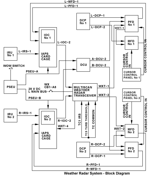
WXT Radar Inputs
Control Data
The serial control data is transmitted from the pilot and copilot DCP through ARINC 429 high-speed (HS) data buses. The weather radar control menu can be controlled by the on-side pilot or copilot DCP.
Control data from the pilot DCP is transmitted as follows:
- Data from the pilot DCP goes to the pilot PFD and MFD through L-DCP-1 and L-DCP-2
- Data from the pilot MFD goes to IOC No. 1 of the IAPS through L-MFD-1
- Data from the pilot PFD goes to IOC No. 1 of the IAPS through L-PFD-1
Control data from the copilot DCP is transmitted as follows:
- Data from the copilot DCP goes to the copilot PFD and MFD through R-DCP-1 and R-DCP-2
- Data from the copilot MFD goes to IOC No. 2 of the IAPS through R-MFD-1
- Data from the copilot PFD goes to IOC No. 2 of the IAPS through R-PFD-1.
The PFDs and MFDs also receive control signals from the CCP 1 and CCP 2, for the radar display function on the on-side displays.
Attitude Data
The pitch and roll attitude data (and also control data) from the inertial reference units (IRUs) is transmitted to the RTA through the IOCs of the IAPS on ARINC 429 high-speed data-buses as follows:
- Data from IRU No. 1 goes to IOC No. 1 through L-IRS-1
- The RTA receives the data from IOC No. 1 through L-IOC-2 ARINC 429 high-speed data bus.
- Data from IRU No. 2 goes to IOC No. 2 through R-IRS-1
- The RTA receives the data from IOC No. 2 through R-IOC-2 ARINC 429 high-speed data bus.
WOW Condition Data
The proximity sensors supply the proximity-sensor electronics unit (PSEU) with the WOW condition status. The PSEU processes the data and sends it to the IOCs and the DCU. The PSEU sends the data on ARINC 429 high-speed data-buses as follows:
- The PSEU sends the WOW data to IOC No. 1 and to the DCU through PSEU-A
- The PSEU sends the WOW data to IOC No. 2 and to the DCU through PSEU-B.
The WOW data is sent to the pilot and copilot PFD through the data concentrator unit (DCU) , on the A-DCU-2 and B-DCU-2 data buses.
WXT Radar Output
The RTA sends video data (control, annunciation, and weather data) to the pilot and copilot displays through ARINC 708 very-high-speed data bus WXT-1 and ARINC 708 very-high-speed data bus WXT-2.
The WXT-1 ARINC 708 data bus goes to the pilot PFD first. From the pilot PFD, the WXT-1 data bus goes to the pilot MFD.
The WXT-2 ARINC 708 data bus goes to the copilot PFD first. From the copilot PFD, the WXT-2 data bus goes to the copilot MFD.
The WXT-4 ARINC 429 high-speed data bus goes to the IAPS card cage (ICC).
Power Supply
The 28 V dc power from L MAIN BUS energizes the weather radar system through circuit breaker CB1-A8.
Strapping
The weather radar transceiver is strapped at the electrical connector A3P1 for the inertial reference system (IRS), turbulence threshold, and a common strap.

12/04/15
System Monitoring
The weather radar system shows yellow annunciation when one of the fail conditions that follow occur:
- If the weather radar system has a fail condition, a yellow WX FAULT annunciation replaces the tilt angle and stabilization status annunciations. The yellow WX FAULT annunciation flashes for 5 sec and then stays on.
System Test
When the TEST mode is activated, a simulated target return is used to show a rainbow like display of colors on the radar display. This verifies if the system can show weather target data. In the test mode the conditions that follow occur:
- The transmitter does not operate
- The antenna moves
- The antenna scan shows from left to right (for the pilot side) or from right to left (for the copilot side)
- A scan marker moves at the edge of the display to show the antenna position
- The range ring colors show as black, green, yellow, red, and magenta.
10/19/20
Component Location Index
| Component Location Index | |||
|---|---|---|---|
| IDENT | DESCRIPTION | LOCATION | IPC REF |
| A3 | WEATHER RADAR RECEIVER/TRANSMITTER AND ANTENNA | ZONE(S) 111 | 34-41-01 |