


Overview
The traffic alert and collision-avoidance system (TCAS) supplies the flight crew with approximate bearing, range, and altitude data of other aircraft that have transponders and that are in TCAS range. The TCAS operates with the mode S transponders to monitor an area that goes around the aircraft. The limits of the surveillance area are approximately 45 nmi in front of the aircraft, 30 nmi on each side, and 19 nmi behind the aircraft.
Interrogation signals are sent by the TCAS system to all intruder aircraft in the surveillance area that have transponders. The interrogation signal causes the transponders in the intruder aircraft to transmit the data that identifies the altitude, direction, distance, and speed of that aircraft.
The TCAS uses a traffic surveillance system (TSS) and transponder unit and a mode S transponder to coordinate with other aircraft that have a TCAS to make sure the collision-avoidance maneuvers are compatible to each other. The TCAS has a traffic identification function that gives an indication of the collision threat. This TCAS function identifies four different traffics: RA (resolution advisory), TA (traffic advisory), PROX (proximity), and OT (other traffic) traffic types.
The TCAS shows traffic type and range data, vertical-guidance commands, selection annunciations, and operation mode status on the primary flight displays (PFDs) and/or multi-function displays (MFDs). Collision threat status is shown with different symbols and colors. TCAS vertical-guidance commands are shown on the PFD vertical-speed scale.
In usual conditions, the pilot/copilot controls the TCAS operation with the MFD radio menus together with controls on the display control panel (DCP). The pilot/copilot can also use, as a secondary procedure, the display control unit (CDU) to control the TCAS. The TCAS displays are controlled through pushbuttons on the DCP and the cursor control panel (CCP).
01/06/16
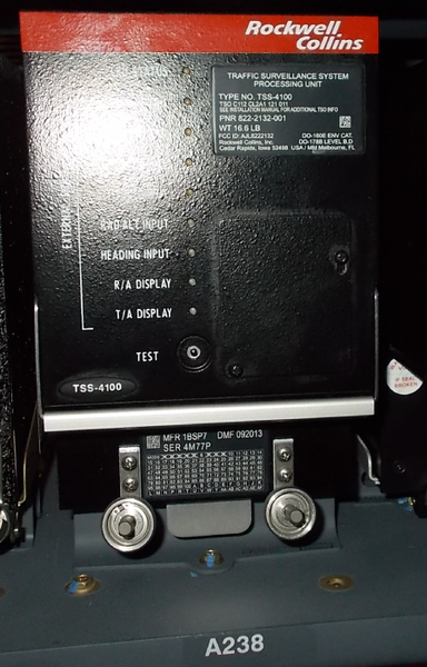
Traffic Surveillance System (TSS) and Transponder Unit
The traffic surveillance system (TSS) and transponder unit provides functionality for TCAS, Mode-S transponder and automatic dependent surveillance broadcast (ADS-B) into one LRU.
The transceiver contains the transmitter, receiver, computer, and the primary control circuits of the system. The TSS unit makes an analysis of the data from the intruder aircraft and calculates the clearance between the two flight paths.
The results of the self-test automatically supply fault data to the maintenance diagnostic computer (MDC), through the input/output concentrator (IOC) units of the integrated-avionics processor system (IAPS). The TCAS maintenance word goes first to the ATC transponder system, then to the RIUs, and then to the IOCs.
The TSS unit monitors the TSS cooling fan. The L ESS BUS supplies 28 VDC through circuit breaker CBP1-A5 to energize the TCAS/TSS system.
The TSS unit has a self-test function. The TSS unit has a TEST pushbutton and light-emitting diode (LED) test indicators on the front panel. The TCAS test can also be started from the MFD menu or from the CDU. There are nine LED indicators on the front panel of the TSS unit. The LED indicators show the results of any continuous monitoring errors detected.

01/06/16
Transponder Unit Mounting Tray
The traffic surveillance system (TSS) and transponder unit is installed in a mounting tray in the LH equipment rack. All electrical connections to the transceiver are made at the rear of the unit through an opening in the mounting tray. A cooling fan in the mounting tray supplies airflow to the transceiver.
01/06/16
TCAS Directional Antenna
The directional antenna has four elements. There is one element at each of the four 90-degrees points (0, 90, 180, and 270 degrees). Each element operates independently.
The directional antenna receives and transmits radio signals to find the direction to other aircraft. The directional antenna is installed on the top of the aircraft fuselage at FS337.00. The antenna has an hermetic aluminum seal for the protection of the elements from the weather.

01/06/16
TCAS Omnidirectional Antenna
The antenna receives and transmits radio signals to find the altitude of other aircraft. The antenna is installed on the bottom of the aircraft fuselage at FS366.04. The antenna has an hermetic seal for the protection of the elements from the weather.

Note:
Optional SB 350-34-004 replaces the omnidirectional antenna with a directional antenna.
Traffic Surveillance Antenna
The traffic surveillance antenna (TSA) is located on the top of the aircraft fuselage at FS337.00 The TSA radiates both omni-directional and directional patterns and the antenna receives and transmits radio signals to find the direction to other aircraft. The TSA is an integrated TCAS and transponder antenna. Aircraft that have the TSS unit installed, also have the TSA installed at fuselage station FS337.00.
External Compensation Unit
The external compensation unit (ECU) is used to hold all of the aircraft and unit configuration data necessary for the TSS-4100 to operate correctly. The ECU stores the TSSE file. The TSSE file is the configuration strapping file that is the same for all aircraft types. The ECU stores the Mode S address.
Operation
Functions
The TCAS system supplies the primary following functions:
- Traffic surveillance
- Collision threat detection
- Threat resolution
- Communication and coordination
The TCAS sends interrogations to other aircraft transponders, and listens for replies. The TCAS makes analysis of the reply signals to identify the possible collision threats. The TCAS transceiver transmits the interrogation signals through the omnidirectional antenna. The directional antenna receives the replies that come back from the other aircraft. The TCAS transceiver examines the data from the replies to find the direction, distance, and altitude of the intruder aircraft. With this data the TCAS transceiver calculates the possible flight path of the intruder aircraft.
The position and altitude of the intruder aircraft shows on the TCAS traffic display. If the clearance between the interrogation aircraft and the intruder aircraft is not sufficient, the TCAS identifies the collision threat. The TCAS gives voice and visual advisory messages, and commands to the flight crew to prevent possible collisions.
The TCAS transceiver causes the mode S transponder to transmit the interrogation signals at a 1 Hz rate to the other aircraft that have the transponders. The transmit frequency of the interrogation signals is 1030±0.01 MHz. The aircraft that receive the interrogation signals transmit a reply back at a frequency of 1090 MHz.
To supply these functions, the TCAS has a transceiver that includes the primary internal components that follow:
- Processor system with the related interface circuits
- 1,090 MHz receiver
- 1,030 MHz transmitter
- Video processor
- Control circuits for antenna operation (transmit/receive mode selection, antenna sensitivity control, and antenna directivity control)
- Internal power supply circuits
TCAS Traffic Identification
TCAS uses one of the following four traffic types to identify each traffic target in the surveillance area:
- Resolution advisory (RA)—Traffic that is a possible collision threat
- Traffic advisory (TA)—Traffic that can change to a possible collision threat
- Proximity traffic (PROX)—Traffic that is in a specified area but not a collision threat
- Other traffic (OT)—Traffic that is in the surveillance area but not a collision threat
Resolution Advisory
The resolution advisory (RA) gives warnings of possible collision threats. The warning includes the voice message TRAFFIC TRAFFIC and a red TRAFFIC annunciation that shows on the PFD, on the vertical speed scale. The RA gives the vertical commands (forbidden (red bar)/acceptable (green bar) vertical-speed ranges and limits) that will increase the clearance between the two aircraft. The display symbol for RA traffic is a solid red square.
Traffic Advisory
The traffic advisory (TA) tells the pilot that there is an intruder aircraft in the surveillance area that must be monitored. The TA traffic aircraft are not immediately a collision threat. But their status could change to that of a resolution advisory (RA).
The traffic advisory (TA) gives the voice message TRAFFIC TRAFFIC and shows a yellow TRAFFIC annunciation on the PFD. The display symbol for TA traffic is as solid yellow circle.
Proximity Traffic
The proximity traffic (PROX) identifies aircraft with flight routes that are between vertical limits (±1 200 ft) and horizontal limits (±6 nmi), but that are not a collision threat. The display symbol for PROX traffic is a solid cyan diamond.
Other Traffic
The other traffic (OT) identifies a traffic that is in the surveillance area, but that is not a collision threat. The OT traffic is in a range that is greater than 6 nmi, and has a relative altitude greater than 1 200 ft. The display symbol for OT traffic is an open cyan diamond.
Operation and Display Modes
The TCAS operation and display modes include:
- ATC/TCAS operation modes
- Altitude display modes
- Traffic display modes
- Other traffic altitude limits modes
- Self-test mode
ATC/TCAS Operation Modes
The possible selections for the ATC/TCAS operation modes are:
- STBY (standby)
- TA/RA (traffic advisory/resolution advisory)
- TA (traffic advisory)
- ALT ON (altitude on)
- ALT OFF (altitude off)
In STBY mode, TCAS does not show traffic on the displays or supply resolution advisories, nor does the system reply to other aircraft TCAS interrogations.
In TA/RA mode, the TCAS supplies intruder traffic display and resolution advisory (RA) vertical speed fly-to commands.
In TA mode, the TCAS supplies intruder traffic display only. It does not show resolution advisory (RA) on the PFD or MFD. It does not supply vertical speed fly-to commands on the PFD.
ALT ON and ALT OFF modes are related to the altitude report function of the ATC transponder. When the altitude mode is set to ALT ON, the ATC transponder operates in the Mode C (altitude data), but TCAS does not show traffic on the displays. Also, while the operational mode is set to ALT ON, TCAS does not supply resolution advisories, and the ATC transponder does not reply to other aircraft TCAS interrogations. The ATC transponder does reply in Mode A (identification code) and Mode C when interrogated by an ATC station.
When the altitude mode is set to ALT OFF, the ATC transponder operates in the Mode C, but TCAS does not show traffic on the displays. While the mode is set to ALT OFF, TCAS mode does not supply resolution advisories and the ATC transponder does not reply to other aircraft TCAS interrogations. Also, the ATC transponder does not reply in Mode C when interrogated by an ATC station.
Altitude Display Modes
Either absolute (ABS) or relative (REL) altitude can be selected. The REL display mode shows the altitude difference between the interrogation aircraft and the intruder aircraft. The ABS display mode shows the barometric altitude of the intruder aircraft.
Other Traffic Display Modes
The OT traffic type can be added to or removed from the TCAS display. When the OT display selection is set to ON, the TCAS shows all traffic type targets on the display. When the OT display selection is set to OFF, the TCAS does not show OT type targets.
Other Traffic Altitude Limits Modes
The TCAS surveillance area for the OT traffic is limited by the TCAS display range and altitude limits above and/or below the interrogation aircraft. The OT altitude limits are set to different values in relation to the following mode selections:
- NORM (normal mode)—2,700 ft above to 2,700 ft below the interrogation aircraft
- ABV (above mode)—9,900 ft above to 2,700 ft below the interrogation aircraft
- BLW (below mode)—2,700 ft above to 9,900 ft below the interrogation aircraft
- ABV/BLW (above/below mode)—9,900 ft above and 9,900 ft below the interrogation aircraft.
Self-Test Mode
The TCAS operates in the self-test mode to monitor the system and find fault conditions. Test results are kept in nonvolatile memory (NVM). Fault conditions are automatically sent to the MDC through the ATC transponder system, the RIUs, and the IOCs.
Controls and Displays
The TCAS operation modes and displays are usually controlled through the following radio menus:
- MFD radio menu
- ATC/TCAS CONTROL submenu
Also as a secondary procedure, TCAS operation can be controlled through two CDU radio pages:
- TUNE page
- ATC/TCAS CONTROL page
CCP/DCP Controls
The selection of the TCAS items on the MFD radio menus and the selection of the TCAS display modes on the PFD and on the MFD are done with the use of applicable controls on the control panels that follow:
- Cursor control panel (CCP) 1
- Cursor control panel (CCP) 2
- Display control panel (DCP)
These CCP and DCP controls are used for the primary functions that follow:
- For the CCP 1 / CCP 2,
- TFC pushbutton, to control the selection of the TCAS traffic display on the MFDs with current compatible display format on MFDs.
- For the DCP,
- RADIO pushbutton, to show the MFD radio menu and/or ATC/TCAS CONTROL submenu
- MENU button, to move the selection box through active menus
- DATA button, to increase/decrease numeric values or move the selection box
- PUSH SELECT pushbutton, to set a value or selection to active condition
- RANGE button, to do the selection of a TCAS display range
- TFC pushbutton, to control the selection of the TCAS traffic display on the PFD

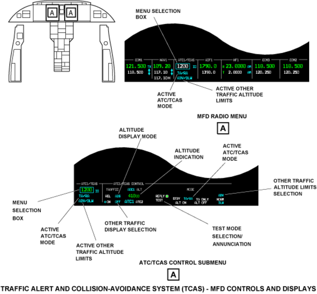
MFD Controls and Displays
MFD Radio Menu
The radio menu that shows across the bottom of the MFD is the primary radio control. If another menu is active, pushing the RADIO pushbutton on the DCP shows the radio menu. The DCP MENU button moves a menu selection box from function to function on the radio menu.
Changes to the control function must start in 20 sec or less. If the control function does not change in 20 sec or less, the menu selection box moves back to the last tuned VHF transceiver (COM1, COM2, or COM3) or HF transceiver (HF1). The MFD radio menu includes an ATC/TCAS section.
Note:
The ATC/TCAS section of the radio menu controls the TCAS system and the ATC transponder system.
The ATC/TCAS section of the MFD radio menu shows the following data:
- Active ATC/TCAS mode
- Active other traffic altitude limits
The active ATC/TCAS modes that can show in cyan on the MFD radio menu are:
- STBY (standby)
- TA/RA (traffic and resolution advisories)
- TA ONLY (traffic advisory only)
- ALT ON (altitude report function ON) and ALT OFF (altitude report function OFF)
Each turn of the DATA button moves to the next available mode selection.
The active other traffic altitude limits that can show in cyan on the MFD menu are ABV (above), NORM (normal), and BLW (below). These annunciations show the active selection from the possible selections that follow:
- NORM - 2,700 ft above and below the aircraft.
- ABV - 9,900 ft above and 2,700 ft below the aircraft.
- BLW - 2,700 ft above and 9,900 ft below the aircraft.
- ABV and BLW - 9,900 ft above and below the aircraft.
The MFD radio menu supplies other control and display functions for the ATC transponder system. The MFD radio menu also accesses the ATC/TCAS radio that contains more TCAS (and ATC transponder) display and control functions than the radio menu.
ATC/TCAS CONTROL Submenu
To show the ATC/TCAS CONTROL submenu, do the steps that follow:
- Move the menu selection box to an ATC/TCAS control function on the MFD radio menu.
- Push the RADIO pushbutton on the DCP.
The ATC/TCAS CONTROL submenu uses the DCP TUNE buttons, DATA button, and PUSH SELECT pushbutton to change the TCAS control functions.
Note:
The ATC/TCAS CONTROL submenu controls the TCAS and the ATC transponder functions.
The procedures that change the control functions on the ATC/TCAS CONTROL submenu are the same as those that the MFD radio menu uses.
The radio submenu automatically changes back to the radio menu after 20 sec if no changes are made. The radio submenu changes back to the radio menu immediately if the pilot/copilot pushes the DCP RADIO pushbutton.
The menu selection box automatically goes to the last-tuned VHF transceiver (COM1, COM2, COM3) or HF transceiver (HF1) when the radio submenu changes to the radio menu.
The ATC/TCAS CONTROL submenu includes two display areas: a narrow display area (ATC/TCAS) on the left side of the MFD display, and a wider display area (ATC/TCAS CONTROL) to the right side of the MFD display. The ATC/TCAS display area shows the same data as the MFD radio menu. The ATC/TCAS CONTROL display area shows more data for the ATC transponder and TCAS systems.
Note:
In the annunciation descriptions that follow, large cyan letters usually show active conditions or mode selections. The annunciations in small white letters usually show inactive conditions or mode selections. The annunciation colors that are not white or cyan are given in the annunciation description.
The ATC/TCAS CONTROL submenu shows the following displays:
- TRAFFIC legend with REL/ABS selection
- Other traffic symbol (open diamond) with ON/OFF selection
- ADC1 (or ADC2) ALT legend with an altitude indication
- ATC1/ATC2 selection
- REPLY legend with an adjacent box
- TEST display
- MODE displays
- ABV, NORM, and BLW selections
The TRAFFIC legend and REL/ABS selection displays show the status of the intruder traffic altitude mode:
- REL (relative) mode shows the intruder traffic altitude as relative altitude
- ABS (absolute) mode shows the intruder traffic altitude as absolute altitude.
The cyan open diamond is a symbol for other traffic (always shown adjacent to the ON legend). The adjacent ON and OFF legends show the status of other traffic. When ON selection is active (ON— large and cyan; OFF—small and white), other traffic is shown on the TCAS display. When OFF selection is active (ON—small and white; OFF—large and cyan), other traffic is not shown on the TCAS display.
ADC1 (or ADC2) ALT (and the pressure altitude indication), ATC1/ATC2, and REPLY (with its adjacent box) are displays related to the operation of the ATC transponder system.
The TEST display gives the status of the ATC/TCAS self-test function. The TEST display shows only on the ATC/TCAS CONTROL submenu. Test mode is active when the TEST display is cyan and inactive when it is white.
The MODE displays show the following ATC/TCAS operation modes:
- STBY
- TA/RA
- TA ONLY
- ALT ON
- ALT OFF
The STBY (standby) annunciation shows that the active transponder and TCAS are in standby mode at the same time. TA/RA (traffic and resolution advisories) and TA ONLY (traffic advisory only) are TCAS mode annunciations. ALT ON and ALT OFF are transponder mode annunciations.
The ABV (above), NORM (normal), and BLW (below) displays give the status of the TCAS other-traffic altitude-limits selection. The altitude limits are related to the ABV, NORM, and BLW selections as follows:
- NORM—2,700 ft above and below the aircraft
- ABV—9,900 ft above and 2,700 ft below the aircraft
- BLW—2,700 ft above and 9,900 ft below the aircraft
- ABV and BLW—9,900 ft above and below the aircraft
CDU Controls and Displays
The TUN key on the CDU keyboard, when pushed, shows the radio TUNE page on the CDU display. The TUNE page supplies display and control functions for the aircraft radio systems which include the ATC transponder system and the TCAS system. The TUNE page also gives access to the ATC/TCAS CONTROL page that has more functions for the TCAS system.
Note:
The TCAS annunciations on the CDU pages show in different colors and in different size to show status and selection conditions. Large cyan annunciations usually show active conditions or mode selections. Small white annunciations usually show inactive conditions or mode selections.
TUNE Page
On the TUNE page, the active ATC/TCAS operation mode shows in cyan, in the display line adjacent to the ATC/TCAS control line-select key. The ATC/TCAS control line-select key, when pushed, changes the ATC/TCAS mode selection to the next mode selection (STBY, TA/RA, TA, ALT ON, or ALT OFF).
Also, the ATC/TCAS control line-select key, when pushed twice, gives access to the ATC/TCAS CONTROL page.
ATC/TCAS CONTROL Page
The altitude display-mode line-select key controls if the ALT TAG shows relative (REL) altitude or absolute (ABS) altitude, on the PFD and MFD TCAS display.
When the ALT TAG is REL, the altitude difference between the intruder aircraft and the interrogation aircraft shows from -99 to +99 hundred feet. When the ALT TAG is ABS, the altitude of the intruder aircraft above sea level shows from 000 to 999 hundred feet.
The OT traffic display line-select key controls if other traffic shows on the TCAS traffic display. When the OT TRAFFIC function is OFF, the TCAS removes all OT traffic targets from the display. When the OT TRAFFIC function is ON, all types of traffic targets show on the display.
The ATC/TCAS mode line-select key sets the ATC/TCAS operation mode in the sequence that follows:
- STBY
- TA/RA
- TA
- ALT ON
- ALT OFF
The TCAS automatically goes to standby mode if the mode S transponders are off, in standby mode, or in altitude mode.
In STBY mode, the TCAS functions that follow will stop:
- The TCAS does not identify intruder aircraft in the surveillance area.
- The resolution advisories do not show on the vertical speed scale of the PFD.
- The TCAS transceiver does not reply to interrogations from other aircraft with TCAS equipment.
In the TA/RA mode, the TCAS identifies the TA and RA traffic targets. For RA traffic targets, the TCAS gives visual and voice message warnings together with vertical guidance commands. In the TA mode, the TCAS identifies only the TA traffic. The TCAS gives visual and voice message warnings when TA traffic is in the surveillance area.
The ALT ON and ALT OFF selections are for the transponder altitude-report function. The transponder altitude report mode is on in TA/RA, TA, an ALT ON. It is off when mode selection is STBY or ALT OFF.
The TEST line-select key, starts the ATC/TCAS self-test. TEST operation stops after approximately 10 sec. TEST operation does a check of the units and data that follow:
- TSS and transponder unit
- Mode S transponders
- Radio altimeter
- Heading data
- TCAS displays
The extended test line-select key sets the EXT TEST mode to ON or OFF. The aircraft must be on the ground to use the extended test mode.
When EXT TEST is set to ON, the extended test mode starts and continues operation until EXT TEST is set to OFF. The extended test mode also stops if the CDU TUN key is pushed to change the CDU display back to the TUNE page.
The three OT traffic altitude-limits line-select keys let the flight crew do the selection of the ALT (altitude) LIMITS for the surveillance area. The altitude limits are related to the NORM, ABOVE, BELOW, and ABOVE and BELOW selections as follows:
- NORM selection sets the altitude limits to 2,700 ft above and below the interrogation aircraft
- ABOVE selection sets the altitude limits to 9,900 ft above the interrogation aircraft and 2,700 ft below the interrogation aircraft
- BELOW selection sets the altitude limits to 2,700 ft above the interrogation aircraft and 9,900 ft below the interrogation aircraft
- ABOVE and BELOW selections set the altitude limits to 9,900 ft above and below the interrogation aircraft


TCAS Displays
Display Formats
The TCAS display shows the altitude and relative position of all intruder aircraft in the surveillance area that have TCAS equipment.
Note:
For the definition of the display formats, refer to the electronic flight instrument system (EFIS).
The TCAS traffic display can show as an overlay on the compass rose or present position (PPOS) display formats on the PFD. The TFC pushbutton on the DCP, when pushed, sets/removes the TCAS overlay on the PFD.
On the MFD, the TCAS traffic display can show as overlay on the PPOS display format, or it can show in a TCAS ONLY format. The TFC pushbutton on the CCP, when pushed, sets/removes the MFD TCAS overlay.
The TCAS ONLY format can show on the MFD only. The TCAS ONLY format shows the TCAS traffic without the navigation display. The TCAS ONLY format shows the TCAS display on the MFD if the TFC pushbutton on the CCP is pushed for more than one second.
TCAS Annunciations
When selection of TCAS display is set, TCAS data fields show on the display. These fields can show on the PFD and/or the MFD.
The TCAS data fields show data on seven lines of text along the lower right of the display.
The TCAS data fields show annunciations for the functions that follow:
- Traffic display status (TFC display in cyan to show that the function is on)
- Other traffic status (diamond symbol with OFF display in cyan, to show that the function is off)
- Pressure altitude (ALT legend with its altitude numerical value)
- Altitude window to show the surveillance limits (with ABOVE and BELOW displays)
- No bearing traffic data (RA/TA no bearing fields, to show data for two TA or RA intruders)
- TCAS status or mode
The TCAS status or mode annunciations show the TCAS status or the mode of operation (not applicable for the TA/RA mode). The annunciations below can show in the TCAS status or mode display field:
- TCAS FAIL (yellow)—TCAS transceiver cannot receive the sensor data or the PFD cannot receive the TCAS data
- TCAS TEST (cyan)—TCAS is in the TEST mode and the TCAS traffic display is on
- TCAS OFF (cyan)—TCAS is in the standby mode and the TCAS traffic display is on
- TA ONLY (cyan)—TCAS is in the TA ONLY mode. TA ONLY annunciation flashes yellow when TA traffic enters the surveillance area or PROX traffic status changes to that of TA traffic
- Empty display field—TA/RA is the TCAS mode of operation
When an RA or TA intruder aircraft comes into the surveillance area, a TRAFFIC annunciation shows on the PFD. It shows below and to the left side of the barometric altitude display. The TRAFFIC annunciation is red for the RA traffic and yellow for the TA traffic.
The TRAFFIC annunciation flashes for the first 5 sec and then stays on continuously. The annunciation also flashes for 5 sec if the status of a TA intruder aircraft changes to that of an RA intruder aircraft. A voice message warning is also given with the visual traffic annunciation.
The TCAS status or mode annunciations on the MFD are the same as those on the PFD, except the differences that follow:
- TCAS FAIL will not show for fail conditions that are related only to RA displays
- The MFD does not give a discrete TRAFFIC annunciation in addition to the usual display for RAs and TAs.
Vertical Guidance
The RA vertical guidance commands give the voice message commands and show visually on the vertical speed scale. The voice messages that can be given during the traffic advisories and the resolution advisories follow in the list below:
- CLEAR OF CONFLICT - the collision threat of an intruder aircraft is cancelled
- TRAFFIC, TRAFFIC - find and monitor the intruder aircraft
- MONITOR VERTICAL SPEED, MONITOR VERTICAL SPEED - monitor the intruder traffic, but do not change the vertical speed or direction. The aircraft flight path will go across the flight path of the intruder aircraft
- MONITOR VERTICAL SPEED - the collision threat of the intruder aircraft is decreased.
- CLIMB CLIMB CLIMB - increase the altitude at the rate that shows on the vertical speed scale.
- CLIMB CROSSING CLIMB, CLIMB CROSSING CLIMB - increase the altitude at the rate that shows on the vertical speed scale. The aircraft flight path will go across the flight path of the intruder aircraft
- DESCEND DESCEND DESCEND - decrease the altitude at the rate that shows on the vertical speed scale
- DESCEND CROSSING DESCEND, DESCEND CROSSING DESCEND - decrease the altitude at the rate that shows on the vertical speed scale. The aircraft flight path will go across the flight path of the intruder aircraft
- REDUCE CLIMB, REDUCE CLIMB - decrease rate of climb to the rate that shows on the vertical speed scale
- REDUCE DESCENT, REDUCE DESCENT - decrease the rate of descent to the rate that shows on the vertical speed scale
- INCREASE CLIMB, INCREASE CLIMB - follow the climb advisory that shows on the vertical speed scale
- INCREASE DESCENT, INCREASE DESCENT - follow the descend advisory that shows on the vertical speed scale
- CLIMB CLIMB NOW, CLIMB CLIMB NOW - change the vertical speed direction from descend to climb at the rate that shows on the vertical speed scale
- DESCEND DESCEND NOW, DESCEND DESCEND NOW - change the vertical speed direction from climb to descend at the rate that shows on the vertical speed scale.
The red and green bands on the vertical speed scale on the PFD show the vertical guidance commands. These commands tell the pilot how to keep sufficient clearance between the two aircraft. The green band gives direction and vertical speed range for the pilot to increase the clearance. The red band shows the direction and the vertical speed range that the pilot must not use.
Traffic Type Display
TCAS uses one of the four traffic types that follow to identify each of the traffic targets in the surveillance area:
- Resolution advisory (RA)
- Traffic advisory (TA)
- Proximate (PROX) traffic
- Other traffic (OT)
Solid-color red squares identify RA traffic on the TCAS traffic display. RA traffic is the most important of the four traffic types. An RA tells the pilot that there is a possible collision threat. The RA supplies vertical guidance and voice commands to correct the collision threat.
Solid-color yellow circles identify TA traffic on the TCAS traffic display. The TA traffic is not immediately a collision threat, but the status could change to that of an RA traffic target.
Solid-color cyan diamond symbols identify the PROX traffic on the TCAS traffic display. The PROX traffic is between ±1 200 ft vertically and ±6 nmi horizontally, but is not a collision threat.
Open cyan-color diamond symbols identify the other traffic (OT) on the TCAS traffic display. The OT traffic is in the surveillance area, but is not a collision threat.
No Bearing Traffic
The no bearing traffic is the traffic that is (or can change to) a possible collision threat but for which the TCAS system cannot calculate a bearing. For this traffic, the TCAS shows text data only of the two TA and RA intruders which have the highest collision threat.
The no bearing traffic data is shown on the PFD/MFD display in a text format on two display lines. No-bearing traffic data includes the intruder type (TA or RA), distance, and altitude. Also, an arrow gives an indication of the vertical direction of the traffic.
Altitude Display
When altitude data is available, an altitude tag shows the altitude of each intruder aircraft on the TCAS traffic display. When the altitude of the intruder aircraft is more than that of the interrogation aircraft, the altitude tag shows above the traffic symbol. When the altitude of the intruder aircraft is less than that of the interrogation aircraft, the altitude tag shows below the traffic symbol.
Relative altitude data is shown in a two-digit field that represent thousands and hundreds of feet. A "+" sign before the two-digit field shows that the intruder is above the aircraft. A "-" sign before the two-digit field shows that the intruder is below the aircraft (example:+22=2,200 ft above; -02=200 ft below).
Absolute altitude data is shown in a three-digit field (flight level) that represent ten of thousands, thousands, and hundreds of feet (example: 395 = 39 500 ft).
If the intruder aircraft altitude changes at a rate of ±500 ft/min or more, an arrow after the traffic symbol shows the altitude change direction. Relative or absolute altitude can be set for display.
Display Range
Two or three range rings can show on the TCAS traffic display. Three range rings show when the range selection is more than 5 nmi. The outer range ring (circle and marks) shows the full TCAS range selection. The middle range ring (circle and marks) shows half of the TCAS range selection. The center range ring, when applicable, is at 3 nmi. The 3 nmi range ring (marks only) shows when the full range is 5, 10, or 25 nmi. Only two range rings (the full range and half range rings (circles and marks)) show when the TCAS range selection is 5 nmi.
The PFD keeps one range value for the navigation display and a different range value for the TCAS traffic display. If there is no resolution advisory (RA) or traffic advisory (TA) traffic in the surveillance area, the TCAS traffic display uses the last TCAS range selection. If there is RA or TA traffic in the surveillance area, the TCAS traffic display is automatically set to 10 nmi.
The TCAS has a maximum range of 50 nmi. The TCAS range and navigation range change when you turn the RANGE knob on the DCP. The TCAS range changes to 10 nmi when the operator pushes and holds the TFC pushbutton on the DCP for 1 sec or more.
When the operator removes the TCAS traffic display, the navigation range will:
- Change back to the last-used navigation range if the TCAS range did not change while the TCAS traffic display was shown, or
- Stay the same as the TCAS range if the TCAS range did change while the TCAS traffic display was shown


System Interface
The TSS unit has interfaces with the other aircraft components that follow:
- Mode S transponder (TDR No. 2)
- Radio interface units (RIU No. 1 and RIU No. 2)
- Proximity-sensor electronic unit (PSEU)
- Integrated Avionics Processing System (IAPS)
- Global Positioning Receiver No. 1 and No. 2
- Primary flight displays (PFD No. 1 and PFD No. 2) and multi-function displays (MFD No. 1 and MFD No. 2)
TSS-TX-2 is a high-speed ARINC 429 data bus that supplies the collision-avoidance maneuver data to the mode S transponder No. 2.
R-TDR-XT is a high-speed ARINC 429 data bus that receives the pressure altitude data from the mode S transponder No. 2.
The TCAS control data from the CDU is also received through the L-CDU-6 data bus from the CDU No. 1.
The TCAS control data from the CDU is also received through the R-TDR-XT data bus from the mode S transponder No. 2.
L-GPS TIME MARK is a RSS—422 data bus from GPS receiver No. 1. It supplies the time/date data to the TSS.
R-GPS TIME MARK is a RSS—422 data bus from GPS receiver No. 2. It supplies the time/date data to the TSS.
TSS-TA/RA-1 is a high-speed (HS) ARINC 429 data bus. This data bus supplies the vertical resolution-advisory data to the MFD No. 1 and the PFD No. 1.
TSS-TA/RA-2 is a high-speed (HS) ARINC 429 data bus. This data bus supplies the vertical resolution-advisory data to the MFD No. 2 and the PFD No. 2.
The TSS supplies an analog audio signal (L-TSS-AUDIO-1) to the radio interface units RIU No. 1 and RIU No. 2.
This signal contains the audio voice messages that are spoken during the traffic and resolution advisories.
TCAS ADVISORY is a discrete signal to the two radio interface units that tells when a traffic advisory or a resolution advisory is on.
RA DISPLAY 1 STATUS is a discrete signal from the PFD No. 1 and MFD No. 1. If the display can show resolution advisory data, this input gets a ground through the display.
RA DISPLAY 2 STATUS is a discrete signal from the PFD No. 2 and MFD No. 2. If the display can show resolution advisory data, this input gets a ground through the display.
AIR/GND is the weight-on-wheels discrete signal from the proximity-sensor electronic unit (PSEU) that tells the TCAS/TSS when the aircraft is on the ground.
LANDING GEAR is a discrete signal from the proximity-sensor electronic unit (PSEU) that tells the TCAS/TSS when the landing gear is down and locked.
The L-TSS-1 is a low-speed (LS) ARINC 429 data bus that supplies collision-avoidance data to the IAPS and RIU No. 1.

02/02/16
System Test
The TCAS self-test function can be started from:
- The ATC/TCAS CONTROL submenu, on the MFD
- The ATC/TCAS CONTROL page, on the CDU
- The TEST pushbutton on the TCAS unit
ATC/TCAS CONTROL Submenu
The MENU button on the DCP moves the menu selection box to the TEST indication on the MFD ATC/TCAS CONTROL submenu. The PUSH SELECT pushbutton on the DCP starts the ATC/TCAS self-test operation. When the self-test functions is on, the dimension of the TEST display increases and becomes cyan. If the TEST is satisfactory, a TEST pattern shows on the PFD and/or MFD. If the TCAS test is not satisfactory, applicable error-messages show on the PFD and/or MFD.
ATC/TCAS CONTROL Page
The TEST line-select key on the ATC/TCAS CONTROL page, when pushed, starts the ATC/TCAS self-test operation. When the self-test operation is on, the dimension of the TEST display increases and becomes cyan.
Also, if the extended test line-select key on the ATC/TCAS CONTROL page is pushed, while the aircraft is on the ground, the ATC/TCAS extended-test operation starts. When the extended test becomes active, the OFF display on the CDU page increases and becomes cyan. If the ATC/TCAS test is not satisfactory, applicable error-messages show on the CDU scratchpad.
TCAS TEST Pushbutton
The TSS unit has 9 LEDs (one green and the others red) used to show operation status for the TCAS and interface systems during a test operation. The LEDs are located from top to bottom with the legends that follow:
- PASS for the TSS unit
- FAIL for the TSS unit
- XPNDR for the transponder
- UPPER ANT (upper antenna) for the directional antenna
- LOWER ANT (lower antenna) for the omnidirectional antenna
- RAD ALT for the radio altimeter
- HDNG for the heading input
- R/A for the resolution advisory function
- T/A for the traffic advisory function
At all times other than at power-up or during the self-test, the LEDs must not be on. When the TEST pushbutton (located below the bottom LED), is pushed, the TCAS test operation starts and the conditions that follow occur:
- If the test is satisfactory, all the LEDs (green and red) come on then, after test is completed, only the green is on
- If the test is not satisfactory, the applicable red LEDs come on to show the components that have fail conditions
When the TCAS test results are satisfactory, a TEST SYSTEM TEST OK aural message is heard from the loudspeakers. Also, access to the self-test results is possible through the maintenance diagnostic computer (MDC).
10/20/20
Component Location Index
| Component Location Index | |||
|---|---|---|---|
| IDENT | DESCRIPTION | LOCATION | IPC REF |
| A238 | TRAFFIC ALERT AND COLLISION-AVOIDANCE SYSTEM (TCAS) AND TRAFFIC SURVEILLANCE SYSTEM (TSS) UNIT |
ZONE(S) 221 | 34-43-03 |
| A238 | TRAFFIC ALERT AND COLLISION-AVOIDANCE SYSTEM (TCAS) AND TRAFFIC SURVEILLANCE SYSTEM (TSS) UNIT MOUNTING TRAY |
ZONE(S) 221 | 34-43-07 |
| E10 | TRAFFIC ALERT AND COLLISION-AVOIDANCE SYSTEM (TCAS) DIRECTIONAL ANTENNA |
FS337.00,BL0.00 ZONE(S) 221 |
34-43-09 |
| A235 | TRAFFIC SURVEILLANCE SYSTEM (TSS) EXTERNAL COMPENSATION UNIT (ECU) | ZONE(S) 221 | 34-43-11 |
| E11 | TRAFFIC ALERT AND COLLISION-AVOIDANCE SYSTEM (TCAS) OMNIDIRECTIONAL ANTENNA |
FS365.35,BL0.00 ZONE(S) 141 |
34-43-13 |