


Overview
The radio altimeter system gives the flight crew accurate data about the aircraft height above ground level (AGL). The radio altitude shows on the electronic flight-instrument system (EFIS) displays.
The radio altimeter is a transceiver that uses frequency modulated continuous wave (FMCW) signals to measure altitude by comparing the transmitted signal with the signal reflected from the ground. The radio altimeter system uses two antennas, one to transmit the signal and one to receive the returned signal. The transceiver processes the signals and outputs digital AGL data to the PFDs, MFDs, TAWS, and TCAS.
12/07/15
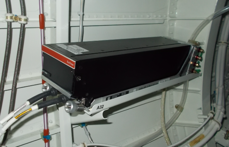
Radio Altimeter Transceiver
The radio altimeter transceiver transmits, receives, and makes an analysis of the FMCW signals. The transceiver gives aircraft height AGL in aeronautical radio incorporated (ARINC) 429 format.
The transceiver is in a mounting tray in the aft equipment compartment, at FS760.00 on the right side.
At the front, the transceiver has two hold-down hooks to attach the transceiver to the mounting tray. At the rear, the transceiver has a connector that connects to the mounting tray receptacle to interface with other aircraft systems. The radio altimeter transceiver has a swivel handle to easily remove the transceiver from the mounting tray.
The transceiver operates in a frequency range of 4,250 to 4,350 MHz. The transmitter gives the output signal to the transmit antenna and sends a sample to the receiver. The FMCW transmitter signal has a rate-of-change of 20 Hz/nsec. Because the radio frequency wave speed is 1 nsec/ft, the radio frequency wave moves 1 radar foot in 2 nsec. The transmitter signal frequency changes by 40 Hz in 2 nsec.
The receiver compares the sample transmitter signal frequency to the return signal frequency. The ratio of the frequency difference to the height AGL is 40 Hz/ft of altitude. The transceiver changes the frequency difference into digital altitude data and transmits the data to the IAPS.
The radio altimeter transceiver receives 28 VDC power from the L MAIN BUS through the left circuit breaker panel.
![]()
Radio Altimeter Transceiver Tray
The radio altimeter transceiver tray holds the radio altimeter transceiver. Two hold-down clamps on the tray engage the hold-down hooks on the transceiver. The tray is attached to the aircraft structure with four screws. The connector at the rear of the tray supplies the interface from the transceiver to the aircraft system wiring.
12/07/15
Radio Altimeter Antenna
The radio altimeter system has a transmit antenna and a receive antenna. The antennas are on the bottom of the fuselage, with the transmit antenna at FS711.00 LH and the receive antenna at FS711.00 RH.
The transmitter and receiver coaxial cables connect to the front panel of the transceiver. The transmitter part of the transceiver gives the FMCW signal to the transmit antenna, which sends the FMCW signal to the ground. The receive antenna receives the return FMCW signal and gives it to the receiver part of the transceiver.

11/13/24
Radio Altimeter Cavity-Bandpass-Filter
On A/C 20993 and Subs and On A/C 20501 to 20992 Post SB 350-34-029:
The radio altimeter bandpass-filter is installed between the receiver antenna and the ALT-4000 radio altimeter receiver unit. The bandpass filter prevents the harmful C-band frequency transmitted from the 5G mobile technology base stations from interference with the operation of the radio altimeters.

Operation
The radio altimeter transmits a reference signal with one antenna and receives the return signal with a different antenna. The radio altimeter compares the frequencies of the transmitted and received radio frequency (RF) signals. The transmitted signal is modulated with a triangular waveform, which makes the frequency difference proportional to the altitude. Aircraft installation delay inputs adjust for antenna location and cable lengths. The primary flight displays can show a maximum radio altitude of 2,500 ft. AGL.
12/07/15
Controls and Displays
Controls
The controls related to the radio altimeter data in a reference (REFS) menu on the PFD and controls on the display control panel (DCP).
REFS 3/4 Menu
The pilot/copilot pushes the REFS pushbutton on the display control panel (DCP) to show the REFS 3/4 menu on the bottom left side of the PFD display.
The REFS 3/4 menu is automatically removed from the PFD after 5 sec if no changes are made. REFS 3/4 menu is also removed from the PFD with the selection of another menu.
The last set radio altitude minimum, barometric altitude minimum, and minimum alert reference selections are kept in nonvolatile memory when the PFD de-energizes.
The following functions are set from the REFS 3/4 menu:
- BARO MIN (barometric minimum)
- RA MIN (radio altitude minimum)
- RA MIN ALERT (minimum alert)
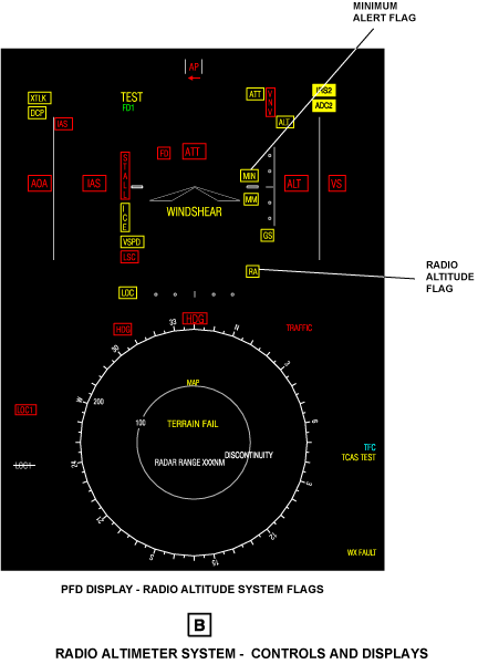
The REFS 3/4 menu shows the RA MIN and MIN ALERT indications in the bottom left of the PFD. The RA MIN indication shows the radio altitude minimum alert value. The MIN ALERT indication shows the BARO MIN, RA MIN, or OFF indications.
Minimum Selection
To change the altitude minimum value, the pilot/copilot turns the MENU button on the DCP to move the selection box to the function that is to be changed (RA MIN or BARO MIN). Then, the pilot/copilot uses the DATA button on the DCP to change the altitude value of the barometric or radio altitude minimum.
Minimum-Alert Selection
To set the MIN ALERT selection to BARO, RA, or OFF, the pilot/copilot turns the MENU button on the DCP to move the selection box to the MIN ALERT selection.
Then the pilot/copilot uses the DATA button or the PUSH SELECT pushbutton on the DCP to change the MIN ALERT selection to BARO, RA, or OFF. The selection that is on shows in larger cyan letters. The other selections are shown in smaller white letters.
Displays
The radio altitude display shows the aircraft altitude above the ground in the range of 0 to 2,500 ft. The radio altitude display comes into view when the radio altitude is ≤2,500 ft.
The radio altitude display shows on the pilot and copilot PFDs. The radio altitude display includes the following displays:
- Digital radio altitude display
- Analog radio altitude display
- Radio altitude minimum display
- Radio altitude minimum alert flag
- Radio altitude flag
Digital Radio Altitude Display
The digital radio altitude display shows in the 6 o’clock position on the attitude ball display. If the radio altitude is more than the radio altitude minimum (RA MIN), the radio altitude display shows in green digits on black.
If the radio altitude is less than or equal to the radio altitude minimum (RA MIN), the radio altitude display is yellow and flashes for 5 sec. After 5 sec the radio altitude display is yellow and stable.
The digital radio altitude display shows the radio altitude in the increments and ranges that follow:
- Shows 0 for negative input values
- Shows 5 ft. increments from 0 to 199 ft.
- Shows 10 ft. increments from 200 to 999 ft.
- Shows 50 ft. increments from 1,000 to 2,500 ft.
- Removes the display for input values >2,500 ft.
Analog Radio Altitude Display
The analog radio altitude display shows on the PFD for a better ground awareness. It shows at the bottom of the barometric altitude display as a brown ground bar that comes into view when the aircraft is between 0 and 270 ft above ground level.
The brown ground bar moves up to the 0 ft mark when the radio altitude decreases.
Minimum Display
The minimum display shows altitude minimums: decision height (DH) or minimum descent altitude (MDA). The minimum display shows on the PFD in digital format and in analog format.
The digital minimum display shows below the barometric altitude display. The format is MIN XXXX RA if the MIN ALERT is set to RA. The format is MIN XXXX BARO if the MIN ALERT is set to BARO. The letters XXXX give the altitude that is set. RA or BARO show that it is a radio altitude minimum or barometric altitude minimum. The analog radio minimum display shows as a cyan bar at the bottom area of the barometric altitude display.
One or the other of the conditions that follow cause the minimum altitude selection data to show automatically on the display:
- Radio altitude minimum alert function is set to on and the radio altitude minimum is set to ≤2,500 ft
- Barometric altitude minimum alert function is set to on and the barometric altitude is ≤2,500 ft above the barometric altitude minimum that is set
Minimum Alert Flag
When MIN ALERT selection (on REFS 3/4 menu) is set to RA, and the altitude is less than or equal to the radio altitude minimum (RA MIN). The letters MIN in a box show at the 3 o'clock position on the attitude ball display. This MIN flag is yellow and flashes for 5 sec. After 5 sec, MIN becomes a stable yellow indication.
Radio Altitude Flag
The radio altitude (RA) red flag shows on the PFD to let the flight crew know that the radio altimeter is in a fail condition.


System Interface
The radio altimeter system sends data to the electronic flight instrument system (EFIS) and to the terrain avoidance and warning system (TAWS), through the input/output concentrator (IOC) units.
The radio altimeter transceiver gives the altitude data, on two ARINC 429 low-speed buses, as follows:
- The radio altimeter sends the data to the IOC No. 1 on the L-RALT-1 data bus. (The Traffic Surveillance System (TSS) interfaces with the IOC to retrieve radio altitude data)
- The radio altimeter sends the data to the IOCs No. 2 on the L-RALT-2 data bus.
The input/output concentrators No. 1 and No. 2 give the radio altitude data to the following displays:
- Pilot and copilot primary flight display (PFD)
- Pilot and copilot multifunction display (MFD)
Also, the input/output concentrator No. 1 gives the radio altitude data to the TAWS system. The L MAIN BUS supplies 28 VDC power to the radio altimeter transceiver through circuit breaker CB1-A7 on the left circuit breaker panel.

System Monitoring
If a fail condition of the radio altimeter occurs, the green digital and brown analog radio altitude displays are removed. Also, the PFD shows the letters RA (in a red box) on the attitude ball display, to the left of where the digital altitude display was shown.
An additional antenna monitoring feature is enabled (P1-21 strap) that tests the antenna cable connections for errors.
10/19/20
Component Location Index
| Component Location Index | |||
|---|---|---|---|
| IDENT | DESCRIPTION | LOCATION | IPC REF |
| A32 | RADIO ALTIMETER TRANSCEIVER | FS756.25, WL97.27, RBL29.66 ZONE(S) 312 |
34-44-01 |
| - | RADIO ALTIMETER TRANSCEIVER TRAY | FS756.25, WL97.27, RBL29.66 ZONE(S) 312 |
34-44-05 |
| E8 | RADIO ALTIMETER TRANSMIT ANTENNA | FS711.50, WL58.00, LBL11.50 ZONE(S) 182 |
34-44-09 |
| E9 | RADIO ALTIMETER RECEIVE ANTENNA | FS711.50, WL58.00, RBL11.50 ZONE(S) 182 |
34-44-09 |