


03/30/22
Overview
The Inertial Reference System (IRS) comprises dual Honeywell Laseref VI (LRVI) IRUs. It provides the required parameters to the flight displays and other avionics system such as Attitude (Pitch and Roll), Magnetic and True Heading, Angular rates and Angular accelerations, Inertial Altitude and Vertical Speed, Linear rates and Linear accelerations, Track angle and Ground speed, Wind speed and wind direction, Flight Path Angle, Aircraft Position, IRU status and IRU maintenance information.
The IRS supplies the attitude and magnetic or true heading to the AFCS, EFIS, FMS, navigation systems, and the WXR. The system is made up of two Inertial Navigation Units (INU). The INU generates and supplies the attitude and heading data to the EFIS and other subsystems by way of the IAPS and the system bus structure. Attitude and heading data from the cross-side can be selected to drive on-side systems in the event of an on-side INU failure.
The Inertial Reference Units are physically and functionally isolated from each other and each one providing four output busses of ARINC 429 High Speed (HS) busses.

12/08/15
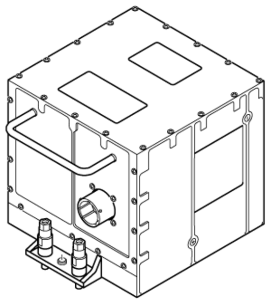
Inertial Reference Unit
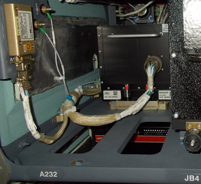
There are two inertial reference units (IRUs) installed in mounting trays, in the equipment racks. The IRU No. 1 is installed in the LH equipment rack. The IRU No. 2 is installed in the RH equipment rack. On the front panel, the IRU has an electrical connector for the interface with the other IRS components and aircraft systems. The IRU has two captive screws used to attach the unit to its mounting tray. The two IRUs are installed at FS326.25
Each IRU operates from either a primary input +28 VDC aircraft power source or a secondary input power source. The secondary power input source includes either +28 VDC aircraft power or +24 VDC battery. The IRU operates normally and only from the primary input source when the primary input voltage is between +18 VDC and +36 VDC. If the primary DC input voltage is less than +18 VDC the IRU switches to secondary power source without interruption to normal operation if the secondary input voltage is between +18 VDC and +36 VDC.
The IRU has Inertial Reference (IR) and Global Positioning (GP) sections.
IR Section
The inertial reference section contains three force-rebalance accelerometers and three laser gyros which the IRU uses to measure inertial motion. The IR section receives system initialization data from systems such as flight management system or GPS receiver. The IR section also receives air data system (ADS) altitude, altitude rate, and the true airspeed inputs on ARINC 429 input buses. From these measurements and inputs, the IRU continuously calculates and outputs body frame, local level frame, and earth frame parameters.
GP Section
The global positioning section uses existing IR hardware components to receive GPS data from GPS receivers. The GP section receives on time mark signal unique for each GPS receiver and GPS satellite measurement data. The GPS hybrid function blends the receiver GPS autonomous pseudo range with inertial and air data altitude to achieve optimal position, velocity, and attitude performance.
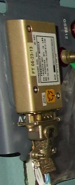
Aircraft Personality Module (APM)
The Aircraft Personality Module (APM) is a self-contained, non-volatile memory (NVM) device that is mounted externally from the IRU. It stores program pin discrete data, mount misalignment Euler angles, aircraft type and serial number, and configuration-specific option selections.
The IRU provides the 5 VDC power to the APM. The power is provided with current limit protection to prevent a pull down of the internal IRU 5 VDC supply. The APM requires power during the IRU power up, at which time memory module tests are performed, and during regular IRU operation.
Each APM interfaces only with one IRU, which is its sole provider of power. It is wired directly to that IRU (RS-232 interface) and provides no other interface to another device in the aircraft.
The IRU uses APM data for computing mount misalignment and aircraft-specific data.

12/08/15
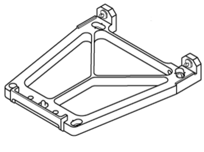
Mounting Tray
The inertial reference unit (IRU) tray is a low-profile, lightweight non-standard tray that consists of machined aluminum and stainless steel bushings and fittings. The IRU mounting trays hold the IRUs in the equipment racks. The LH IRU tray holds the IRU No. 1. The RH IRU tray holds the IRU No. 2. Two rear guide pins and a front guide pin on the tray engage bushings on the IRU and attach it to the tray. Two captive screws on the IRU secure it to the tray. A precise alignment of the tray surface is necessary for the inertial reference unit to give accurate attitude data.
The IRU mounting tray does not have electrical connectors. The electrical connector on the front panel of the IRU gives the interface from the unit to the aircraft system wiring.
12/08/15
Operation
The IRU has to be aligned to the three axis before it can operate correctly on the aircraft. It does not require shims to fine-tune its tray alignment to the aircraft. Instead it calibrates itself to the tray on the location it is installed and stores the misalignment errors on the Aircraft Personality Module (APM), which retains the information in read-only memory to be retrieved by a new IRU, should the original IRU needs to be replaced. The APM data stays valid as long as the original tray installation is untouched. If the original tray has to be removed or even if its screws are loosened for any reason, it has to be realigned to the three aircraft axis. The use of the APM replacing the shims require that before the alignment is initiated, the IRU tray installation is complete and that it is mounted within 5 degrees of the aircraft roll, pitch, azimuth axis; otherwise IRU halts the alignment process.
The IRU has the following modes of operation:
Power-up Mode
The IRU enters the power-up mode when its power is cycled from OFF to ON. The IRU performs secondary power input testing during the power-up mode and normal operation. During the power-up mode, it tests its ability to switch from its primary to its secondary power source and it also tests the secondary power source voltage level. The IRU is capable of a warm start, which means that it can quickly recover valid attitudes after both the primary and the secondary powers have been interrupted for up to 350 ms after the IRU has shutdown and is no longer operating. It does a test during the power-up mode to determine the duration of power loss.
During normal operation, the IRU tests the secondary power input source at a minimum of once every 1.5 seconds to ensure that the voltage does not fall below 18.0 ±0.4 VDC. When the IRU completes the power-up mode, it concurrently enters the Erect Attitude Mode.
Alignment Mode
IRU aligns its reference axes to the local vertical and make sure of the latitude by the calculation of the horizontal earth rate components. The LRVI uses GPS data for any of its alignment modes and to compute its GPS/IRS hybrid outputs.
When the IRU enters the power-up mode, it selects a warm-start or a normal operation power-up after it detects how long it has not had power.
When the IRU completes the power-up mode, it concurrently enters the Stationary Alignment mode and either the Erect Attitude submode or Reversionary Attitude mode. After a normal operation power-up, the IRU enters the Erect Attitude submode, but after a warm-start power-up, the IRU bypasses the Erect Attitude submode and transitions to the Reversionary Attitude mode. From the start of the Reversionary Attitude mode, the IRU continuously tests for the Alignment In Motion (AIM) entry conditions. Following successful completion of a Stationary Alignment mode, the IRU exits both the Stationary Alignment mode and the Reversionary Attitude mode and transitions to the Navigation (NAV) mode.
If the IRU detects sufficient motion, it enters the Align In Motion (AIM) mode. The IRU continues to process the Reversionary Attitude mode following transition to the AIM mode, and when the required performance level is achieved, it switches from the Reversionary Attitude mode to the AIM attitude mode while continuing to process the AIM mode. Following successful completion of the AIM mode, the IRU exits both the AIM mode and the AIM Attitude mode and transitions to the NAV mode.

The IRU has the three alignment modes that follow:
Stationary Alignment Mode
The Stationary Alignment process is performed to align IRU reference axes to the local level frame with high accuracy and estimates the horizontal earth rate components to compute latitude. Then, it calculates correct north from the ratio of the horizontal earth rate components. Stationary alignment time changes as a function of latitude. Since it uses the earth rate which decreases with latitude.
The LRVI performs an alignment via the Stationary Alignment mode if at least one of the following conditions is true:
- The IRU has completed the Erect Attitude submode (performed immediately following a Normal Operation Power-up mode) or Warm Start Power-up mode.
- The previous IRU power cycle ended during an on-ground condition and Stationary Alignment excessive motion with ground speed in excess of 30 knots does not occur before the IRU enters Navigation mode.
Note:
If both the GPSs are valid, it will receive data from both of them simultaneously, but only data from the onside GPS will be used for its initialization.
Alignment In Motion Mode
The Alignment In Motion (AIM) mode is a process to get full inertial navigation functions. In this mode, the IRU calculates the body to the local level frame and the local level frame to earth coordinate transformation matrices necessary to give full inertial reference navigation function.
The IRU performs an alignment via the Align In Motion (AIM) mode if all of the following conditions are met:
- The IRU has completed the Erect Attitude submode (performed immediately following a Normal Operation Power-up mode) or Warm Start Power-up mode.
- GPS data is valid.
- A GPS Ground Speed value greater than 30.0 knots is received, and at least one of the following conditions exists before the IRU enters Navigation mode:
- The previous IRU power cycle ended with an in-air condition (indicating that the IRU is likely being powered up in the air).
- Excessive motion is detected by the IRU.
Once the IRU enters the Align In Motion mode it remains in that mode until the alignment is complete and IRU power cycle is complete. Loss of valid GPS data during Align In Motion causes the Align In Motion time to be reset to the maximum indicated Time to Nav count and counting down will resume once valid GPS data is again received. The time period to complete the align in motion alignment is usually between 10 to 20 minutes. The Time to Nav count value provides a good indication of how effective the current flight trajectory is in allowing the IRU to complete an alignment in motion. If the Time to Nav count is not progressing towards zero, then changes to the aircraft's heading and acceleration may be necessary for the IRU to complete an alignment in a timely manner.
The Align In Motion processing time will vary as a function of latitude, changes in aircraft heading, and changes in aircraft acceleration. Typically, the time period to complete Align In Motion is between 10 and 20 minutes. However, the Align In Motion alignment time may exceed 20 minutes if any of the following flight dynamic conditions are present either alone or in combination:
- No changes in heading during alignment.
- No changes in acceleration during alignment.
- An East to West flight trajectory such that the IRU’s sensed rotational rates in inertial space are nearly equal to zero.
Align In Motion mode will ride through temporary loss of satellite measurement blocks to the extent the Horizontal Integrity Limit (HIL) does not exceed 2.0 nautical miles. In Align In Motion mode, the transition to Nav mode is not limited to an upper/lower latitude limit as it is in Stationary Alignment. Full alignment of the IRU can be performed worldwide (provided the GPS data conditions are met), regardless the latitude, because in that case the IRU completes its alignment based on GPS data, instead of using Earth rate, which is the method used in the stationary alignment.
Note:
The Time To Nav count value provides a good indication of how effective the current flight trajectory is in allowing the IRU to complete an alignment in motion. If the Time To Nav count is not progressing towards zero, then changes to the aircraft’s heading and acceleration may be necessary for the IRU to complete an alignment in a timely manner.
The IRU requires valid GPS input on one of the GPS input ports throughout the Align In Motion period to complete the alignment. Provided GPS data is valid, based upon the reception of a valid Horizontal Integrity Limit, position, and ground speed, no further integrity checks are performed on the received position (i.e. a position comparison test is not performed in this mode). GPS data is accepted as a set from a single GPS input bus source. Invalid GPS data from one source causing a GPS channel switch will result in the Align In Motion mode being restarted.
The IRU max time to Nav range (sent to the FMS) is 9.9 min. When initially in AIM, the time to Nav will exceed 9.9 min (it may be as high as 20 min), while the FMS CDU indication in the POS INIT 3/3 page will be 9 until the time to Nav goes below 9.9 min.
Auto Realign Mode
Auto realignment (AR) is a process that causes the velocities to be trimmed to zero, and the attitude and heading errors to be corrected.
The three conditions under which Auto Realign mode is activated are:
- Extended Alignment Auto Realign: The first AR activation condition is referred to as extended alignment AR, where alignment is extended following a stationary alignment to navigation mode transition and motion is not detected. The IRU applies the first AR estimate at 1.0 ±0.1 minute following the extended alignment AR mode transition and at 1.0 ±0.1 minute intervals until it detects excessive motion. During the extended alignment AR period, the IRU accepts position updates from any general purpose input bus. The IRU will not accept automatic position update from the GPS input bus during this period to prevent the pilot entered position from being overwritten. Time in nav will not start counting until the IRU experiences motion causing it to exit extended alignment AR.
- Pre-Flight Auto Realign: The second AR activation condition is referred to as pre-flight AR, where AR updates are performed when the aircraft becomes stationary for a period of time after the end of extended alignment AR condition because of the movement. If extended alignment AR ends prior to the first flight, IRU enters pre-flight AR if motion is not detected over the AR no motion time period. In pre-flight AR condition, the IRU immediately applies the AR estimates at 1.0 ± 0.1 minute intervals until motion is detected. During the pre-flight AR period, the IRU accepts position updates from a general purpose bus. The IRU will not accept the automatic position update from the GPS input bus during this period to prevent the pilot entered position from being overwritten. When the inertial ground speed is more than 80 kts, further entries into pre flight AR are stopped until a stationary alignment is done again.
- Post-Flight Auto Realign: The third AR activation condition is referred to as post-flight AR, where AR updates are performed when no motion is detected over the AR no motion time period following a flight and inertial ground speed is less than 30 knots. In post-flight AR condition, the IRU applies the AR estimates at 1.0 ±0.1 minute intervals until motion is detected. After the initial post-flight AR is followed by motion, the IRU may enter post-flight AR any number of times prior to the next flight.
A motionless condition is determined by monitoring the magnitude of heading and velocity changes over a 10 second interval to remain under following limits:
- Heading less than 0.2 degrees or
- Change in velocity of less than 0.46 ft/s
Thus, the aircraft must remain relatively motionless for the entire AR motionless period before pre-flight or Post-Flight Auto Realign corrections are applied. A post-flight residual ground speed that exceeds 30 knots may be due to a sensor anomaly within the IRU. A Post-Flight Auto Realign will not be executed if the inertial residual ground speed exceeds 30 knots so as not to mask an anomalous IRU.

Attitude Mode
The attitude mode rapidly makes sure of the correct pitch and roll attitudes, body acceleration rates and linear accelerations after the completion of the power-up mode.
Reversionary Attitude Mode
In the reversionary attitude mode, the IRUs supply pitch and roll attitudes, body rates and accelerations and changes in the platform heading relative to a magnetic heading input entry. Following completion of a normal operation power-up mode, the IRU executes the Erect Attitude Submode to rapidly establish the initial local level coordinate frame. Following completion of a warm start power-up mode, the IRU uses the data preserved over the power interrupt period to establish pitch and roll attitudes. The Erect Attitude Sub mode is normally completed in less than one second. Following completion of the Erect Attitude Sub mode, the IRU enters the Reversionary Attitude Mode. The reversionary attitude mode provides reversionary pitch and roll attitudes, platform heading referenced to a magnetic heading input, and rotational rates and linear accelerations. While executing in the reversionary attitude mode, the IRU will also be operating in the selected alignment mode, either stationary alignment or align in motion.
Note:
If the pitch angle is greater than 85 degrees or less than -85 degrees, roll and heading outputs will be frozen at their last computed value and roll attitude rate is set to zero. The frozen roll and heading outputs are considered valid outputs and are not flagged in any way during this extreme pitch condition.
Align In Motion (AIM) Attitude Mode
The Align In Motion (AIM) Attitude mode provides improved pitch and roll attitude performance relative to Reversionary Attitude mode, and provides self-computed true and magnetic heading parameters, which meet the TSO requirements. Unlike Reversionary Attitude mode, which computes changes in platform heading relative to an input heading (i.e. set heading) and requires periodic updating to compensate for vertical Earth rate drift, AIM Attitude computes true and magnetic heading without a requirement for a set heading input entry.
Since the AIM Attitude mode is dependent upon GPS input data and its associated integrity, the IRU continuously performs a check between Reversionary Attitude mode and AIM Attitude mode to ensure the integrity level of the AIM Attitude’s pitch and roll attitude outputs. This means that when operating in the AIM Attitude mode, the IRU will continue to process the Reversionary Attitude mode in the background and will switch back to the Reversionary Attitude mode if an AIM Attitude integrity test failure should occur. In such an event, the IRU will subsequently switch back to the AIM Attitude mode if the AIM Attitude integrity test later passes.
Once the IRU transitions to the AIM Attitude mode, its heading computation is not affected by the external command set heading.
Navigation Modes
At the end of alignment time, the IRU conducts an alignment performance test provided position has been entered and the position compare test is not indicating a failure. This test requires the entered latitude to be within a given limit of the latitude computed by the IRU. The alignment performance test is considered passed if the difference between the cosine of the entered latitude and the cosine of the computed latitude is within 0.01234, and the difference between the sine of the entered latitude and the sine of the computed latitude is within 0.15.
The IRU transitions to the Navigation mode when the following stationary alignment events have occurred:
- Time to Nav equals zero.
- Position compare test does not indicate a failure.
- Alignment performance test passed.
Note:
If position is received from the GPS input bus, the IRU performs the alignment performance test on the last GPS position received at the end of alignment time. If position is received from the FMS via an IOC bus, the IRU performs the alignment performance test at the end of the alignment time provided the position compare test was overridden or the position compare test had passed.
The IRU transitions from the Align In Motion mode to the Navigation mode if all of the following conditions are true:
- Time to Nav equals zero.
- The IRU is operating in the AIM Attitude mode.
- The pitch and roll attitude uncertainty is such to ensure Navigation grade pitch and roll attitudes.
- The true heading uncertainty is such to ensure Navigation grade true heading accuracy.
- The horizontal velocity uncertainty is such to ensure Navigation grade horizontal velocity accuracy.
Once the IRU transitions to the navigation mode, its position and heading computations are not affected by the external commands set latitude, set longitude or set heading. Should any of these commands be executed via the FMS after the IRU transitions to the Nav mode, they will be ignored.
The LRVI is designed such that its outputs do not exhibit an unexpected discontinuity when operating in the Polar Regions or when crossing the Equator, 0.0 degree longitude, or E/W 180.0 degrees longitude.
End of Flight Mode
The End-of-Flight mode stores maintenance data into NVM at the end of a flight. Auto calibration data is also stored, to maintain optimum IRU performance during its serviceable life. The IRU enters this mode approximately seconds after the aircraft stops. The End-of-Flight mode is done during one of the these modes NAV mode, or the reversionary attitude mode, or the AIM attitude mode.
EFIS True Heading Operation
Once aligned, the IRU provides both true and magnetic headings in its output buses.
The EFIS switches to True Heading mode when:
- TRUE is selected on the FMS CDU, or
- HDG REF is set to TRUE on the PFD CONFIG menu, or
- The IRS sets the high latitude bit (in which case it sets its magnetic HDG to NCD).
The following is true for the heading reference annunciation on the EFIS displays:
- It is located above and to the right of the Heading readout.
- It is Blank, when referenced to magnetic.
- When referenced to true heading, 'TRUE' is displayed in cyan.
- It flashes for 10 seconds when the barometric altitude is below 10,000 feet.
When True heading is selected via one of the methods above:
- If the active NAV source is VOR1, VOR2, LOC1 or LOC2, a white T is appended to it and it flashes for 15 seconds, then returns to normal, upon initial TRUE heading selection.
- If a VOR bearing is displayed, it is displayed without correction for Magnetic Variation and a white T is displayed after the bearing icon. The Bearing Source and the associated T flash for 5 seconds, then returns to normal, upon initial TRUE heading selection.
The AFD derives magnetic variation from the True Heading and magnetic heading if the FMS Magnetic Variation is NCD, Fail, or missing. The Active Nav Source does not flash as long as the AFD has either FMS or derived magnetic variation.


12/08/15
Controls and Displays
Reversion Select Panel
The Reversion Select Panel is located in the center pedestal. The ATT/HDG selector switch on the Reversion Select Panel enable the pilots to select the on-side or off-side IRS source data, which is mandatory in the case of one IRS failure. The configuration can be performed as follow:
- When the switch is in NORM position, the pilot and copilot displays receive data from their individual onside IRS.
- When the switch is in 1 position, the pilot and copilot displays receive data only from IRS 1.
- When the switch is in 2 position, the pilot and copilot displays receive data only from IRS 2.
In either case, a common (single) source is being used and an annunciation is provided to the pilots. The reversion select panel IRS switching affects only the cockpit displays.
Displays
The attitude and heading displays show on the PFD. The heading display shows on the MFD.
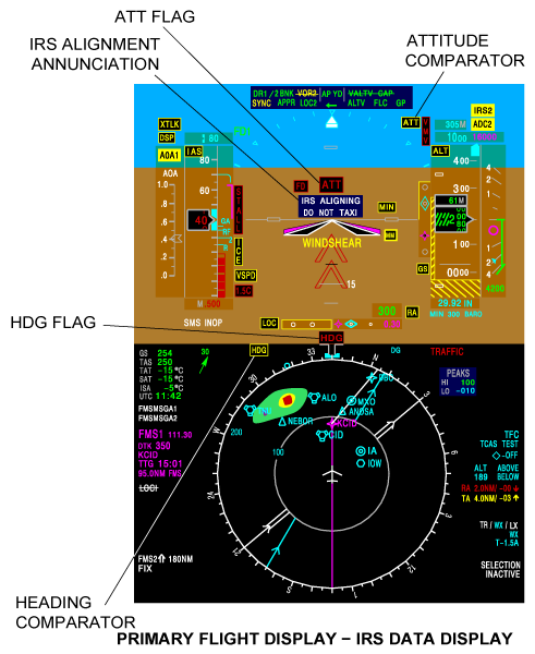
IRS Alignment Mode Display
During IRU 1 or IRU 2 alignment on ground, the message 'IRS ALIGNING DO NOT TAXI' is displayed. If the IRS alignment occurs during flight, the message 'IRS ALIGNING' is displayed.
Attitude and Heading Display
The attitude display gives the relation between the aircraft pitch and roll, and the horizon. The attitude display shows a racetrack sky/ground attitude sphere.
The horizon line divides the sky (blue) and the ground (brown). The aircraft symbol is centered on the attitude sphere. The aircraft V-bar symbol is a stationary chevron marker that gives the relation between the flight-director steering commands and the pitch/roll attitudes.
The heading display gives the relation between the aircraft centerline and the magnetic north pole.
The crew alerting system (CAS) message that follows is related to the attitude and heading reference system:
| CAS Messages | Type | Description | Color |
| IRS 1 IN ATT | Status | IRU 1 is in Attitude mode. | White |
| IRS 2 IN ATT | Status | IRU 2 is in Attitude mode. | White |
Reversion Mode Display
Alternate and common annunciators are displayed to alert the pilots that the same data source is being displayed on both PFDs for IRS and/or ADC, or that an alternate (other than normal) source has been selected (IRS 3). These annunciations are IRS 1 or IRS 2 (for dual IRS aircraft). In dual IRS installations, the common source annunciator is a IRS 1 or IRS 2 (depending on the IRS sensor selected) in black letters inside an inverse video yellow box.
Message disappears if the selector switch is in NORM position.


12/08/15
System Interface
APM
The APM is an Electronically Erasable Programmable Read-Only Memory (EEPROM) device that may be transitioned to a low-power mode when not in use, by means of its Chip Select (CS) line.
Each APM interfaces with only one IRU, which is its sole provider of power. It is wired directly to that IRU (RS-232 interface) and provides no other interface to another device in the aircraft. The IRU provides power to the APM upon power-up, and the power is maintained while the IRU is in its operational state.
Adaptive Flight Displays (AFD)
IRU 1 uses its L-IRS-2 output bus to interface with the on-side displays (PFD1 and MFD1) and its L-IRS-3 output bus to interface with the offside displays (PFD2 and MFD2).
IRU 2 uses its R-IRS-2 output bus to interface with the on-side displays (PFD2 and MFD2) and its R-IRS-3 output bus to interface with the offside displays (PFD1 and MFD1).
Synthetic Vision Computer (SVC)
SVC receives data solely from IRU 1 via L-IRS-4 output bus and from IRU 2 via R-IRS-4 output bus.
Input Output Concentrator (IOC)
Some of the aircraft components like Data Concentrator Unit (DCU), Terrain Awareness Warning System (TAWS), Maintenance Diagnostic Computer (MDC) and Fuel Quantity and Gauging Computer (FQGC) needs IRS data, but they are not directly connected to IRUs and, they receive the required IRS data via the IOCs. DCU receives. IRU 1 uses its L-IRS-1 output bus to interface with L-IOC and IRU 2 uses its R-IRS-1 output bus to interface with R-IOC which in turn supplies IRS data to DCU, TAWS, MDC and FQGC. On the other hand, the IRUs use data from the ADCs and FMCs,also they are not connected directly to them. The IRU 1 and 2 use their L-IRS-1 and R-IRS-1 buses to provide data to the IOCs and utilizes L-GPBUS-5 and R-GPBUS-5 buses to receive data from IOCs.
GPS INTERFACE
LRVI receives GPS ARINC 429 (L/R-GPS-3) data and RS422 Time Mark direct from the two GPS receivers.
GPS RS 232 Time Mark Interface
The IRUs receive RS-422 GPS L-Time Mark 3 and R-Time Mark 3 buses. The time mark circuits are used to synchronize the IRU to the GPS time base, where the time mark pulses occur at a nominal rate of once per second and the resolution of this synchronization logic is 100 ms or less. The IRU selects the time mark from the same GPS input source (1 or 2) as the received ARINC data.
GPS ARINC 429 Interface
The LRVI receives inputs from two GPS Receivers on high-speed ARINC 429 input buses: L-GPS-3 and R-GPS-3.
Note 1:
The User Range Accuracy (057) is an optional data label which might not be transmitted by all GPS receivers. While User Range Accuracy is used by the Hybrid function, if it is received, it is not a required input.
Note 2:
These labels are optional.
Note 3:
These data values have been divided into two parts and are received in two separate data labels (coarse and fine). The fine data component needs to be concatenated with the coarse data component to generate the whole data value used by the device.
Note 4:
UTC data is received on two labels; coarse data (label 150) and fine data (label 140). The data from labels 150 and 140 are concatenated to produce the whole data value used by the device. UTC reflects the Coordinated Universal Time at the Time Mark instant; UTC is applicable at the rising edge of the Time Mark signal.

12/08/15
System Monitoring
The IRS has built-in self-test functions that monitor the operating conditions of the system. Caution annunciations and warning flags show on the PFD display to tell the flight crew that there are fault and/or fail conditions in the IRS system.
The IRU starts a functional test of its outputs at the same time with other modes when it receives a functional test command and occurrence of some conditions specifically to a mode of operation. The IRU receives the functional test command from the functional test discrete input or the functional test command on one of the ARINC input buses. To start the functional test, the IRU must meet these conditions:
- The IRU is in the navigation mode and the ground speed is less than 20 ±0.1 kts.
- The IRU is on the ground and in the alignment or attitude mode, and there is not much aircraft motion.
The possible PFD displays for the IRS includes the ATT and HDG flags, PIT and ROL annunciations.
Note:
On the PFD display, only the flags and annunciations identified are related to the IRS and are described in the paragraphs that follow. The other flags and annunciations shown on the PFD display are described in their related systems.
ATT (Attitude) Flag
If the PFD senses an attitude input fail-condition, the red ATT (in a red box) attitude flag shows on the PFD.
HDG (Heading) Flag
If the heading sensor input fail-condition is sensed, the heading flag (red HDG in a red box) shows on the PFD.
HDG (Heading) Comparator
The yellow HDG (in a yellow box) heading comparator shows when the difference between the pilot and copilot heading is more than 6 degrees. The HDG comparator shows in the middle of the PFD.
ATT (Attitude) Comparator
The yellow ATT (in a yellow box) attitude comparator shows on the PFD, for the conditions that follow:
- Difference between the pilot and copilot pitch and roll is more than 3 degrees when glideslope capture.
- Difference between the pilot and copilot pitch and roll is more than 4 degrees when not glideslope capture.
ROL (Roll) and PIT (Pitch) Comparator
The yellow ROL (in a yellow box) roll comparator shows on the PFD, for the conditions that follow:
- Difference between the pilot and copilot pitch and roll is more than 3 degrees when glideslope capture.
- Difference between the pilot and copilot pitch and roll is more than 4 degrees when not glideslope capture.


MFD Annunciations
True Heading Mode
“ TRUE” is displayed in cyan, when referenced to true heading.
Failure Indications
A red “ HDG” flag is displayed if the IRS Heading fails.
Note:
The MFD page shown is for reference only to show the IRS display data. In normal operation, the information shown in the figure can not be displayed simultaneously, as shown.
FMS Annunciations
When the IRUs are aligning, the Time to Nav is displayed on the FMS CDU POS INIT 3/3 page. The IRUs are completely aligned when Time to Nav reaches zero.
If the IRU is restarted while in the air, it enters reversionary attitude mode followed by Alignment In Motion (AIM) mode. During this period, “ SET IRS HDG” is posted, allowing the pilots to enter HDG via the FMS CDU until the IRS transitions to AIM Attitude. After the necessary integrity tests pass, the IRU enters the AIM Attitude mode, in which it computes true and magnetic heading without a requirement for a “ SET IRS HDG” input entry.
10/20/20
Component Location Index
| Component Location Index | |||
|---|---|---|---|
| IDENT | DESCRIPTION | LOCATION | IPC REF |
| A233 | INERTIAL REFERENCE UNIT (LH) | ZONE(S) 221 | 34-45-01 |
| A232 | INERTIAL REFERENCE UNIT (RH) | ZONE(S) 222 | 34-45-01 |
| - | INERTIAL REFERENCE UNIT TRAY (LH) | ZONE(S) 221 | 34-45-05 |
| - | INERTIAL REFERENCE UNIT TRAY (RH) | ZONE(S) 222 | 34-45-05 |
| A237 | AIRCRAFT PERSONALITY MODULE (LH) | ZONE(S) 221 | 34-45-09 |
| A236 | AIRCRAFT PERSONALITY MODULE (RH) | ZONE(S) 222 | 34-45-09 |