


Overview
The VHF navigation (VHF NAV) system gives the VHF omnidirectional range (VOR), instrument landing system (ILS), and automatic direction finder (ADF) navigation functions that follow:
- The VOR function gives the position fix and shows the direction to the navaids on the airways
- The ILS function gives the aircraft approach to a runway and puts the aircraft at the correct altitude and course for a landing
- The ADF function shows the direction to a ground station
On A/C Pre SB 350-34-001, the VHF navigation system has dual very-high-frequency (VHF) navigation-receivers and one ADF receiver.
On A/C Post SB 350-34-001, the VHF navigation system has dual very-high-frequency (VHF) navigation-receivers with dual ADF receivers.
The VHF NAV system receives and monitors the VOR, ILS localizer/glideslope (LOC/GS), and marker beacon signals. The VOR signals give the en route navigation and terminal-area guidance data. The ILS LOC/GS signals give the approach and landing guidance data. The marker beacon signals give distance-to-runway data. The VHF NAV system gives the station identification digital-audio of the VOR/LOC and marker beacon, to the radio interface unit (RIU).
The pilot and copilot primary flight displays (PFD) and multi-function displays (MFD) show the VOR and LOC/GS data. The pilot and copilot PFDs show the marker beacon annunciations. The ADF receiver calculates the bearing direction to the ground station.
03/30/22
VHF Navigation Receiver
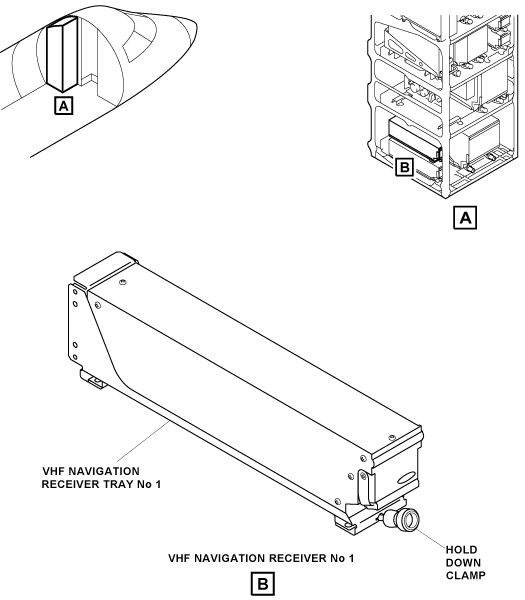
The VHF navigation system has two VHF navigation receivers. VHF navigation receiver No. 1 is installed in a mounting tray, in the LH equipment rack. VHF navigation receiver No. 2 is installed in a mounting tray, in the RH equipment rack. The receiver front panel has a swivel handle to help remove the receiver from the mounting tray. Each VHF NAV receiver is fully digital and includes three or four different receivers:
- VOR/LOC receiver
- Glideslope receiver
- Marker beacon receiver
- ADF receiver
On A/C Pre SB 350-34-001, for the single ADF installation, only the VHF navigation receiver No. 1 has an ADF receiver.
On A/C Post SB 350-34-001, for dual ADF installation, each of the two VHF navigation receivers has an ADF receiver.
The two VHF NAV receivers have continuous self-test functions, and automatically report fault conditions to the maintenance diagnostic computer (MDC). The diagnostic words go through the RIUs and the input/output concentrators (IOCs) of the integrated-avionics processing system (IAPS), to the MDC. Also, when the receiver has a fault condition, its monitor function sends data to the PFDs and MFDs to remove the applicable displays and/or to show the applicable warning flags.
The VOR/LOC receiver operates in the frequency ranges that follow:
- The VOR frequencies are the even frequencies from 108.0X to 112.0X MHz and all frequencies from 112.0X to 117.9X MHz
- The localizer (LOC) frequencies, in pairs with glideslope (GS) frequencies, are the odd frequencies from 108.1X to 111.9X MHz
The frequencies of the distance measuring equipment (DME) are usually in pairs with the VOR/LOC frequencies. When the DME is not set to the hold mode, selection of a VOR/LOC frequency will automatically do the selection of the related DME frequency. In the hold mode, the DME is tuned independently.
The glideslope receiver operates in the frequency range of 329.15 to 335.00 MHz. The marker beacon receiver operates at a frequency of 75.00 MHz. The ADF frequencies are from 190.0 to 1,799.0 MHz or the extended frequency range from 190.0 to 1,799.0 MHz and 2,179.0 to 2,185.0 MHz.

12/11/15
VHF Navigation Receiver Tray
The VHF navigation system has two VHF navigation receiver trays installed in the equipment racks. The VHF navigation receiver tray No. 1, in the LH equipment rack, holds the VHF navigation receiver No. 1. The VHF navigation receiver tray No. 2, in the RH equipment rack, holds the VHF navigation receiver No. 2.
One hold-down clamp on the tray engages the hold-down hook on the receiver and attaches the receiver to the tray. The connector at the rear of the tray gives the interface from the receiver to the aircraft system wiring.
12/11/15
VOR/LOC Antenna Coupler
The VHF navigation system has one VOR/LOC antenna coupler. The VOR/LOC antenna coupler is a hybrid phasing coupler. This type of coupler is used with a balanced-loop antenna configuration. The balanced-loop antenna configuration gives stronger signals to the VHF navigation receivers.
The coupler operates as a coupler and a diplexer. The signals received from the two VOR/LOC antennas are mixed and given to the two VHF navigation receivers. The VOR/LOC antenna coupler is installed in the vertical stabilizer at the VOR/LOC antenna level.


12/11/15
VOR/LOC Antenna
The VHF navigation system has two VOR/LOC antennas. The VOR/LOC antennas receive signals from the VOR or localizer transmitters on the ground. The VOR/LOC antennas are horizontally polarized. Together with the VOR/LOC antenna couplers, the VOR/LOC antennas supply omnidirectional operation.
The VOR/LOC antenna No. 1 is installed on the left side of the vertical stabilizer below the horizontal stabilizer. The VOR/LOC antenna No. 2 is installed on the right side of the vertical stabilizer below the horizontal stabilizer.


12/11/15
Marker Beacon Antenna
The VHF navigation system has two marker beacon antennas. The marker beacon antennas receive signals from the outer, middle, and inner marker-beacon transmitters on the ground. The marker beacon antennas are horizontally polarized.
The marker beacon antennas are installed at FS781.00 on the bottom of the aft fuselage directly below the engine pylons. The marker beacon antenna for the VHF NAV receiver No. 1 is on the left side. The marker beacon antenna for the VHF NAV receiver No. 2 is on the right side.
![]()
12/11/15
Glideslope Antenna
The VHF navigation system has one glideslope antenna. The glideslope antenna receives glideslope signals from the glideslope transmitter on the ground. The glideslope antenna is horizontally polarized and has two connectors to give signals to the two glideslope receivers.
The glideslope antenna is installed in the nose radome at FS220.00 below the weather radar assembly.


12/11/15
Automatic Direction Finder Antenna
The VHF navigation system has one ADF antenna for the ADF receiver.
For the dual ADF receivers, the VHF navigation system has a dual ADF antenna.
Post SB 350-34-001, the ADF antenna has a low-drag housing that contains two sense antennas , two loop antennas, and a radio frequency (RF) amplifier module. The dual antenna has two amplifier modules. The two loop antennas are installed 90 degrees apart, and together with the sense antennas they find the relative bearing to a ground station. The electrical connections are made with a multi-pin connector. The RF amplifier module gives the 50 W signal through a terminated, non-critical length of 50 ohm coaxial cable. The ADF antenna is installed at FS515.00 on the top of the fuselage.
For A/C Pre SB 350-34-001, the ADF antenna is single sense antenna.

Operation
The VHF navigation receiver includes in a one unit a VOR/LOC receiver, a glideslope receiver, a marker beacon receiver, and an ADF receiver. Audio signals are sent to the audio integrating system through the RIUs. Navigation data is sent to the PFDs and MFDs through the integrated-avionics processor system (IAPS). The VHF NAV receivers are tuned with the pilot and copilot MFDs or the control display units (CDUs).
VOR Operation
In the VOR operation, the VHF NAV receivers monitor the VOR signals, from the VOR station selection, along the flight path. The receivers give VOR bearing data to the PFDs and MFDs through the IAPS. Also, the VHF NAV receiver gives the VOR station-identification audio-signal to the control panel electronic (CPE). The CPE gives the audio signal to the flight compartment speakers or the pilot and copilot headsets.
ILS Operation
In the localizer/glideslope (or ILS) operation, the VHF NAV receivers monitor the localizer and glideslope signals from the localizer station selection and the related glideslope station. When the navigation receiver tunes a localizer frequency, the glideslope frequency is automatically tuned. The VHF NAV receivers monitor the localizer signal to calculate the horizontal deviation and signal validity status. The receivers monitor the glideslope signal to calculate the vertical deviation and signal validity status. The localizer and glideslope deviation outputs are supplied to the pilot and copilot PFDs and MFDs, through the IAPS.
Marker Operation
The marker beacon receiver is a tuned radio-frequency receiver. It receives a pulsed tone when the aircraft is above one of the marker beacon transmitters installed at the threshold of a runway. The marker tone is different for the three possible (inner, middle, or outer) markers.
ADF Operation
The ADF receiver calculates the bearing direction with the direction-of-arrival of a radio wave from the ground station. The ADF function shows the direction to a ground station with relation to the aircraft center line.

Controls and Displays
The control/display functions for the VHF navigation system are supplied to the flight crew through:
VHF Navigation Displays
Navigation Data
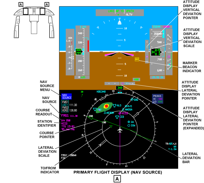
The navigation data (navigation source indicator, course display, distance display, and station identifier) are set with the NAV SRC pushbutton on the pilot and copilot DCPs. The navigation data shows on the left side of the related pilot or copilot PFDs. The same-side navigation data shows in green, and the opposite-side navigation data shows in yellow.
The navigation (NAV) source display shows the active NAV source and a digital course readout. If the NAV data is not valid, the NAV source indicator changes to red letters in a red box.
The digital course (CRS) readout shows the course through the navaid station selection or next way point. The station identifier shows the four-letter identification of the navaid station. The time-to-go (TTG) in minutes and the distance (in nautical miles) to the tuned navaid or next way point shows below the station identifier.
Navigation Source Menu
The NAV SRC pushbutton, on the DCP, shows the NAV SOURCE menu on the PFD. The NAV SOURCE menu shows the navaids that can be set as the active NAV source. The possible selections are VOR1, VOR2, LOC1, LOC2, FMS1, or FMS2. With the NAV SRC pushbutton, you can move the NAV source selection to the next available NAV source on the NAV SOURCE menu. The larger cyan letters show the active NAV source. The smaller white letters show the other available NAV sources. The active NAV source controls the course pointer display.
Course Selection and Indication
The VOR or localizer course data are shown on the pilot and copilot PFDs and MFDs. The course selection is done with the CRS 1 or CRS 2 button on the flight guidance panel (FGP) on the glareshield. Course is displayed with a pointer and a digital indication.
The course pointer shows the angular position of the course selection on the compass rose. The course digital indication (CRS XXX), on the left side of the pilot and copilot PFDs, shows the course selection in degrees. The lateral deviation bar shows the aircraft deviation from the VOR or localizer beam selection. When the aircraft is on course, the lateral deviation bar aligns with the course pointer.
The course pointer is a solid-line, triangle-head pointer (or the straight-line tail). The course pointer shows the active NAV course. The course display shows a digital readout of the active NAV course. The TO/FROM symbol shows "to" or "from" direction of the navaid or way point. The TO/FROM symbol moves as a part of the course pointer. The triangle symbol points toward the tuned station or next way point.
The TO indication shows a triangle that points to the head-side of the course deviation bar. The FROM indication shows a triangle that points to the tail-side of the course deviation bar. The TO/FROM indication shows in the same color as the related navigation source.
On the MFD map-mode page, a solid line on the course vector shows the TO indication of the VOR navaid selection. A dashed line on the course vector shows the FROM indication. The course vector shows in the same color as the navigation source selection.
VOR Lateral Deviation
The aircraft lateral deviation from the VOR beam shows on the pilot and copilot PFDs and MFDs. The lateral deviation bar (the center part of the course pointer) moves left or right from the pointer head and tail to show the quantity of lateral deviation from the active NAV course. The quantity of deviation is read against the lateral deviation scale. The bar aligns with the head and tail to complete the pointer when the aircraft is on course.
The lateral deviation scale has four dots that show perpendicular to the lateral deviation bar. Two dots show on each side of the aircraft symbol. Each dot on the lateral deviation scale shows a 5 degrees displacement from the VOR beam center.
The lateral deviation scale shows in white, and the lateral deviation bar shows in the same color as the related navigation source.
LOC Lateral Deviation
The aircraft lateral deviation from the localizer beam is shown on the pilot and copilot PFDs and MFDs.
The lateral deviation bar (the center part of the course pointer) shows the aircraft lateral deviation. The lateral deviation bar moves from side to side, perpendicular to the lateral deviation scale.
Each dot on the lateral deviation scale shows a 75 μA (0.0775 ddm) displacement from the localizer beam center. The lateral deviation scale shows in grey. The lateral deviation bar and the lateral deviation pointer show in the same color as the related navigation source.
The localizer lateral deviation scale shows when the active NAV source is LOC. The aircraft lateral deviation from the localizer beam shows on the pilot and copilot PFDs. A diamond-shaped pointer that moves left and right on the lateral deviation scale shows the aircraft lateral deviation.
When the localizer lateral deviation pointer moves out of the scale limits, half of the lateral deviation pointer (the part that points to the center of the scale) is removed.
If an invalid or a no-computed-data lateral-deviation input is received, the localizer-deviation flag (a red LOC in a red box) comes into view. When the LOC flag shows, the lateral deviation pointer and scale are removed from view.
Expanded LOC Lateral-Deviation
The expanded localizer-lateral-deviation scale shows when the active NAV source is LOC and the two PFD category-II conditions are correct.
The aircraft lateral deviation from the localizer beam shows on the pilot and copilot PFDs. A diamond-shaped pointer that moves left and right on the expanded lateral deviation scale shows the aircraft lateral deviation.
Each square on the expanded lateral deviation scale shows a 0.0258 ddm displacement from the localizer beam center.
The expanded lateral deviation scale shows in grey, and the lateral deviation pointer shows in the same color as the related navigation source.
Excessive Lateral Deviation
During a precision approach (between 600 ft (182.9 m) and RA MIN), the lateral deviation bar and scale flash yellow if an excessive lateral deviation condition is found. If one of the PFDs senses the condition, the lateral deviation bar and scale flash on all the PFDs and MFDs. The lateral deviation bar and scale flash until the excessive deviation condition is corrected.
The excessive-lateral-deviation indicator warning shows when the excessive deviation condition is found, and is removed when the condition is corrected. Operation of the pilot or copilot master warning/caution switch/light, on the WARNING/CAUTION panel, does not cause the indication to go off.
The conditions to get the excessive lateral-deviation indication are as follows:
- Aircraft on the glideslope path
- Enable logic for the LOC (localizer) comparator is correct
- Radio altitude is correct and shows between 600 ft (182.9 m) and RA MIN
- Lateral deviation is more than 25 μA or an excessive lateral-deviation condition is found by one of the PFDs
Pilot/Copilot Side Data-Difference
The two VHF NAV receivers give localizer and glideslope data to the pilot and copilot displays. The PFDs and MFDs compare the left and right side data to make sure that each pilot has the same data.
If the localizer data, from the VHF NAV receivers, does not agree in tolerances, a yellow LOC in a yellow box, flashes on the pilot and copilot PFDs. If the glideslope data, from the VHF NAV receivers, does not agree in tolerances, a yellow GS in a yellow box, flashes on the pilot and copilot PFDs.
Vertical Deviation
The aircraft vertical deviation from the glideslope beam shows on the pilot and copilot PFDs, to the right of the attitude display sphere. A diamond shaped pointer shows the aircraft vertical deviation from the glideslope. The pointer moves up and down on the vertical deviation scale.
Each dot on the vertical deviation scale shows a 0.0875 difference of depth of modulation (ddm) displacement from the glideslope beam center. The vertical deviation scale shows in grey, and the vertical deviation pointer shows in the same color as the related navigation source. When the vertical deviation pointer moves out of the scale limits, half of the vertical deviation pointer (the part that points to the center of the scale) is removed.
If an invalid or a no-computed-data vertical-deviation input is received, the glideslope-deviation flag (the red letters GS (glideslope) in a red box) comes into view. When the GS flag shows, the vertical deviation pointer and scale are removed from view.
Excessive Vertical Deviation
During a precision approach (between 600 ft (182.9 m) and RA MIN (radio altitude minimum), the vertical deviation pointer and scale flash in yellow, if an excessive glideslope-deviation condition is found. The vertical deviation pointer and scale flash on the pilot and copilot PFDs, if one of the two PFDs senses an excessive deviation condition. The vertical deviation pointer and scale flash until the excessive deviation condition is corrected.
The excessive vertical-deviation indication warning shows when the excessive deviation condition is found, and is removed when the condition is corrected. Operation of the pilot or copilot master warning/caution switch/light, on the WARNING/CAUTION panel, does not cause the indicator to go off.
The conditions to get the excessive vertical-deviation indication are as follows:
- Aircraft on the glideslope path
- Enable logic for the glideslope comparator is correct
- Radio altitude is correct and shows between 600 ft (182.9 m) and RA MIN
- Vertical deviation is more than 75 μA or an excessive vertical-deviation condition is found by one of the PFDs
Marker Beacon Indications
In the marker beacon operation, the VHF NAV receivers supply a visual and aural indication of the aircraft relation to the runway threshold. The marker beacon signals are amplitude-modulated (AM) 75 MHz signals. The approach to the runway has three marker beacon transmitters (outer, middle, and inner).
The receivers monitor the signals sent by the marker beacons as the aircraft goes into the related marker beacon beam. The pilot and copilot PFDs show the letters OM, MM, or IM in a box when the aircraft is over that marker beacon. The sensitivity of the marker beacon receiver can be adjusted to a high- or low-level with the MFD NAV CONTROL menu. The larger letters show the set HI or LO sensitivity level on the MFD NAV CONTROL menu.
The marker beacon indicator shows the letters OM (outer marker) in a box, the letters MM (middle marker) in a box, or the letters IM (inner marker) in a box.
Bearing Source Indications
In the VOR operation, two different bearing sources can show at the same time. They are identified as the number 1 and number 2 bearing pointers. The number 1 bearing pointer has a one-line pointer. The number 2 bearing pointer has a two-line pointer. The bearing pointer gives the pilot a visual indication of the physical location of the bearing station related to the present position of the aircraft.
The bearing pointer position is geometrically correct and does not change with the magnetic or true heading selection. The number 1 bearing pointer gives navigation data from the left side source. The number 2 bearing pointer gives navigation data from the right side source. The bearing pointers are set from the BRG SOURCE menu on the PFD. The BRG SRC pushbutton, on the DCP, shows the BRG SOURCE menu on the PFD. The selection box shows around the bearing-pointer menu used last.
When you turn the MENU button, on the DCP, you move the selection box to the number 1 or 2 bearing-pointer menu. You must turn the DATA button to set the bearing source or OFF in the selection box. The larger cyan letters show the active bearing source. The smaller white letters show the other available bearing sources.
The possible number 1 bearing-pointer selections are FMS1, VOR1, ADF1, or OFF. The possible number 2 bearing-pointer selections are FMS2, VOR2, or OFF. For the dual ADF, the possible number 2 bearing-pointer selections are FMS2, VOR2, ADF2, or OFF.
The bearing-source indicators show in the lower left corner on the PFDs and MFDs. The number 1 bearing-source indicator shows in cyan, and the number 2 bearing-source indicator shows in white. The bearing identification shows the station identifier or frequency of the VOR or ILS, the way point of the FMS, or the frequency of the ADF. The bearing identification shows below the bearing source annunciation. The letter T follows the bearing identification when the bearing source is VOR and true heading is set.
The bearing icons are small bearing pointer symbols that are used to relate the bearing source annunciations to the individual pointers. A one-line bearing icon shows adjacent to the number 1 bearing-source annunciation. A two-line bearing icon shows adjacent to the number 2 bearing-source annunciation.
The distance to the FMS or VOR bearing source selection shows when the bearing source is not the same as the active navigation source. The bearing distance readout shows to the right of the bearing icon. When the PFD shows unusual attitude, the number 1 and 2 bearing-pointer distance readouts go off.


MFD/DCP Controls and Displays
The MFD/DCP radio-tune procedure is the usual procedure to tune the VHF navigation receivers. The VHF navigation receivers are tune with the applicable DCP controls, in relation to the MFD displays that follow:
- MFD radio menu
- MFD NAV 1 (2) control menu
- MFD ADF 1 (2) control menu

MFD Radio Menu
The pilot and copilot display-control-panels and MFDs give control of the same-side and opposite-side radios. The MFD radio menu shows the same-side radio primary controls along the bottom of the MFD. One radio function at a time, can be set with the selection box.
The selection box is a cyan box that can be positioned around a radio function with the MENU button. When the selection box is around a tune frequency, the cyan transfer arrow symbol shows on the right side of the box. To transfer the preset frequency to the active frequency, you must push the transfer button on the DCP. When the selection box is around a tune frequency or channel, the TUNE buttons on the DCP, change the frequency. The large TUNE button tunes the most significant digits, and the small TUNE button tunes the least significant digits.
When you turn the MENU button, on the DCP, you can move the selection box. The DATA button changes the numbers in the selection box. The PUSH SELECT button sets or does not set the value in the selection box. The 1/2 pushbutton on the DCP shows the No. 1 side radio-menu or the No. 2 side radio-menu.
The NAV display shows the active NAV frequency and the preset NAV frequency. The digit to the right of the NAV legend (1 or 2) identifies the left (No. 1) or right (No. 2) navigation radio. The NAV active frequency shows the VHF NAV-receiver frequency. When the selection box is around a frequency, you must turn the TUNE buttons on the DCP, to change the frequency. When the selection box is around the preset frequency, the transfer arrow shows to the right of the preset frequency. When you push the transfer button, on the DCP, you move the preset frequency to the active frequency.
On A/C Pre SB 350-34-001, the ADF display shows the active ADF frequency and the preset ADF frequency. The ADF active frequency shows the ADF receiver frequency. When the selection box is around a frequency, and you turn the TUNE button on the DCP, you change the frequency. When the selection box is around the preset frequency, the transfer arrow shows to the right of the preset frequency. To move the preset frequency to the active frequency, you must push the transfer button on the DCP.
On A/C Post SB 350-34-001, the ADF display shows the active ADF frequency and the preset ADF frequency. The ADF active frequency shows the ADF receiver frequency. The digit to the right of the ADF legend (1 or 2) identifies the left (No. 1) ADF or right (No. 2 ) ADF. When the selection box is around a frequency, and you turn the TUNE button on the DCP, you change the frequency. When the selection box is around the preset frequency, the transfer arrow shows to the right of the preset frequency. To move the preset frequency to the active frequency, you must push the transfer button on the DCP.
The MFD radio menu gives access to other control/display menus for the VHF navigation system as follows:
- When the selection box is around a NAV frequency, and you push the RADIO pushbutton, on the DCP, the MFD NAV CONTROL menu shows
- When the selection box is around an ADF frequency, and you push the RADIO pushbutton, on the DCP, the MFD ADF CONTROL menu shows
MFD NAV CONTROL Menu
The AUTO tuning mode annunciation on the MFD NAV CONTROL menu shows when the FMS auto tune is enabled on the control display unit (CDU).
The DME HOLD display on the MFD NAV CONTROL menu shows the distance measuring equipment (DME) frequency. To set DME hold, push the DME H pushbutton on the DCP.
The MKR SENSE display on the MFD NAV CONTROL menu shows the marker beacon sensitivity selection. The MKR SENSE selection can be LO (low) or HI (high). The active mode shows in larger letters.
Moving the selection box to the TEST annunciation and pushing the PUSH SELECT button on the display control panel starts the test mode. TEST shows in larger letters while the test is active.
MFD ADF CONTROL Menu
The MODE display on the MFD ADF CONTROL menu, shows the ADF or ANT mode selection. The MODE selection shows in larger letters. The MODE selection can be ADF or ANT. The antenna mode operates as a VHF receiver and does not calculate the bearing to the tuned station.
The BFO display sets the beat frequency oscillator (BFO) OFF or ON. The BFO mode selection shows in larger letters. The ADF receiver mixes the BFO signal with the received ADF signal. The ADF receiver gives the audible beat note of the Morse code identifier of the non-directional beacon. When you move the selection box to the TEST annunciation, and push the PUSH SELECT button on the DCP, you start the test mode. TEST shows in larger letters while the test is on.


CDU Controls and Displays
The CDU radio tune procedure is a secondary procedure to tune the VHF navigation receivers. The control/display functions for the VHF navigation system are supplied with the following CDU pages:
- TUNE pages
- NAV 1 (2) CONTROL page
- ADF 1 (2) CONTROL page
TUNE Pages
The TUN (tune) key on the CDU, when pushed, shows the radio TUNE page 1/2. The NEXT function key, when pushed, gives an access to TUNE page 2/2. The radio TUNE pages are used to tune the communication and navigation radios and to control their operation modes. They also give access to CDU pages that give more radio control/display functions.
The TUNE page shows NAV1 and NAV2 labels. The flight crew tunes a NAV1 or NAV2 radio with the entry of a frequency, preset number, or station identification (such as CID) on the scratchpad line. Then, the flight crew pushes the NAV1 line-select key or the NAV2 line-select key to move this frequency to a data field. If the frequency is correct, it shows in the data field, and the radio is immediately tuned again. This is the VIR (VOR/ILS receiver) (also DME, unless DME HOLD is selected) frequency that is in operation. The digit to the right of the NAV legend (1 or 2) identifies the radio that is tuned to that frequency. MK-HI also shows adjacent to the NAV legend when marker beacon receiver sensitivity is set to high (HI). The flight crew pushes the NAV1 line-select key or the NAV2 line-select key again to see the related NAV CONTROL page.
The TUNE pages show ADF or ADF1 and ADF2 displays as applicable.
Note:
If only one ADF radio is installed, the ADF radio is shown and controlled on the first TUNE page. When TCAS is on and two ADF radios are installed, the active frequency for ADF 1 shows (but is not controlled) on the first TUNE page. All ADF 1 and ADF 2 radio control occurs on the second TUNE page.
To tune the ADF radio, the flight crew records a frequency or preset number on the scratchpad line. Then, the flight crew pushes the ADF line-select key to move this frequency to a data field. If the frequency is correct, it shows in the data field, and the radio immediately tunes again.
The flight crew pushes the ADF line-select key again to see the ADF CONTROL page. If two ADFs are installed, the flight crew pushes the ADF1 or ADF2 line-select key to see the related ADF CONTROL page. The digit to the right of the ADF legend (1 or 2) identifies the ADF radio that is tuned to that frequency, when two ADF receivers are installed. ANT shows adjacent to the ADF frequency when antenna mode is set. BFO (beat frequency oscillator) shows when BFO mode is set.

NAV 1 (2) CONTROL Page
The NAV 1 line-select key (on the TUNE page), when pushed, shows the NAV1 CONTROL page. The NAV 2 line-select key (on the TUNE page), when pushed, shows the NAV2 CONTROL page. The NAV1 CONTROL page is used as an example. The NAV 1 source annunciation shows that the CDU controls a No. 1 (left side) radio. This display shows the active frequency for the VHF NAV radio. This is the active frequency for VIR (also DME, unless DME HOLD is selected).
The flight crew records a frequency, preset number, or station identification on the scratchpad line. Then, the flight crew pushes the NAV line-select key to move this frequency to a data field. If the frequency is correct, the frequency shows in the data field, and the radio immediately tunes again. If the frequency is valid, but has no data, the frequency is shown in yellow (amber).
The correct NAV frequency limits are 108.00 - 117.95 MHz or extended DME frequency range 108.00 - 117.95 and 133.00 - 135.95 MHz. The NAV PRESETS numbers are 1 to 20. The DME HOLD line-select key, when pushed, causes the NAV frequency related to the DME channel to show on the display. HOLD shows adjacent to the hold frequency.
There is a MKR-SENS line-select key on the NAV control page which lets the flight crew set the marker sensitivity to low (LO) or high (HI) level. If the selection is set to HI, then a MK-HI display will show adjacent to the NAV source annunciation on the TUNE page.
The NAV TUNING line-select key is pushed to set the mode in which NAV is tuned. NAV is tuned automatically (AUTO) or manually (MAN). The tuning mode selection shows in large symbols. When MAN mode is set, the NAV radio is tuned again only when the flight crew makes an entry on the CDU. When AUTO mode is set, the NAV radio automatically tunes again because of commands from the FMS computer. The FMS tunes the NAV radio to en route stations through the flight, to keep correct position data.
The TEST line-select key, when pushed, starts the self-test of the VHF navigation system for 10 sec. The TEST annunciation becomes larger while the test is on. If the TEST INHIBITED annunciation is on, the line-select key cannot operate.
Note:
When the aircraft is in a critical navigation phase, the navigation system receives a tune/test inhibit input to stop all ILS tune changes and commanded self-tests. In this condition the TEST INHIBITED annunciation on the NAV CONTROL page is on.
The NAV PRESETS displays contain a maximum of 20 set NAV frequencies. The flight crew pushes the NEXT function key to show the subsequent preset page. The flight crew pushes the PREV function key to show the preset page that was on the display before. The flight crew pushes a preset line-select key to do the selection of a preset frequency and move it to the NAV active frequency data field.
To make or change a NAV PRESETS frequency, the flight crew records a frequency and/or identification on the scratchpad line. Then, the flight crew pushes the related numbered line-select key to move this frequency to a set frequency data field.
If the frequency is correct, the frequency shows in the data field. The frequency and the station identification show in the NAV data field (114.10/CID).

ADF 1 (2) CONTROL Page
The ADF, ADF1, or ADF2 line-select key on the applicable TUNE page, when pushed, shows the ADF CONTROL, ADF1 CONTROL, or ADF2 CONTROL page, respectively. The ADF1 CONTROL page is used as an example. On the ADF1 CONTROL page, the data below the ADF1 label shows the active frequency for the ADF radio No. 1. The flight crew records the frequency or preset number on the scratchpad line. Then, the flight crew pushes the ADF line-select key to move this frequency to a data field. If the frequency is correct, it shows in the data field, and the radio immediately tunes again.
The correct ADF frequency limits are 190.0 to 1799.0 kHz or extended ADF frequency range 190.0 to 1799.0 kHz and 2179.0 to 2185.0 kHz. The ADF PRESETS numbers are 1 to 20. The flight crew pushes the MODE line-select key to set ADF mode and then set ANT (antenna) mode. The larger annunciation shows the selection. In ADF mode, the radio supplies bearing-to-the-station and outputs that can be heard. In ANT mode, the radio supplies only an output that can be heard.
The flight crew pushes the BFO line-select key to set ON or to cancel OFF BFO mode operation. The larger annunciation shows the selection. When BFO is set, the ADF radio makes a 1 000 Hz BFO aural tone when a recorded continuous wave (cw) signal is received.
The TEST line-select key, when pushed, starts the ADF radio self-test procedure. The TEST annunciation becomes larger while ADF test is on. The ADF PRESETS displays contain up to 20 set ADF frequencies. The flight crew pushes the NEXT or PREV function key to show the preset page that was on the display before or the subsequent preset page. The flight crew pushes a preset line-select key to do the selection of a preset frequency and to move it to the NAV active-frequency data-field.
To make or change an ADF PRESETS frequency, the flight crew records a frequency and/or identification on the scratchpad line. Then, the flight crew pushes an applicable line-select key to move this frequency to the frequency data field. If the frequency is correct, it shows in the data field.

System Interface
The VHF navigation system has direct interfaces with the integrated standby instrument (ISI), radio interface units (RIUs), reversion select panel (RSP), and control display units (CDUs).
Integrated Standby Instrument (ISI)
The VHF NAV receiver No. 1 gives VHF NAV data, on an aeronautical radio incorporated (ARINC) 429 data bus, to the integrated standby instrument (ISI). The ISI receives VOR bearing, localizer deviation, and glideslope deviation on the L-NAV-VIR-1 low-speed (LS) data bus.
Radio Interface Units (RIUs)
The VHF NAV receiver No. 1 gives data, with two ARINC 429 high-speed (HS) data busses, to the RIU No. 1. The receiver gives the data, on the L-NAV-VIR-2 bus, that follows:
- VOR/ILS frequency (echo)
- VOR bearing
- Localizer deviation
- Glideslope deviation
- Equipment identification
- VHF navigation receiver diagnostic data
The receiver gives the data, on the L-NAV-ADF-2 bus, that follows:
- ADF frequency (echo)
- ADF bearing
- Digital audio
- Equipment identification
- ADF diagnostic data
The VHF NAV receiver No. 2 gives the same data to the RIU No. 2, on the HS data busses R-NAV-VIR-2 and R-NAV-ADF-2.
Audio Data
The VHF NAV receiver gives the VOR/LOC station-identification and marker beacon audio-signals (in a digital audio format), to the RIU. The RIU gives the digital audio data to the CPE (on LA-RIU-3 and LB-RIU-3 busses for the CPE No. 1 and on RA-RIU-3 and RB-RIU-3 busses for CPE No. 2). The CPE gives the analog audio signals to the flight compartment speakers or the pilot and copilot headsets.
When the third (observer) audio system option is installed, the CPE No.3 receives the digital audio data from the RIU No.1 (on LA-RIU-5 and LB-RIU-5 busses) and from the RIU No.2 on (RA-RIU-5 and RB-RIU-5 busses). The CPE No.3 gives the analog audio signals to the observer headset.
Guidance Data
In the localizer/glideslope (or ILS) operation, the VHF NAV receivers give final approach guidance data to the radio interface units (RIUs). The data includes the localizer and glideslope deviation signals. The RIUs give the guidance data to the input/output concentrators (IOCs) on the ARINC 429 HS data buses LA-RIU-6 and RA-RIU-6.
The IOC No. 1 gives the data on the ARINC 429 HS data bus (L-IOC-1) to the pilot and copilot PFDs and MFDs. The IOC No. 2 gives the data on the ARINC 429 HS data bus (R-IOC-1) to the pilot and copilot PFDs and MFDs. The L-IOC-1 and R-IOC-1 data busses are the primary inputs of VHF NAV data to the displays.
The RIUs also send secondary inputs of VHF NAV data to the pilot and copilot displays. The RIU No. 1 gives the data on an ARINC 429 HS bus (LB-RIU-6) to the pilot PFD and MFD. The RIU No. 2 gives the data on an ARINC 429 HS data bus (RB-RIU-6) to the copilot PFD and MFD. The LB-RIU-6 and RB-RIU-6 data busses give a secondary source of VHF NAV data to the pilot and copilot PFDs and MFDs.
Tune Data
The MFDs supply the primary radio tune function. The normal radio tune data path is from the MFD through the input/output concentrator (IOC) and the radio interface unit (RIU) to the VHF NAV receiver (port B). The display control panels (DCPs) supply interface to the radio tune controls.
The DCP No. 1 has the pilot interface to the radio tune controls. The DCP No. 1 gives data on an ARINC 429 HS data bus (L-DCP-2) to the pilot MFD. The MFD shows the radio tuning display. The pilot MFD gives data on an ARINC 429 HS data bus (L-MFD-1) to the IOC No. 1. The pilot MFD gives data on an ARINC 429 HS data bus (L-MFD-3) to the copilot MFD and RIU No. 2. The L-MFD-3 and R-MFD-3 data busses give cross-talk between the MFDs. The L-MFD-1 and L-MFD-3 data busses have the radio tune words that follow:
- Beacon code frequency
- ADF frequency
- VOR/ILS frequency
- DME frequency
- VHF communications tune word
The IOC No. 1 gives data on an ARINC 429 HS data bus (L-GPBUS-1) to the RIU No. 1 (channel B). The RIU is a dual-channel unit. The RIU channel B gives the tune data from the same-side MFD. The RIU channel A gives the tune data from the opposite-side MFD. The RIU No. 1 (channel B) gives data on an ARINC 429 HS data bus (LB-RIU-7) to the VHF NAV receiver No. 1 (port B).
The DCP No. 2 has the copilot interface to the radio tune controls. The DCP No. 2 gives data on an ARINC 429 high-speed data bus (R-DCP-2) to the copilot MFD. The MFD shows the radio tuning display. The copilot MFD gives data on an ARINC 429 HS data bus (R-MFD-1) to the input/output concentrator No. 2. The copilot MFD gives data on an ARINC 429 HS data bus (R-MFD-3) to the pilot MFD and RIU No. 1. The L-MFD-3 and R-MFD-3 data busses give cross-talk between the MFDs.
The R-MFD-1 and R-MFD-3 data busses have the radio tune data that follows:
- Beacon code frequency
- ADF frequency
- VOR/ILS frequency
- DME frequency
- VHF communications tune word
The IOC No. 2 gives data on an ARINC 429 HS data bus (R-GPBUS-1) to the RIU No. 2 (channel B). The RIU is a dual-channel unit. The RIU channel B gives the tune data from the same-side MFD. The RIU channel A gives the tune data from the opposite-side MFD. The RIU No. 2 (channel B) gives data on an ARINC 429 HS data bus (RB-RIU-7) to the VHF NAV receiver No. 2 (port B).
Reversion Select Panel
The reversion select panel (RSP) interface supplies reversion control functions. The RSP switches used for PFD/MFD display reversion and tune reversion are the LEFT DISPLAYS, RIGHT DISPLAYS, and TUNE switches.
When the switches are in the normal (NORM) position, each MFD tunes its same-side radios through the RIUs.
Display Reversion
The LEFT DISPLAYS switch positions are PFD REV, NORM, and MFD REV. When the LEFT DISPLAYS switch is set to the PFD REV or MFD REV position, the results that follow, occur:
- The PFD No. 1 or MFD No. 1 display turns off
- A discrete signal to the MFD No. 1 and PFD No. 1 prevents the radio tune function
- A discrete signal to the control display unit (CDU) No. 1 and No. 2 shows the MFD tune function is turned off
- A discrete signal causes the VHF NAV No. 1 to receive radio tune data from the input port A
The VHF NAV No. 1 receives radio tune data from the opposite-side MFD No. 2.
The copilot MFD gives data on an ARINC 429 HS data bus (R-MFD-3) to the pilot MFD and RIU No. 1 (channel A). The RIU No. 1 (channel A) gives data on an ARINC 429 HS data bus (LA-RIU-7) to the VHF NAV No. 1 receiver (port A).
The RIGHT DISPLAYS switch positions, on the reversion select panel, are PFD REV, NORM, and MFD REV.
When the RIGHT DISPLAYS switch is set to the PFD REV or MFD REV position, the results that follow, occur:
- The PFD No. 2 or MFD No. 2 display turns off
- A discrete signal to the MFD No. 2 and PFD No. 2 prevents the radio tune function
- A discrete signal to the control display unit No. 1 (and optional No. 2) shows the MFD tune function is turned off
- A discrete signal causes the VHF NAV No. 2 to receive radio tune data from the input port A
The VHF NAV No. 2 receives radio tune data from the opposite-side MFD No. 1.
The pilot MFD gives data on an ARINC 429 HS data bus (L-MFD-3) to the copilot MFD and RIU No. 2 (channel A). The RIU No. 2 (channel A) gives data on an ARINC 429 HS data bus (RA-RIU-7) to the VHF NAV No. 2 receiver (port A).
Tune Reversion
The TUNE switch positions, on the reversion select panel (RSP), are COM1 121.50, MFD ONLY, NORM, and CDU ONLY.
The MFD ONLY, NORM, and CDU ONLY positions are related to the VHF navigation system. When the TUNE switch is set to the NORM position, the MFD or control display unit tunes the VHF NAV receiver.
When the TUNE switch is set to the MFD ONLY position, a discrete signal stops the radio tune function of the control display unit.
When the TUNE switch is set to the CDU ONLY position, the results that follow, occur:
- A discrete signal to the MFDs and PFDs prevents the radio tune function from the DCP only
- A discrete signal causes the VHF NAV receivers No. 1 and No. 2 to receive radio tune data from the input port C
Control Display Units
The control display units (CDUs) interface supplies the secondary radio-tune function for the VHF NAV receivers. The control display unit No. 1 gives data on an ARINC 429 HS data bus (L-CDU-6) to the VHF NAV No. 1 receiver (port C).
The control display unit No. 2 gives data on an ARINC 429 HS data bus (R-CDU-6) to the VHF NAV No. 2 receiver (port C). If the optional control display unit No. 2 is not installed, the control display unit No. 1 tunes the right side radios. The control display unit No. 1 gives data on an ARINC 429 HS data bus (L-CDU-7) to the VHF NAV No. 2 receiver (port C).
Power Supply
The VHF NAV system receives power from a 28 VDC electrical source. The 28 V dc L ESS BUS supplies the VHF NAV receiver No. 1 through circuit breaker NAV1 on CB1-A1. The 28 VDC R MAIN BUS supplies the VHF NAV receiver No. 2 through circuit breaker NAV 2 on CB2-A1.

System Monitoring
The VHF NAV receiver has internal continuous diagnostics. The diagnostic word contains data on the status of specified internal functions. The diagnostic words are continuously transmitted to the maintenance diagnostic computer (MDC):
- Status data of the VHF NAV receivers are available on the MDC through the LRU INDEX/OPERATIONS page
- MDC records the diagnostic words and shows, when applicable, the fault messages on the CURRENT FAULTS page
Also, if a fail-condition occurs in the VHF NAV system, the VHF NAV frequency-display on the MFD is replaced with dashes. If the VHF NAV receiver is defective, the conditions that follow occur on the pilot and copilot PFDs and MFDs:
- Red navigation source indicator (in a red box) replaces the navigation source indicator
- Lateral deviation bar and scale go out of view
- TO/FROM indication goes out of view
Also, reception of unserviceable bearing data causes a red bearing source indicator (in a red box) to replace the bearing source indicator. The bearing pointer is removed.
10/20/20
Component Location Index
| Component Location Index | |||
|---|---|---|---|
| IDENT | DESCRIPTION | LOCATION | IPC REF |
| A47 | VHF NAVIGATION RECEIVER NO. 1 (LH) | ZONE(S) 221 | 34-51-01 |
| A48 | VHF NAVIGATION RECEIVER NO. 2 (RH) | ZONE(S) 222 | 34-51-01 |
| - | VHF NAVIGATION RECEIVER TRAY NO. 1 (LH) | ZONE(S) 221 | 34-51-05 |
| - | VHF NAVIGATION RECEIVER TRAY NO. 2 (RH) | ZONE(S) 222 | 34-51-05 |
| CP2 | VOR/LOC ANTENNA COUPLER | ZONE(S) 341 | 34-51-09 |
| E17 | VOR/LOC ANTENNA (LH) | ZONE(S) 341 | 34-51-13 |
| E18 | VOR/LOC ANTENNA (RH) | ZONE(S) 341 | 34-51-13 |
| E15 | GLIDESLOPE ANTENNA | ZONE(S) 110 | 34-51-17 |
| E21 | MARKER BEACON ANTENNA (LH) | ZONE(S) 330 | 34-51-21 |
| E16 | MARKER BEACON ANTENNA (RH) | ZONE(S) 330 | 34-51-21 |
| E22 | DUAL AUTOMATIC DIRECTION FINDER (ADF) ANTENNA | ZONE(S) 230 | 34-51-25 |
| E22 | SINGLE AUTOMATIC DIRECTION FINDER (ADF) ANTENNA | ZONE(S) 230 | 34-51-25 |