


Overview
The global positioning system (GPS) is a worldwide navigation system. The GPS system uses the NAVSTAR GPS satellite-constellation to calculate a very accurate three-dimensional position, three-dimensional velocity, and time. The aircraft has two GPS/global navigation satellite system (GNSS) systems and processes the transmissions from multiple GPS and wide area augmentation systems (WAAS) satellites simultaneously to calculate reliable navigation solutions based on all satellites in view.
A fully serviceable satellite constellation contains a minimum of 24 satellites with 21 satellites serviceable at all times. The satellites are put in orbit so that a minimum of six satellites are in view at all times. The GPS satellites move in a circle, above the same ground on the earth again and again, approximately one time each 12 h.
The GPS must receive a minimum of four satellites at the same time to calculate a satisfactory position, or three satellites and calibrated barometric altitude (baro-aiding). The GPS supplies (through the input/output concentrators units) continuous navigation data to the flight management system (FMS).
The GPS becomes the global navigation satellite system (GNSS) when satellite based augmentation system (SBAS) service provider data is accurate and in view and processed by the GPS-4000S correctly. The SBAS is an augmentation to the GPS which calculates GPS integrity and correction data on the ground, broadcasts this information using geostationary satellites to the GPS receiver, and then provides additional ranging signals for use to determine position, velocity, and time. The global navigation satellite system (GNSS) receiver (GPS-4000S) provides autonomous integrity monitoring (RAIM) for non-precision FMS approaches. The GPS also provides satellite based augmentation system (SBAS) data and predictive RAIM for non-precision FMS approaches at destination airports.
12/18/15
Global Positioning Receiver
The global positioning system has two global positioning receivers. The LH equipment rack has the GPS receiver No. 1. The RH equipment rack has the GPS receiver No. 2.
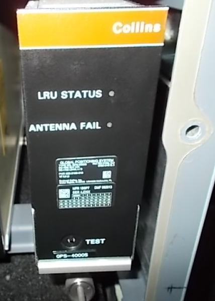
On the front panel, the GPS receiver has a TEST button and two light-emitting diodes (LEDs). The TEST button, at the bottom, is used to start self-test operation. The LEDs are used to supply operation status indication. The first LED (red/green), at the top, is for the GPS receiver status (LRU STATUS indicator). The second LED (red only), is for the GPS antenna condition (ANTENNA FAIL indicator). At the rear, the GPS receiver has an electrical connector used for the interface with the other aircraft systems.
The GPS receiver is a 12-channel and continuous-monitor GPS sensor that gets three-dimensional position from the NAVSTAR GPS. The GPS receiver uses the GPS L1 frequency (1575.42 MHz) signal. The L1 signal has coarse acquisition (C/A) code and navigation message modulation. The global positioning system can monitor as many as 12 satellites. Each GPS satellite has a different C/A code number.
The GPS receiver gives to the flight management system, the data that follows:
- Pseudo range measurements
- Delta range measurements
- Satellite position
- GPS receiver position
- GPS receiver velocity
- Measurement status
The receiver also keeps almanac and GPS data. The GPS receiver measures the distances, from the group of satellites in space, to calculate the location of the GPS receiver. When the GPS satellite transmits a signal, there is a specific time before the GPS receiver can receive the signal. This is because the signal must move through the distance between the satellite and the receiver. The GPS receiver uses the time period to calculate this distance. The satellite signal also has data about its location in space. This gives the receiver accurate points in space that it can use to calculate its location. The GPS measures the small change in the frequency of the received signals to calculate velocity.
The GPS-4000S receiver provides precise position, velocity, and time measurements for oceanic and domestic en route, terminal, approach (LNAV, LNAV/VNAV) and departure operations. The position, velocity, and time are computed by the GPS-4000S based on the satellite signals provided by the GPS satellite constellation. When in view, the GPS-4000S uses SBAS satellite signals to improve performance. The SBAS is an augmentation to the GPS which calculates GPS integrity and correction data on the ground.
The GPS is a one-way ranging system. The satellites transmit signals to the receivers. This one-way ranging system is possible only if the clock in the satellite and the clock in the receiver are synchronized. It is possible to align the clocks in the satellite and in the receiver with the time and the difference time. These times are contained in the GPS satellite signal.
The GPS receiver receives input signals for pressure and barometric altitude from the IAPS when poor satellite geometry or availability.


12/18/15
Global Positioning-Receiver Tray
The global positioning system has two GPS receiver trays. The LH equipment rack has the receiver tray No. 1. The RH equipment rack has the receiver tray No. 2. The receiver attaches to the GPS receiver tray. One hold-down clamp on the tray engages the hold-down hook on the receiver and attaches the receiver to the tray. The connector at the rear of the tray supplies the interface between the receiver and the aircraft system wiring. The receiver front panel has a swivel handle to help remove the receiver from the tray.
Global Positioning Antenna
The global positioning system has two global positioning antennas. The GPS antenna No. 1 is installed on the top middle of the forward fuselage, aligned with the forward edge of the passenger door. The GPS antenna No. 2 is installed on the top middle of the forward fuselage, aligned with the rear edge of the passenger door.
The GPS antenna is a small, hermetically sealed unit that receives the satellite signals. The signals go through an amplifier and a filter in the antenna before they are sent to the GPS receiver. The GPS receiver supplies the antenna preamplifier/filter with 12 VDC.

Operation
GPS Measurements
Measured Pseudo Range
The satellite continuously transmits an encoded signal. With this encoded signal, the GPS receiver calculates the range from the satellite to the aircraft. This measurement is pseudo range. This is not a correct range as there is always an unknown time difference between the receiver clock and the GPS system clock.
The GPS receiver calculates this unknown time difference. It calculates the difference with the algebra principle that, to find four unknown values, there must be no less than four equations/measurements.
Thus, the GPS receiver must monitor a minimum of four satellites and measure their pseudo range. These measurements are the inputs to a software algorithm that calculates the three unknown positions and the unknown GPS-receiver time difference. This is known as three-dimensional operation.
Pseudo Range Estimates
The GPS receiver calculates the errors between measured pseudo range and pseudo range estimates. The pseudo range estimates are calculated with satellite position data and the receiver position. The satellite position data is calculated from the orbit parameters. The orbit parameters are transmitted to the receiver from the satellite as a part of the navigation message.
Geometric Dilution of Precision (GDOP)
If there are four or more measurements available for the position solution, the GPS receiver possibly does not use them. The solution equation is very non linear and the precision of the solution is based on the geometry of the satellite configuration in use. Geometric dilution of precision (GDOP) is a calculated value that gives the quality of satellite geometry.
Receiver Autonomous Integrity Monitoring (RAIM)
The GPS receiver monitors the integrity of the satellites with receiver autonomous integrity monitoring (RAIM). RAIM does consistency checks of the satellite measurements. It will find and try to identify a defective satellite and remove it from calculations. Six satellites in view, or five satellites and calibrated barometric altitude (baro-aiding), are necessary for RAIM.
Satellite Based Augmentation System (SBAS)
The SBAS service providers can be disabled or enabled as required for approach procedures. In regions that service provider coverage overlaps, an approach be based on only one service provider. In this case, the other providers must be disabled from use. The SBAS-used approaches list the required service provider. If SBAS is listed, any provider is acceptable.
SBAS approaches have RAIM built into integrity and satellite fault functions.
Modes of Operation
Initialization Mode
The GPS receiver starts automatically when it receives 28 VDC power. The receiver first starts its internal computer, starts input/output operation, and does a built-in self-test. After 10 sec, the GPS receiver starts to transmit and receive data (through the IOCs) to and from the FMS, the inertial reference units (IRUs), and the air data computers (ADCs). When correct position, velocity, time, altitude and attitude data is received, the GPS receiver tries to find the satellite signals.
Acquisition Mode
To find the received satellite, the receiver makes the same course acquisition (C/A) code sequences for each satellite. It then aligns the received code with the C/A code it made until the two align. When two codes align, the receiver also knows the time the signal was transmitted from the satellite.
The travel time and range to the satellite are calculated with this time. Each satellite transmits a navigation message with data on its position and the positions of the other satellites. The navigation message contains the following data:
- Satellite time of transmission
- Satellite orbit data
- Difference between the satellite clock and the GPS system time
- Condition of the satellite
- Possible precision of the range measurements (propagation delay effects)
- Almanac data for the other GPS satellites
Acquisition mode tries to find and monitor the number of satellites necessary to let the receiver change into GPS navigation mode.
The GPS receiver time to first fix (TTFF) is no more than 75 sec if:
- The latitude and longitude is started in 2 km
- Time is started in 10 sec
- Velocity is known to ±10 m/sec
- There is correct almanac data
- The satellites are not unserviceable
The TTFF is not more than 10 min without correct position, time or almanac.
The receiver can change from acquisition mode to GPS navigation mode. This occurs when four or more correct C/A code pseudo ranges have been received.
GPS Navigation Mode
The GPS navigation (NAV) mode is the primary navigation mode for the en route, terminal, and non-precision approach flight phases.
Alt-Aided Mode
The altitude aided (alt-aided) mode is set from the GPS navigation mode. When the receiver senses bad satellite coverage or geometric conditions, the alt-aided mode includes altitude measurements.
The altitude measurements are included to increase the availability of fault detection and exclusion (FDE) and receiver autonomous integrity monitoring (RAIM).
The GPS receiver goes back to NAV mode when satellite coverage and geometric conditions make it possible.
If there are only three satellites (in the line of sight), the receiver uses the three-satellite pseudo ranges and altitude data from one more source (as a fourth measurement). The receiver does this to let the GPS receiver continue to calculate position. This is known as two-dimensional operation.
Test Mode
During usual operations there is a continuous internal monitor which occurs when time is available, but no less than every 5 sec.
Up to 256 faults can be kept in non-volatile memory (NVM) for 64 flights.
The GPS receiver has also a built-in self-test (BITE) that can be started with the TEST button on the GPS-receiver front panel. The test mode supplies fault isolation and maintenance aid functions.
Fail Mode
The GPS receiver can possibly sense a critical problem that would cause the navigation and time outputs to be not in limits. The GPS receiver then goes into FAIL mode.
12/18/15
Controls and Displays
The control and display functions for the GPS are supplied to the flight crew by:
- CDU GPS controls and displays
- FMS/GPS displays on the primary flight display (PFD) and multifunction display (MFD)
CDU GPS Controls and Displays
FMS GNSS CONTROL page
The IDX key on the CDU, when pushed, gives access to the INDEX page. The GPS CTL line-select key on the INDEX page, when pushed, shows the FMS GNSS CONTROL page. The GNSS CONTROL page is used to do the selection of a GPS sensor for position data, or to cancel use of GPS data.
When the FMS is permitted to use GPS position data, the ENABLED indication shows on the FMS GNSS CONTROL page, adjacent to one of the GPS names. When the FMS is not permitted to use GPS position data, the DISABLED indication shows adjacent to that GPS name. If the indication is DISABLED and the line select key related to that GPS name is pushed, the indication becomes ENABLED. If the indication is ENABLED and the line select key related to that GPS name is pushed, the indication becomes DISABLED.
The GNSS CONTROL page shows the position difference (POS DIFF) between each GPS sensor position and the FMS calculated position.
The POS DIFF data shows as dashes if data available to find the position difference is not sufficient.
The SAT DESELECT line-select key on the FMS CONTROL page, lets the flight crew remove manually a satellite from the RAIM calculations. The applicable satellite number is moved from the CDU scratchpad line to the data field below the SAT DESELECT legend. Then, the SAT DESELECT line-select key is pushed to remove the applicable satellite from the calculations.
The flight-destination way point (below the DEST label) and the related ETA (estimated time of arrival) data are given by the flight plan. The message below the APPR RAIM legend tells the flight crew that the GPS approach RAIM is unavailable (UNAVAIL).


LRN POS DATA Pages
The LRN POS DATA 1/2 page shows the current computed positions of each installed GNSS long range sensors and the FMS. When FREEZE is selected, all the data displays are captured or frozen. When UPDATE is selected, all the data displays are updated. The default value is UPDATE.
The LRN POS DATA 2/2 page shows the current computed positions of each installed IRS and the FMS. When FREEZE is selected, all the data displays are captured or frozen. When UPDATE is selected, all the data displays are updated. The default value is UPDATE.

GNSS STATUS 1/2 Page
The GNSS STATUS 1/2 page on the CDU shows status data for the applicable GPS receiver as follows:
- LATITUDE
- LONGITUDE
- TRUE TRACK ANGLE
- GROUND SPEED
- Satellite fault(s) - Shows if the satellite being used for a precision approach has a fault indication (SBAS).
- MODE
- FMS position difference
- GNSS HEIGHT
- GNSS ALTITUDE
- The number of satellites that the system uses at this time
GNSS STATUS 2/2 Page
The GNSS STATUS 2/2 page on the CDU shows status data for the applicable GPS receiver as follows:
- HAL - Horizontal Alert Limit. The HAL value varies based on the GNSS navigation mode.
- HPL - Horizontal Precision Limit. The HPL value comes from the GNSS sensor as data from the SBAS service provider.
- HFOM - Horizontal Figure of Merit.
- HUL - Horizontal Uncertainty Limit.
- SERVICE IN USE - Shows SBAS service providers in use (WAAS, EGNOS)
- APPR VAL - Approach vertical alert limit. The APPR VAL value comes from the FMS navigation database when the SBAS approach is selected.
- VPL - Vertical precision limit. The VPL value comes from the GNSS sensor when SBAS is used.
- VFOM - Vertical figure of merit.
- GNSS UNITS - Shows units of measurement in meters/feet on the CDU and the MFD.
IRS STATUS Page
The MFD MENU and MFD DATA keys on the CDU are used to show applicable LEFT or RIGHT DISPLAY MENU pages on the CDU. These CDU pages can show a PFD MAP DISPLAY menu or a TEXT DISPLAY menu (these menus are described in the FMS.
CDU GPS Page
The GPS page on the CDU shows status data for the applicable GPS receiver. The GPS page title shows GPS1 or GPS2 to identify the GPS receiver. The CDU GPS page shows the data that follow:
- Date and time
- LATITUDE
- LONGITUDE
- TRUE TRACK ANGLE
- GROUND SPEED
- RAIM LIMIT
- PROBABLE ERROR
- GPS MODE
- The number of SATELLITES that the system uses at this time
- CDU GPS POS
- The GPS 2 line select key

FMS/GPS Displays
There is no specific GPS data display on the PFD and MFD. The GPS data is processed by the FMS and then shown as FMS data on the PFD and MFD (for description of the FMS data displays, refer to the FMS.
The FMS data display includes three annunciation lines that are located between the top and bottom areas of the PFD and MFD displays, on the right side. The FMS annunciations that show on these lines include crew awareness messages that are related to the GPS operation. These annunciations can show in amber or in white. The color shown is related to the FMS annunciation type and/or to other flight data. The FMS annunciations related to the GPS include the messages given in the table that follows:
| MESSAGES | DESCRIPTION |
| GPS ONLY (white) | Only position data from the GPS receiver is in use by the FMS. The GNSS is not available. The IRS is not available. |
| GNSS-FMS DISAGREE (amber) | The GNSS data is much different than that of the FMS. |
| CHK SBAS SVC PRVDR (amber) | Enable the required SBAS service provider. The SBAS service providers are disabled or unusable. |
| INVALID SBAS CONFIG (white) | Selected approach does not match the service providers selected or the FMS in not receiving GNSS SBAS data. |
| SBAS DISABLED (white) | The SBAS service providers are disabled and each GNSS service provider usage is disabled. |
| SBAS NOT IN USE (white) | The SBAS GNSS sensors are not in use. |
| SBAS PA NOT READY (white) | The SBAS capable equipment is correctly working but not using the SBAS-PA mode for navigation. |
| GPS APPR (white) | Lateral and vertical deviation is shown on the PFD (approach mode). |
| GPS TERM (white) | Lateral and vertical deviation is shown on the PFD (terminal mode). |
| GNSS NOT AVAILABLE (amber if in destination terminal area, otherwise white) | The GPS is on, but GNSS data is not in use in the FMS solution. |
| GNSS DISABLED (white) | The GNSS has been disabled. Enable the GNSS sensors on the GNSS CONTROL page. |
| NO GPS RAIM (white) | Automatic HIL was not correct for the last 5 min. |
| NO APPR GPS RAIM (white) | Shown only when destination HIL is not correct. |
| GNSS REVERTED (white) | The same-side and opposite-side GNSS is on and the same-side GNSS is not in use. |
| LOSS OF INTEGRITY (white) | Check the GNSS sensor status. The FMS NAV mode is operating in a GNSS mode (SBAS, SBAS-PA or navigation). |
| LOSS OF INTEGRITY (amber) | A SBAS approach is loaded in the flight plan and the GNSS accuracy is less than required for the selected approach or the level of service is not available. |
Note:
When there is a CDU message related to the FMS annunciations on the PFD/MFD, a MSG (message) display shows in the second line to tell the flight crew that there is a message that can be read on the CDU MESSAGES page.

System Interface
The GPS has direct interfaces with the radio interface units (RIUs), the input/output concentrator units (IOCs), the terrain-avoidance warning system (TAWS), and the digital clock.
GPS/IAPS
The GPS receiver supplies data to the flight management system (FMS) through the integrated avionics processing system (IAPS). The GPS data transmitted to the flight management computer (FMC) is as follows:
- Latitude
- Longitude
- True north/south velocity
- Horizontal dilution of position
- Receiver autonomous integrity monitoring (RAIM)
- Horizontal integrity limit (HIL)
- Horizontal figure of merit (equality of resolution)
- GPS status
- Time/date
The GPS receivers give data to the IAPS, on ARINC 429 high-speed (HS) data busses, as follows:
- The GPS receiver No. 1 gives GPS data to the IAPS on the L-GPS-1 bus
- The GPS receiver No. 2 gives GPS data to the IAPS on the R-GPS-1 bus
GPS/IOC
The FMS supplies position, velocity, time, altitude and attitude data to the GPS receivers. The GPS receivers get all the necessary external systems and sensors data through the input/output concentrator units (IOCs).
The data transmitted through the IOC/FMS interface to the GPS receivers include initialization and control data and data from the air data system (ADS) and the inertial reference system (IRS).
The IOCs give data to the GPS receivers, on ARINC 429 low-speed (LS) data busses as follows:
- The IOC No. 1 gives data to the GPS receiver No. 1 and the GPS receiver No. 2 on the L-GP-4 bus
- The IOC No. 2 gives data to the GPS receiver No. 1 and the GPS receiver No. 2 on the R-GP-4 bus.
GPS/TAWS
The GPS receivers give GPS data to the terrain-avoidance warning system, on ARINC 429 high-speed (HS) data busses, as follows:
- The GPS receiver No. 1 gives GPS data to the TAWS on the L-GPS-2 bus
- The GPS receiver No. 2 gives GPS data to the TAWS on the R-GPS-2 bus
GPS/IRS
The GPS receivers give GPS data to the inertial reference system (IRS), on ARINC 429 high-speed (HS) data busses, as follows:
- The GPS receiver No. 1 gives GPS data to the IRU No. 2 on the L-GPS-3 bus
- The GPS receiver No. 2 gives GPS data to the IRU No. 1 on the R-GPS-3 bus
- The GPS receiver No. 1 gives GPS data to the IRU No. 1 on the L-GPS-3 bus
- The GPS receiver No. 2 gives GPS data to the IRU No. 2 on the R-GPS-3 bus
GPS/SVS
The GPS receivers give GPS data to the synthetic vision computer (SVC), on the ARINC 429 high-speed (HS) data busses, as follows:
- The GPS receiver No. 1 gives GPS data to the SVC on the L-GPS-2 bus
- The GPS receiver No. 2 gives GPS data to the SVC on the R-GPS-2 bus
GPS/SATCOM
The GPS receivers give GPS data to the satellite data unit (SDU), on the ARINC 429 high-speed (HS) data busses, as follows:
- The GPS receiver No. 2 gives GPS data to the satellite communication (SATCOM) SDU on the R-GPS-2 bus.
GPS/Clock
The GPS receiver No. 1 gives time data to the digital clock on an ARINC 429 high-speed (HS) data bus (L-GPS-3). The digital clock uses this data to operate in the GPS mode.
Power Supply
The L ESS BUS supplies 28 V dc power to the GPS receiver No. 1, through circuit breaker GPS1 (CB1-A3) on the left circuit-breaker panel.
The R MAIN BUS supplies 28 V dc power to the GPS receiver No. 2, through circuit breaker GPS2 (CB2-A3) on the right circuit-breaker panel.
GPS Time Mark
The GPS receiver No. 1 gives an input GPS time mark signal to the traffic surveillance system (TSS) and transponder unit on the L GPS TIME MARK PULSE No. 1 RS422 bus.
The GPS receiver No. 1 gives an input GPS time mark signal to the No. 1 and No. 2 IRUs on the L GPS TIME MARK PULSE No. 3 RS422 bus.
The GPS receiver No. 2 gives an input GPS time mark signal to the No. 1 and No. 2 IRUs on the R GPS TIME MARK PULSE No. 3 RS422 bus.
The GPS receiver No. 2 gives an input GPS time mark signal to the traffic surveillance system (TSS) and transponder unit and the transponder No. 2 on the R GPS TIME MARK PULSE No. 1 RS422 bus.

System Monitoring
The GPS receiver supplies internal continuous diagnostics. The diagnostic words contain data about the condition of specified internal functions. The diagnostic words are continuously transmitted to the MDC.
The diagnostic word data from the GPS receiver is available on the LRU INDEX/OPERATIONS pages of the MDC. Also, if a GPS fail condition occurs, the MDC records the diagnostic words and shows a fault message on the MDC CURRENT FAULTS page.
The IRS ALIGNING message is shown on the PFD when the IRS is in stationary align mode in the air. This occurs when valid GPS data is not available.
System Test
Built-In Test
The BITE of the GPS receiver can be started from the unit front panel. This test identifies the GPS receiver and antenna faults. The BITE of the GPS receiver supplies fault detection, fault isolation, and fault recording functions. It also supplies fault reporting and maintenance aid functions.
The TEST button, on the receiver front panel, sets the GPS system to the TEST mode on the ground.
When this TEST button is pushed, the receiver front panel LED indicators come on in sequence as follows:
- First, the LRU STATUS indicator (red/green) and the ANTENNA FAIL indicator (red only) come on red for 2 sec
- Then, the LRU STATUS indicator changes to green for 2 sec and the ANTENNA FAIL indicator stays red for 2 sec
- Then, the two LED indicators go off for 2 sec
If the test result is good:
- The LRU STATUS indicator comes on green for 30 sec and the ANTENNA FAIL indicator stays off
- At the end of the test period, all LED indicators go off
If the test is not good, one or the two LEDs stay red to show that the GPS antenna and/or the receiver are defective.
10/21/20
Component Location Index
| Component Location Index | |||
|---|---|---|---|
| IDENT | DESCRIPTION | LOCATION | IPC REF |
| A25 | GLOBAL POSITIONING RECEIVER NO. 1 (LH) | ZONE(S) 221 | 34-55-01 |
| A24 | GLOBAL POSITIONING RECEIVER NO. 2 (RH) | ZONE(S) 222 | 34-55-01 |
| - | GLOBAL POSITIONING-RECEIVER TRAY NO. 1 (LH) | ZONE(S) 221 | 34-55-05 |
| - | GLOBAL POSITIONING-RECEIVER TRAY NO. 2 (RH) | ZONE(S) 222 | 34-55-05 |
| E3 | GLOBAL POSITIONING ANTENNA NO. 1 | FS355.00, BL0.00 ZONE(S) 220 |
34-55-09 |
| E2 | GLOBAL POSITIONING ANTENNA NO. 2 | FS375.00, BL0.00 ZONE(S) 220 |
34-55-09 |