


02/01/16
Overview
The flight management system (FMS) is an integrated navigation system that uses data from a software data base to do world wide point-to-point and great circle navigation. The FMS lets the flight crew set an aircraft flight path, then it automatically controls the aircraft in the direction of that flight path.
The FMS supplies the capability for oceanic/remote, en route, terminal, non-precision approach, and precision approach navigation. The system contains advanced Global Navigation Satellite System (GNSS) receivers and processes the transmissions from multiple GPS and Wide Area Augmentation System (WAAS) satellites simultaneously to calculate reliable navigation solutions based on data from all satellites in view. With WAAS satellites and ground stations the pilots now have the capability of satellite based precision approaches. Enhanced accuracy of the aircraft position includes upgraded fault detection capability. Predictive Receiver Autonomous Integrity Monitoring (RAIM) function is available for non-precision approaches at destination airfields. Predictive RAIM (PRAIM) is used to determine whether the satellite geometry at the destination airport will be sufficient to support non-precision satellite approaches at the planned time of arrival. The computed GNSS position, velocity, and time are input to the Flight Management function, which integrates this data into the flight plan based navigation solution. The Flight Management System (FMS) also receives data from the Air Data Computer (ADC), Distance Measuring Equipment (DME), VHF Omnidirectional Range (VOR), and Inertial Reference System (IRS). The FMS supplies necessary controls for all input sensors, when appropriate.
The FMS can be initialized, waypoints chosen, and destination selected by a variety of pilot friendly means. Standard Instrument Departure (SID), Standard Terminal Arrival Route (STAR), and airway routes are accommodated. A great circle route is calculated between flight plan waypoints for en route lateral navigation, and roll steering is provided to the Flight Guidance System (FGS). A sophisticated interface with the FGS allows the FMS Vertical Navigation (VNAV) function to select various FGS vertical modes of navigation. The FMS supplies vertical steering when appropriate. The FMS interfaces with the Data Base Unit (DBU) Data Loader to update the internal navigation database. It interfaces with the Electronic Flight Instrument System (EFIS) displays to supply conventional navigation data and state-of-the-art map presentation.
The FMS keeps a navigation data base of navaids and airports. At 28-day intervals, new and corrected data is installed in the FMS data base. Pilot-specified routes and way points can also be installed in the FMS data base. Installation of data in the FMS data base is done with a universal serial bus (USB) device.
The aircraft has a dual FMS installation. The dual FMS installation is set to SYNC mode by default.
In addition to the flight plan and navigation functions, the FMS supplies the flight crew with functions to tune the different communication and navigation radios, and to control map and text data displays on the multi-function displays (MFD). Also, the flight-management system installation can have several optional functions. These functions include:
- The FMS vertical speed options
- The three-dimensional (3-D) navigation map option
- Future air navigation system (FANS)
- RNP approach
- RNP AR ≥ 0.3

03/30/22
Flight Management Computer
The flight management computer (FMC) is a line replaceable unit (LRU) which receives data from multiple navigation sensors, including VOR, DME, GNSS, and IRS to compute a position estimate. The data from each sensor is weighted according to individual error characteristics so that the position estimate is the best possible.
The FMC supplies navigation in the en route, terminal, and approach phases of flight. The FMC will determine that it is in the terminal phase of flight when an origin or arrival airport has been entered in the flight plan. Terminal phase ends 30 NM from the origin airport or the end of the SID. Terminal phase begins at the first waypoint of the STAR or within 31 NM of the destination airport.
The FMC will determine that it is in the approach phase of flight upon passage of 2 NM inbound to Final Approach Fix (FAF) and an approach has been activated. If a precision or non-precision satellite based approach is used the FMS determines if the correct SBAS service provider is available and selected for use.
The FMC contains the navigation data base, receives the sensor data, and does the navigation calculations. The FMC sends the navigation data to the primary flight display (PFD), MFD, and the autopilot (through the input/output concentrator (IOC) units of the IAPS).
A control display unit (CDU) is necessary for flight crew control of the FMC. The aircraft has a dual FMC as part of the aircraft equipment. A single FMC system has a single CDU for control. A dual FMC system has two CDUs for control. The FMC No. 1 and the FMC No. 2 do the functions for the FMS. The FMC No. 1 and the FMC No. 2 are installed in the IAPS card cage (ICC), in the RH equipment rack.
The FMC continuously monitors its input and output data to show the FMS conditions on the CDU display and on the other flight compartment displays. The FMCs get power through the IAPS power supplies.


02/01/16
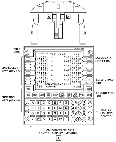
Control Display Unit
The Control Display Unit (CDU) supplies pilot interface to the FMS system. Each CDU is installed in the pedestal with four quick-release fasteners. At the rear, the CDU has a receptacle that supplies the interface with the other aircraft systems. At the front, the CDU has the controls that supply the primary interface between the flight crew and the flight management system.
The CDU communicates with the FMC and other subsystems using the ARINC 739 or ARINC 429 protocol. This supplies the capability for the CDU to act as a Multifunction Control Display Unit (MCDU) and communicate with other compatible subsystems, for example, FANS (optional), Datalink, or Satellite Communication (SATCOM). The available subsystems are selectable from the INDEX or MCDU MENU pages at all times.
The CDU controls the following functions:
- Start the FMS
- Control the communication and navigation radios
- Make and change the flight plans
- Monitor the FMS conditions
The CDUs receive electrical power as follows:
- CDU No. 1 receives 28 VDC power from the L ESS BUS through circuit breaker CB1-A4 on the left circuit breaker panel (CBP1)
- CDU No. 2 receives 28 VDC power from the R MAIN BUS through circuit breaker CB2-A4 on the right circuit breaker panel (CBP2)
The CDU front panel lighting is supplied by the integral lighting system.
CDU Controls
The CDU has the following controls:
Line Select Keys
The CDU has 12 line select keys (LSK) (6 line select keys on each side of the display). Each line select key (LSK) is related to a data field. The data fields include DATA1L to DATA6L on the left side of the CDU. The data fields also include DATA1R to DATA6R on the right side of the CDU. Pushing a line select key selects the FMS function in the data field. The functions in the data fields, and the operation of the line select keys, are related to the control/display page that shows on the display.
On some control/display pages, the bottom pair of line select keys can operate as control keys. On these control/display pages, a display line shows, that contains all dash symbols. This display line divides the display part of the CDU display from the control part of the display.
Function Keys
The CDU has 12 function keys in the area immediately below the CDU screen. The CDU also has two other function keys (IDX, TUN) in the left side of the alphanumeric keys area. The function accesses directly to CDU control/display pages.
The MSG key, when pushed, shows the MESSAGE page or accepts one system message.
The DIR key, when pushed, shows the active direct-to (ACT DIRECT-TO) page on the display.
The FPLN key, when pushed, shows the active (or first) flight plan (ACT FPLN ) pages on the display. These pages let the flight crew record, examine, or change the active flight plan.
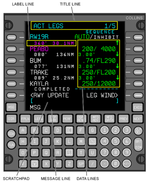
The LEGS key, when pushed, shows the active legs (ACT LEGS) page on the display.
This control/display page lets the flight crew record, examine, or change the different flight legs of the flight plan.
The DEP ARR key, when pushed, shows the departure/arrival index (DEP ARR INDEX) page on the display. This control/display page lets the flight crew make selections for the departure or the arrival parts of the flight plan.
The PERF key, when pushed, shows the performance menu (PERF MENU) pages on the display. These pages let the flight crew record a cruise altitude or set the transition altitude/flight level.
The DSPL MENU key, when pushed, shows the DISPLAY MENU page on the CDU. The DISPLAY MENU page shows a menu of the possible MFD text data pages and MFD/PFD map display pages.
The MFD ADV key, when pushed, shows the MFD DISPLAY ADVANCE page on the CDU. The MFD DISPLAY ADVANCE page shows a menu that lets the flight crew show a different text data page on the display.
This text data page can be the text data page that was shown immediately before this time. It also can be the subsequent text data page.
The MFD DATA key, if pushed again and again, shows a text data page on the MFD. It then shows the MFD display that was shown on the display immediately before this time. The text data page that shows is the display page that the flight crew last set from the display menu page.
The PREV key, when pushed, causes the previous control/display page to show on the display. This occurs when the CDU function has more than one control/display page.
The NEXT key, when pushed, causes the subsequent control/display page to show on the display. This occurs when the CDU function has more than one control/display page.
The EXEC key, when pushed, lets the flight crew put a changed flight plan into operation. EXEC shows on the CDU when a flight plan is changed. The flight crew must push the EXEC key to accept the changes and put the changed flight plan into operation.
The IDX (index) key, when pushed, shows the INDEX page. The INDEX page has a menu of functions that let the flight crew show system conditions, set initial position, and control sensors. The index key also controls the FMS, examines the data base, and downloads the data base.
The TUN key, when pushed, shows the radio TUNE page on the display. The TUNE page supplies control/display functions for the aircraft radios.
Alphanumeric keys
The alphanumeric keys are used for data entry. When pushed, the alphanumeric keys cause the related symbols to show on the scratchpad line.
The following are alphanumeric keys:
- 0-9 number keys
- A-Z letter keys
- Period symbol key
- ± (plus/minus) symbol key
- SP (space) key
- The / (slash) symbol key
- CLR/DEL (clear/delete) key
The N, S, E, and W keys allow the flight crew to enter geographical coordinates. The N and S keys enter a latitude coordinate. The E and W keys enter a longitude coordinate.
With data in the scratchpad, the CLR/DEL key operates like a backspace key. The CLR/DEL key, when pushed, erases the last alphanumeric symbol that was recorded in the scratchpad line.
If the CLR/DEL key is pushed and held, it erases all of the symbols in the scratchpad line. The CLR/DEL key also can erase a system message or can cancel a DELETE command.
The CLR/DEL key can also erase system data. When there is no data in the scratchpad and the DEL/CLR key is pushed, it causes DELETE to show on the empty scratchpad line.
Then, a line select key must be pushed to erase the data in the adjacent data field. Thus, the effect of the DELETE command is to erase data from the applicable data field. Some data fields cannot be erased. The DELETE command then erases the value in that data field, but causes its initial system value to show.
Lighting Control
The BRT/DIM (bright/dim) button, at the bottom right corner of the CDU front panel, adjusts the intensity of the display lighting.
CDU Displays
Title Line
The TITLE LINE shows the page title and the page number for the control/display page. The page number shows the number for the control/display page that shows on the display. A slash symbol follows the page number. Then, a number that gives the total number of control/display pages follows the slash symbol.
Label/Data Lines
There are 12 label/data lines on the CDU. These display lines are in pairs. The first display line in the pair is usually a label line, and the second display line in the pair is a data line. Each label line contains two label fields. One label field is on the left side of the label line, and one label field is on the right side of the label line. The label fields are LABEL 1L to LABEL 6L on the left side and LABEL 1R to LABEL 6R on the right side.
The label field identifies the data that shows immediately below it. The label field and the data field, on the left side of a label/data line pair, are related to a line select key. That line select key has a location that is immediately to the left of the data field. The label field and the data field, on the right side of a label/data line pair, are related to a line select key. That line select key has a location that is immediately to the right of the data field.
The data fields can show large or small alphanumeric symbols. When the system supplies the data, the alphanumeric symbols are small. When the flight crew supplies the data, the alphanumeric symbols are large. The data field can contain the name of a mode selection. When that mode is in operation, the alphanumeric symbols in the data field are large. When that mode is not in operation, the alphanumeric symbols in the data field are small.
Scratchpad Line
The scratchpad line shows data while it is recorded with the alphanumeric keys. If data shows in one of the data fields, and the related line select key is pushed, the data also shows on the scratchpad line. It is possible to change the data while it is on the scratchpad line, then move it back into a data field. Bracket symbols identify the scratchpad line. Data shows on this scratchpad line so that it can be visually examined and accepted before it is moved into a data field.
Annunciation Line
One annunciation line shows as the bottom display line on some control/display pages. This display line informs about conditions of operation.

02/01/16
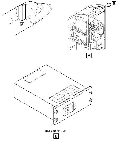
Data Base Unit
The data base unit (DBU) is in the left equipment rack with four quick-release fasteners. The unit has two receptacle that supplies the interface with the other aircraft systems.
The DBU is a data loader that uses universal serial bus (USB) memory drive to install data into the FMS. The installed data is navigation, performance or V-speeds databases used by the FMS. The DBU is also used to install way points and airport data. This data can only be installed when the aircraft is on the ground in a weight-on-wheels (WOW) condition. The DBU is used to write flight/pilot data to the USB memory device. The DBU also interfaces with the maintenance diagnostic computer (MDC) to download maintenance data to the USB memory device. The CDU controls the DBU modes of operation.
The database unit gets 28 VDC power from the R MAIN BUS through the circuit breaker CB3-D1 on the left secondary power center (LSPC).
02/01/16
System Operation
The CDU is the primary interface with the pilot:
- Function keys supply quick access to frequently used CDU pages.
- A full alphanumeric keypad allows pilot input.
- Multiple Line Select Key (LSK) buttons supply additional control of FMS functions.
Full color electronic flight displays (in addition to the CDU) supply additional FMS data and both map and text page capability.
To supply navigation, flight plan, map display, and steering functions, the flight management system:
- Makes and changes the flight plans
- Does lateral flight plan point-to-point navigation (using many navigation sensors)
- Does vertical navigation
- Calculates the flight parameters
- Sends the lateral/vertical steering command outputs to the flight control system
- Selects the navigation modes
- Tunes the navigation and communication receivers
- Selects the display formats that other flight compartment displays use
The FMS supplies these primary functions through different FMS operations modes. The FMS operation modes are related to the FMS configuration of the specific aircraft and also to the FMS optional functions that are included in the installation.
Key Operational Features
- System performance predictions are available for the Active Flight Plan (ACT FPLN), the Modified Flight Plan (MOD FPLN), and the Secondary Flight Plan (SEC FPLN).
- The takeoff and landing performance advisory function (Vspeeds) supplies an electronic table lookup and display of the airframe data for Vspeeds, weight limits, and runway length requirements.
- Navigation is based on using all the available aircraft navigation sensors to fly from waypoint to waypoint along a flight plan route. With the navigation and other sensor data available to it, the FMS determines the present position relative to the flight plan route and computes steering commands for use by the flight guidance system to fly the aircraft along the route. The FMS does not blend other navigation sensors when the GNSS sensor is operating in a SBAS mode (for example, SBAS LPV approach).
- Selectable Independent (INDEP) and Synchronized (SYNC) FMS modes of operation are provided for dual FMS installations. In the SYNC mode, certain initialization operations and selections performed on one FMC are communicated to the other FMC. This includes selection of active navigation database, de-selection of NAVAIDs, enabling/disabling of VOR and/or DME from the navigation solution, and performance mode selection values entered on the FUEL MGMT pages.
FMS Operation Modes
The FMS operation modes include all the flight plan and navigation modes (preflight initialization, flight planning, sensor navigation, lateral steering, and vertical navigation (VNAV) modes). These modes also include several control modes (display control, database load, and radio tune modes).
Preflight Initialization
Preflight initialization verifies the status of the FMS configuration and initializes the FMS and the long-range navigation sensors.
Typical FMS preflight procedures can include:
- Use the STATUS pages to make sure that the correct navigation, performance, and Vspeeds databases are installed in the FMS.
- Check/set the date and time on the STATUS 1/2 page. If dashes show, the date and time can be set.
- Check/set the initial position on the POS INIT 1/3 page.
- Make sure that VOR USAGE and DME USAGE is enabled (as required) on the VOR/DME CONTROL page and (if necessary) individually inhibit the use of VOR or DME NAVAIDs that Notice To Airman (NOTAM) messages show are out of service.
- Check that Synchronized (SYNC), not Independent (INDEP) mode of operation shows on the FMS CONTROL page.
- Check for proper operation of the GNSS sensors on the GNSS STATUS pages. Optional equipment and functions installed in an aircraft and operational variations may delete or add additional preflight functions for the FMS. Refer to the Aircraft Flight Manual (AFM) for specific FMS preflight procedures for the aircraft.
Flight Planning
The flight planning modes let the FMS system supply display/control functions for flight plan data. Flight plan data include airways, departure routes, arrival routes, approaches, and holding patterns. It also includes, direct flight legs, origin/destination airports, and pilot-specified waypoints.
The Active (ACT/MOD) Flight Plan (FPLN) generates steering commands for use by the aircraft flight guidance system while the Secondary (SEC) flight plan can be saved for later use. Creation of each type is identical except the page names are different. Typical departure procedures can include updating the FMS immediately prior to takeoff, setting the departure route that may include a departure procedure and transition, and joining the airway system for the en route phase of flight. The en route portion may use the HOLD function, Direct-To waypoint function, fly offset parallel course function, flyover waypoint option, and FIX INFO operations to arrive at the destination airport.
Sensor Navigation
The sensor-navigation operation mode lets the FMS supply navigation data in the en-route, terminal, and approach phases of the flight. The FMS can use combination of distance measuring equipment (DME), VHF omnidirectional range/DME (VOR/DME), dual VOR, dual DME, inertial reference system (IRS), and global positioning system (GPS). The navaid selection algorithm does the selection of the best navigation signal sources in the area and automatically tunes the aircraft receivers to them.
If the FMC cannot use position data from the sensors, it will continue to estimate the position by dead reckoning (DR), if dead reckoning data (heading and airspeed) are available. Also, the FMS has a nav-to-nav capture function that lets an ILS be set to help the pilot control the aircraft after an FMS flight plan ends. When the aircraft gets near the preselect navigation source, the FMS tunes the on-side localizer (LOC) receiver to the reference frequency and sets the LOC as the navigation source.
Lateral Steering
The FMS supplies the flight guidance computer (FGC) (through the IOCs) with smooth lateral steering for all phases of the flight plan as they become active. The FGC also receives control data from the flight guidance panel (FGP). Selection of the navigation and steering sources are shown on the PFD. To stop the FMS lateral steering function, select a different navigation source or cancel the navigation selection completely. The FGC lateral modes are described in the AFCS.
Vertical Navigation
The Vertical Navigation (VNAV) mode enables the FMS to supply (through the IOCs) commands for different FGS vertical modes, and references related to these modes. VNAV mode automatically commands the flight director to sequence modes and set target speeds and altitudes. This is to make sure that the flight plan requirements are followed within the constraints of the preselect altitude setting. Because of the integration of VNAV data with the autopilot, pilots have full command of the normal autopilot modes (Pitch, Flight Level Change, Vertical Speed, and Altitude Hold) while the VNAV mode is active. If the aircraft is commanded to violate a VNAV constraint, the VNAV functions give the pilot appropriate warning annunciations.
During the various phases of flight, VNAV follows the flight plan. It captures an altitude to level the aircraft at the flight plan altitude constraints, and begins descent at a planned location. Step climbs can be initiated with the altitude preselector and selection of the desired climb mode.
During descent, VNAV computes a geographical path to each waypoint with an altitude constraint, and provides guidance relative to that path. If there are multiple altitude constraints at various waypoints along the flight plan, the FMS automatically adjusts the descent path for a smooth stabilized descent while it makes sure that the altitude constraints are honored.
Display Control
Three function keys on the FMS CDU (MFD DATA, DSPL MENU, and MFD ADV keys) are used to control the map or text data displays that show on the MFD.
Database Control
The FMS controls the database load operation to get/update waypoints, airports, flight paths, and approach procedures. The FMS lets the flight crew select an active database and use the data to create/change flight plans and to supply navigation functions.
Radio Tune
The procedure to tune/control the transmitters and receivers of different radio sensor systems (RSS) is usually done through the display control panel (DCP), together with the use of the radio menus that show on the MFD. The RSS that are tuned and/or controlled through the MFD menus include the HF and VHF communication radios, the VHF navigation radios, the automatic direction finder (ADF), the ATC transponders, and the TCAS.
As a secondary procedure, the flight crew can also use the FMS CDU to tune/control the different radio equipments (selection of CDU or MFD tune procedure is done with the reversion select panel (RSP)). Access to the CDU radio-tune functions is possible with the use of the CDU TUN key. When pushed, this key shows a radio TUNE page. The TUNE page includes selections that give access to functions that can tune/control the RSS transmitters and receivers.
02/01/16
FMS Configuration
In the dual FMS configuration, the FMS can be set as default synchronized (SYNC), independent (INDEP), or pilot-controlled system. If the dual FMS operation is set to be pilot-controlled, the SYNC/INDEP mode selection is given on the CDU FMS CONTROL page.
Independent Mode
In the independent mode, the FMCs are not synchronized. No mode selections or flight plan data from one FMS is automatically given to the other FMS. But, the magnetic/true (MAG/TRUE) heading data is given to the other FMS. The MAG/TRUE heading display mode selection is coordinated in the independent mode. Personnel can move the active flight plan, route plan, pilot-defined waypoints, and route list between the two FMCs. When the flight plan is moved from the other FMC, all data about the moved flight plan is given by the other FMC.
In the independent mode, flight plans can be copied from one FMS to the other FMS. If a flight plan is copied during a change (MOD FPLN page shows), the flight plan is copied without the new data. If the flight plan is copied, and there is no flight plan on the other FMS to copy, the message NO XSIDE PLN shows on the CDU.
The database must be the same on each FMS to copy a flight plan from one FMS to the other. If the database is different on FMS when a flight plan is copied, the message CHK SELECTED DATA BASE shows on the CDU.
The independent mode is automatically started when an FMS fail condition is found. The fail condition can be a hardware fail condition, or a difference between each FMS in the navigation database or software version.
The independent mode has the following properties:
- All communication between the FMCs is discontinued
- Synchronization of cockpit management functions such as map data selection is canceled
- There is no synchronization or transfer selection of flight plan or route plan
- Each FMC sequences its version of the flight plan as in independent mode
- There is no navigational position monitor function of the other FMC
- Position is monitored with enabled sensors in all modes
In the independent mode, the navaid selection algorithm for the automatic radio tune operation is the same as in the synchronized mode. To keep duplication to a minimum and give maximum sensor usage, each FMC directly tunes the same-side navigation radios only.
Synchronized Mode
In the synchronized mode, the following functions are automatically synchronized between the two FMSs:
- FMS position initialization (optional)
- Database selection
- Disable selection for the navigation sensors, except for GPS and IRS
- All mode selections
- FIX information entries
- Flight plan entries or changes
- Second flight plan entries or changes
Also, the initialization and selections made on one of the two FMCs are given to the other FMC. This includes:
- Selection of active database
- Cancel selection for the navaids
- Selection of enable/disable the VOR/DME from the navigation solution
- Performance mode selection
- Fuel flow and ground speed value entries on the FUEL MGMT page
In the synchronized mode, changes to a flight plan on one FMS are entered through the CDU.
The flight plan changes are made to the active plans only after the EXEC function key on the CDU is pushed. When this key is pushed, the flight plan is synchronized immediately with the other FMS.
Only one FMS can change the active flight plan. If the two FMS try to change the active flight plan at the same time, the message XSIDE EDIT IN PROGESS shows on the CDU. The same message shows on the CDU, if the pilot/copilot tries to start a flight plan from the other FMS.
When the two FMSs are set as navigation sources, the FMS that is the active navigation source controls the sequence of the flight plan legs.
When one FMS is set as the navigation source, that FMS controls the sequence of the flight plan legs.
The magnetic/true (MAG/TRUE) heading display-mode selection is coordinated in the synchronized mode, as are thrust management entries and selections (if thrust data is loaded). The synchronized mode of operation has the properties that follow:
- After approval of the modified flight plan (set by the EXEC key), the active flight plan is moved to the non-control FMC (opposite-side FMC). This synchronization includes direct-to edits, all holding pattern data (expect-further-clearance (EFC), TIME, (knots indicated speed (KIAS), etc.) and all performance initialization data
- Changes to the route plan are immediately moved to the opposite-side route plan
- Crew entries on the FIX INFO page are immediately sent to the opposite-side FMC
- The FMC which is the navigation source on the side pointed to by the autopilot transfer (AP XFR) selection will control the flight plan leg sequence. If only one FMC is set as the navigation source, that FMC will control the flight plan leg sequence.
In certain power-up conditions, one FMC can find that the other FMC is more current. In such cases, one FMC can automatically have its data selections and flight plan updated from the opposite-side FMC.
FMS Optional Functions
In addition to the two equipment-configuration options (dual FMS), the FMS can include several operation-type options that supply other FMS functions. These functions are related to the specific equipment installed on each aircraft, and also to the operator requirements.
The optional FMS functions include in particular:
- The FMS V-speed options:
- Single FMS V-Speed
- Dual FMS V-Speed
- FMS takeoff and Landing Performance and Integrated V-Speeds
- RNP Approach
- RNP AR ≥ 0.3
- The FMS 3-D Nav Map.
The FMS V-speed options supply data entry and data display fields on the CDU for takeoff speeds, weight, and runway length data.
The integrated V-speeds function lets the flight crew do the selection of the calculated takeoff V-speed values as bugs for display on the PFD airspeed scale.
The RNP AR ≥ 0.3 option adds support for special aircraft and aircrew authorization required (SAR or AR) operations to 0.3 NM and greater on approach. RNP AR requires the FMS to be using GNSS for position estimation.
The 3-D NAV maps option lets the flight crew see on the MFD, in a 3-D format, the flight plan and predicted vertical trajectory of the aircraft. With the FMS graphical data, the flight crew has a better indication on the current and future aircraft situations.
The 3-D map display is referenced to true north and the way points are shown at their real latitude and longitude. The 3-D map display is controlled with the cursor control panel (CCP) joystick, and the SHLDR (shoulder) and SIDE view pushbuttons on the CCP.
02/01/16
Controls and Displays
Primary control of the FMS is through the Control Display Unit (CDU). The CDU acts as the single control point for FMS operations and functions. The Primary Flight Display (PFD) and the Multifunction Display (MFD) provide additional display capability for FMS information and functions.
The CDU is the primary pilot interface with the various functions of the FMS. It has a color display to show the FMS related information and function modes. The Line Select Key (LSK) buttons around the display are used to select modes and copy or transfer displayed information. The CDU function keys are used to directly select many of the FMS functions and display modes. The CDU also has a full alphanumeric keypad for data entry.
All operations that entail data entry for FMS operating functions are done through the use of a scratchpad entry system. Flight plan data, performance data, or data for other FMS operations is entered directly into the scratchpad with the keypad, or by pushing a LSK to copy data shown on a display line to the scratchpad. From the scratchpad, data is transferred to the appropriate data line by pushing the LSK for the entry position.
FMS operating modes are selected directly by pushing the appropriate function key, or by pushing a LSK adjacent to an item in a menu shown on the display (for example, from an INDEX menu page). Some functions are alternately switched on and off with sequential pushes of the associated LSK or a function key.
The PFD shows the information related to FMS operations, including Navigation (NAV) source annunciation, course/deviation bar, a navigation data readout, Vertical Navigation (VNAV) information, and FMS messages.
The MFD shows both FMS Map and Text displays. Map displays show the various navigation facilities in the flight plan, as well as progress along the flight plan route. A text window that shows navigation and VNAV information above the MFD map display can be enabled. Text displays show information on navigation and aircraft performance in text only formats.
The top line of the CDU display shows a title/mode, and the current page number and total number of pages as applicable for that display mode. Below the title/mode line, there are six data lines and six label lines to show data for a given display page. The two bottom lines on the display are used for the scratchpad and message lines. The scratchpad shows cyan brackets ([ ]). Many of the display pages are configured to show two columns of information, which allows the use of the Line Select Key (LSK) buttons on both sides of the display to select, copy, or transfer displayed data.
02/01/16
CDU Pages (Access from the INDEX Menu)
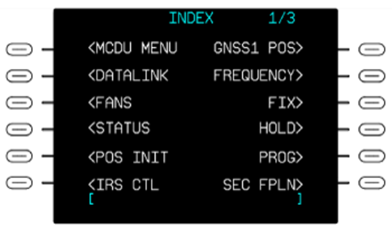
Pushing the IDX key on the CDU shows the INDEX page. The INDEX page has a top-level menu that gives access to different CDU pages.
The CDU INDEX pages supply the following primary flight planning functions:
- System status at power-up
- Position initialization
- Navigation systems enable/disable functions
- Control/display of flight planning data (waypoints, hold patterns, and navigation database functions; aircraft performance, vertical navigation, and fuel management parameters)
The primary CDU pages opened with the INDEX menu selections and the related data are described in the following sections.
INDEX Pages
The INDEX page that shows on the CDU is related to the number and type of sensors installed on the aircraft. Thus, this page is not the same on all aircraft. Given the configuration of some aircraft, the FMS can have two index pages. The INDEX menu pages are used to select available functions that are not directly selectable with the function keys. The INDEX pages can be considered the primary menu for the FMS. Some selections available on the INDEX pages include access to the system DEFAULTS pages, VOR/DME, GNSS, IRS, and FMS CONTROL pages, the HOLD function, the Secondary Flight Plan (SEC FPLN) function, the ROUTE MENU, and others.
The INDEX page 1/3 includes, on the left side area, the menu items that follow:
- MCDU MENU (multipurpose CDU menu)
- DATALINK
- FANS
- STATUS
- POS INIT (position initialization)
- IRS CTL (IRS control)
- FMS CTL (FMS control)
The INDEX page 1/3 includes, on the right side area, the menu items that follow:
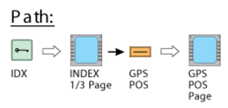
- GNSS1 POS (GPS position)
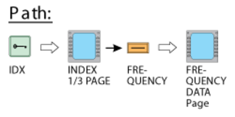
- FREQUENCY
- FIX
- HOLD
- PROG (progress)
- SEC FPLN (second flight plan)
Note:
On the INDEX page 1/3, the control functions that have FMS 1 in the label field are for the FMS No. 1. The control functions that have FMS 2 in the label field are for the FMS No. 2.
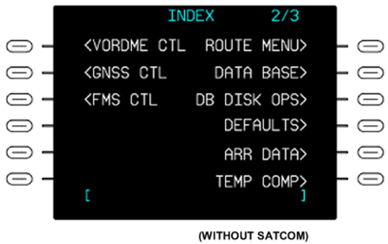
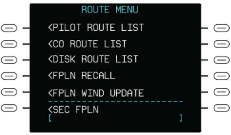
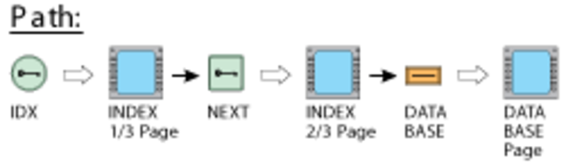
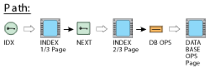
The NEXT key, when pushed, shows the INDEX page 2/3. This page includes the menu items that follow:
- VORDME CTL (VOR control)
- GNSS CTL (GPS control)
- FMS CTL (FMS control)
- ROUTE MENU
- DATA BASE
- DB OPS (data base disk-operations)
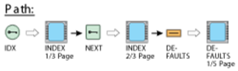
- DEFAULTS
- ARR DATA (arrival data)
- TEMP COMP
The NEXT key, when pushed, shows the INDEX page 3/3. This page includes the menu items that follow:
- LRN POS DATA.


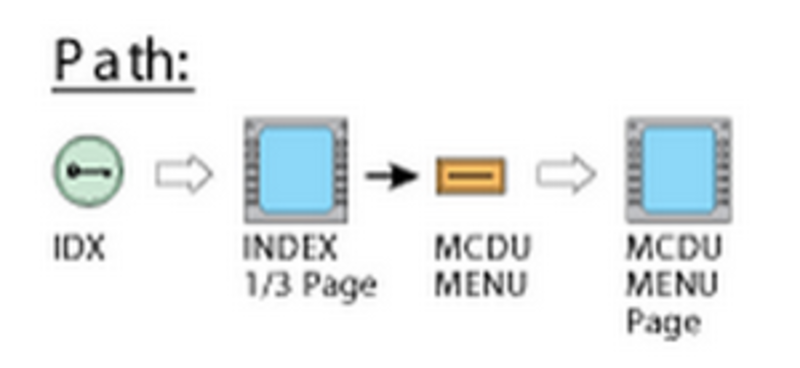
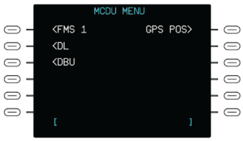
MCDU MENU
The MCDU MENU line select key (LSK) on the INDEX page, when pushed, shows the MCDU MENU page. The MCDU MENU page supplies access to FMS and other back-up display functions. This page shows when the FMS is not operating so that the pilot can have access to the non-FMS function (for example, DATALINK, SATCOM (optional), and GPS POS).
The MCDU MENU function lets the CDU operates as a multipurpose control display-unit (MCDU) and communicates with other ARINC 739 compatible subsystems (for example: Rockwell Collins airborne flight-information-service (AFIS)).
When the FMS 1 line select key is pushed, the CDU display returns to the FMS INDEX page. If the SATCOM line select key is pushed, the CDU will show the page data for the SATCOM system. If the DL line select key is pushed, the CDU will show the page data for the data link system. The optional SATCOM and DL legends are set with the configuration strapping unit (CSU).
When the DBU LSK is pushed, the DBU MENU page is shown. When the GPS POS LSK is pushed, the GNSS POSITION page is shown. This selection is only available when the FMS is not working.
If the MCDU selection is done but the MCDU system is not available, the CDU will show the message SYSTEM NOT AVAILABLE above the scratchpad line.
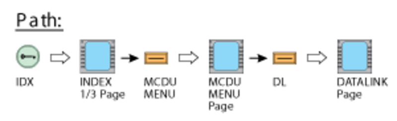
DATALINK Page
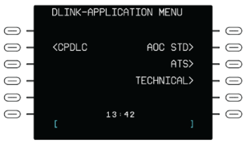
The DATALINK (DL) line select key on the INDEX page, when pushed, shows the DATALINK page. The DATALINK page shows the CPDLC function LSK and submenu datalink LSKs.
The DATALINK function is a non-FMS function. The DATALINK software uses the CDU as the interface, but the FMS does not control DATALINK.
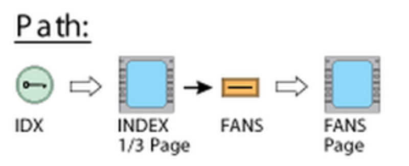
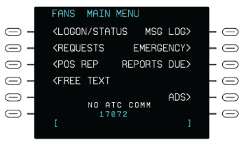
FANS Page
The FANS line select key on the INDEX page, when pushed, shows the FANS page. The FANS MAIN MENU page shows the initial LOGON/STATUS LSK and submenu LSKs.
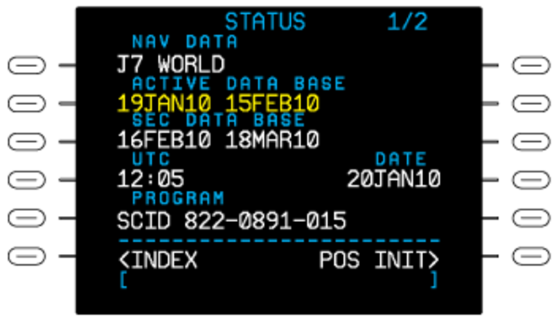
STATUS Page
Pushing the STATUS line select key on the INDEX page shows the STATUS page. The STATUS page is the first control/display page that shows after the system initially receives power. It gives the primary current configuration data. The STATUS 1/2 page shows the name of the active navigation database and the time period during which it is permitted to use the databases (i.e., the life of the databases). The secondary data base information is also shown. The time (universal time correlation/coordination [UTC]) and date are shown. The software configuration number for the FMC PROGRAM is also shown.
Note:
If a page other than the STATUS 1/2 page is displayed on initial power-up, push the IDX function key to show the INDEX 1/3 page, then push the STATUS LSK to show the STATUS 1/2 page.
In some situations, it is possible to use the line select keys to change the time and date displays. If the date is more than the time period permitted for the data, the display below the DATE label is yellow. If the first database or the second database is damaged, the data field shows dashed lines. If a database is not downloaded, the data field for that database is empty.
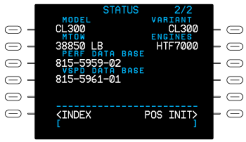
On the STATUS 2/2 page, check the PERF DATA BASE and VSPD DATA BASE numbers are present and are the same between each FMS installed. The MTOW, model, engine, and a/c variant information is also shown.
POS INIT Pages
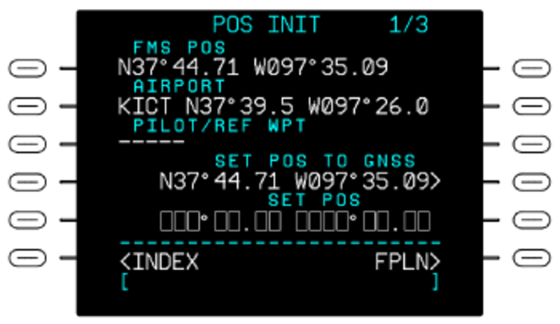
The POS INIT line select key on the INDEX page, when pushed, shows the first POS INIT page. The POS INIT pages let the flight crew set initial position data for the FMS computer and the long-range navigation sensors that are installed.
The first POS INIT page shows a data field that contains FMS position data. There is also a data field on which to record an airport ICAO (international civil aviation organization) identification. When the aircraft is on the ground, the AIRPORT data field can contain an airport ICAO identification. This identification is for the destination airport from the last flight, if such an identification was recorded.
An airport identification can be used for position initialization. First, the airport code (e.g. KLAX) is entered on the scratchpad line. Then, the AIRPORT line select key is pushed to move the code to the AIRPORT data field. The code shows on this field together with the airport latitude and longitude. The right second line select key is pushed to move the code and latitude/longitude data to the scratchpad line. The SET POS line select key is then pushed to move the code and latitude/longitude data to the SET POS field. To set the new initial position, the SET POS line select key is pushed, which causes the new position to show in the FMS POS data field. An entry into the SET POS data field sets the position value for the FMS computer, to the SET POS value.
The position values, for all applicable sensors, are also set to the SET POS value. The PILOT/REF WPT data field is used to record a way point identification. The flight crew can supply the way point identification or the identification can come from the navigation data base. When the aircraft is on the ground, the PILOT/REF WPT data field contains a way point identification. The data field contains this identification only if the flight crew sets the identification. The way point must be in 3 NM or less of the FMS position. If the PILOT/REF WPT data field contains a way point identification, the location of the way point shows to the right of the identification. It is possible to make a copy of this location on the scratchpad line and use it to set initial position. This identification and location data is erased at take off.
The second POS INIT page (2/3) shows FMS POS, GPS 1 POS, and GPS 2 POS data fields. Data in these fields give current position and ground speed (GS) from the FMC and the GPS.
The position data can be copied into the scratchpad for subsequent entry into the SET POS data field and can be used to set initial positions.
The entry of a navaid identifier that is in the data base will cause the same-side VOR radio to tune to the related navaid frequency. If a navaid station is received with valid VOR/DME conditions, its identifier will show in the NAVAID data field (dashes show below the NAVAID label when VOR/DME conditions are not valid). The UPDATE FROM NAVAID line select key, when pushed, shows the position data from the navaid, in the scratchpad. The first time, the position shows as a radial distance offset from the navaid. Then, through the use of the right bottom line select key, it is possible to show the data in altitude/longitude format. The calculated position is updated regularly with the use of the signals received from the specified navaid.
If the left bottom line select key is pushed while the navaid position data shows in scratchpad, it will cause the FMC position to be updated to the position reported by the navaid. The third additional POS INIT page (3/3) shows FMS POS, IRS 1 POS, and IRS 2 POS data fields. Other position data that is available from other sensors for use by the FMS is shown. Data in these fields give current position and ground speed (GS) from the FMC and the IRS.
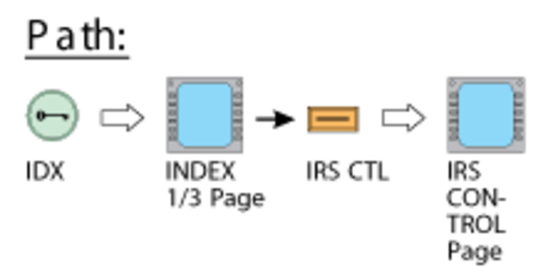
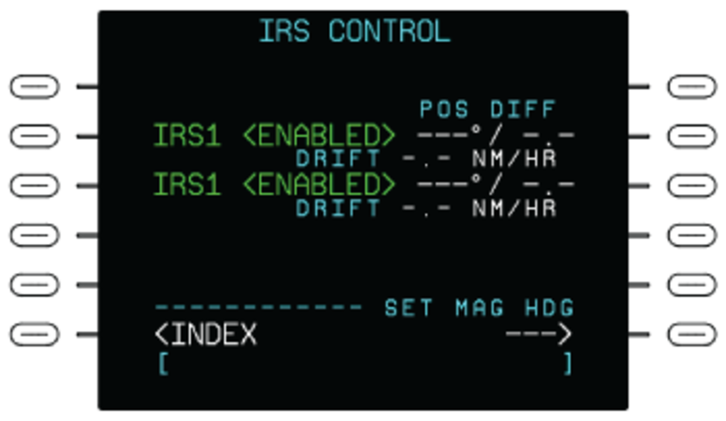
IRS CTL Page
The IRS CTL line select key on the INDEX page, when pushed, shows the IRS CONTROL page. The IRS CONTROL page shows the IRS1 and IRS2 ENABLED or DISABLED. It gives the primary current IRS sensor data. The IRS CONTROL page shows the position difference (POS DIFF) between the position of each IRS sensor and the position calculated by the FMS. Both direction and distance (up to 99.9 NM) are given for a POS DIFF, as well as drift rate if the IRS is set to NAV mode.
Dashes show for the POS DIFF and DRIFT if insufficient data is available for their determination. Dashes also show for DRIFT if IRS is NOT set to the NAV mode or for 30 minutes after an initialization.
VOR CONTROL Page
The FMS1 VOR CTL line select key on the INDEX page, when pushed, shows the FMS VOR CONTROL page. The FMS VOR CONTROL page lets the flight crew remove navaid stations data from the position estimation calculations.
The flight crew can set the system to ignore output from as many as 8 navaid stations. The system then does not use data from these stations when it calculates an estimate of the position. To ignore the output of a navaid station, the flight crew must record the navaid identification on the scratchpad line. Then the flight crew must push one or the other NAVAID INHIBIT line select keys to move the identification to the related data field. The system is set to use, or to not use, all of the VOR and DME data when it calculates system values. To do this, the flight crew can push the line select key related to the VOR AND DME USAGE data field. This causes the system to not use all VOR and DME data. The flight crew can then push the line select key again to let the system use all VOR and DME data.
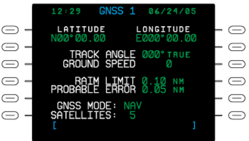
GPS POS Page
The GPS page is used to show the current GNSS position and related GNSS information. The information on the GPS page is for display only and cannot be edited. The GPS page shows:
- The current time and date.
- Latitude and longitude coordinates of the GNSS position.
- Track angle and ground speed.
- RAIM LIMIT in nautical miles.
- PROBABLE ERROR in nautical miles.
- The current GNSS MODE.
- The number of satellites the GNSS is currently tracking.
FREQUENCY Page
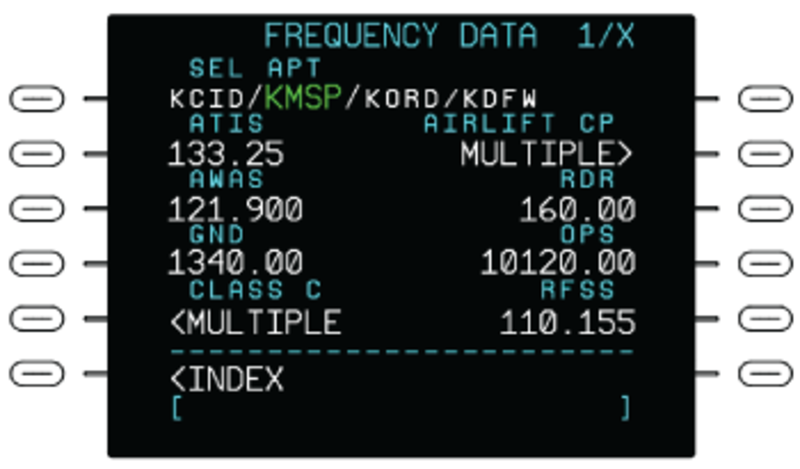
The FREQUENCY line select key on the INDEX page, when pushed, shows the FREQUENCY page. The FREQUENCY page shows communication frequencies associated with airports. The FREQUENCY page lets the flight crew set the frequencies to origins, destinations, and alternate airports.
If a pilot entered airport identifier is associated with more than one airport stored in the navigation database, the SELECT APT page shows that lists the identifier, ICAO country code, and the latitude and longitude for each airport. If there are no frequencies stored in the database, the FREQUENCY DATA page with the message NO DATA AVAILABLE page shows.
The FREQUENCY DATA page shows up to eight communication types per page, four on each side of the page. The types include Class B and Class C airspace frequencies. If more than eight frequencies are available for an airport, up to nine pages are available to show the frequencies. Push the PREV and NEXT function keys to show any additional pages. Communication types with more than one frequency available for a particular airport will display a LSK labeled MULTIPLE. Selection of MULTIPLE shows the communication type page for the selected airport.
VOR/DME NAVAID INHIBIT Page
When a specified VOR is known to be invalid, it can be inhibited to keep it out of the FMS position solution. Additionally, all VOR/DME and/or DME/DME sensor data can be disabled for use by the FMS when it determines the position.
The FMS VOR/DME CONTROL page is used to inhibit up to eight individual NAVAID stations. This page is also used to separately enable or disable VOR/DME USE and/or DME/DME USE by the FMS when it calculates the position solution.

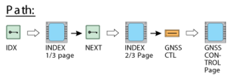
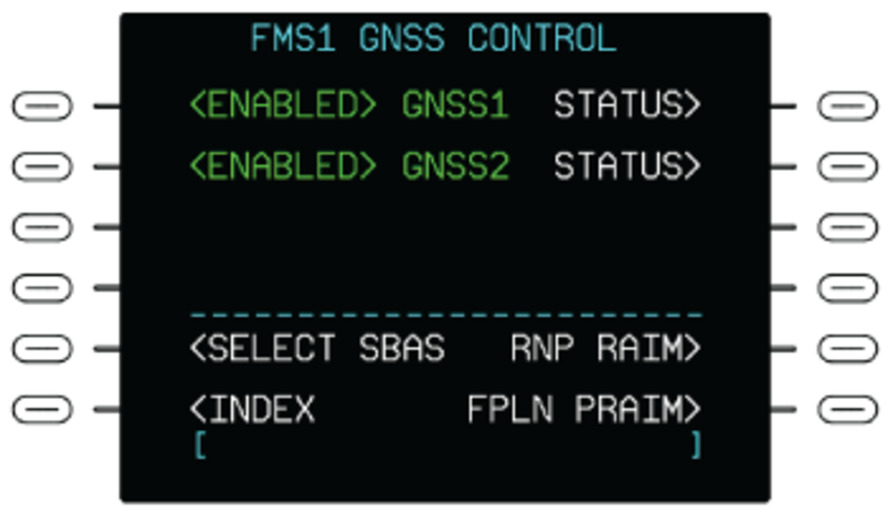
FMS GNSS CONTROL Page
The GPS CTL line select key on the INDEX page, when pushed, shows the FMS GPS CONTROL page. The GPS CONTROL page is used to do the selection of a GPS sensor for position data, or to cancel use of a GPS data.
When the system is permitted to use GPS position data, the ENABLED indication shows on this page, adjacent to one of the GPS names. When the system is not permitted to use GPS position data, the DISABLED indication shows adjacent to that GPS name. If the indication is DISABLED and the line select key related to that GPS name is pushed, the indication becomes ENABLED. If the indication is ENABLED and the line select key related to that GPS name is pushed, the indication becomes DISABLED.
The GPS CONTROL page shows the position difference (POS DIFF) between each GPS sensor position and the FMC calculated position. The POS DIFF data shows as dashes if data available to find the position difference is not sufficient.
The SAT DESELECT line select key lets the flight crew remove manually a satellite from the RAIM (receiver autonomous integrity monitoring) calculations. The applicable satellite number is entered in the data field below the SAT DESELECT legend, and then the SAT DESELECT line select key is pushed. The flight plan supplies the destination way point (below the DEST label) and the related ETA data. The APPR RAIM UNAVAIL message tells the flight crew that the GPS approach RAIM is not available.
The SELECT SBAS LSK shows the satellite bases augmentation system (SBAS) service provider selection page. The SBAS service providers can be enabled or disabled.
The RNP RAIM LSK shows the RNP RAIM page. This page is used to predict if RAIM is available for a non-precision approach and to de-select satellites that are unusable by NOTAM. SBAS approaches have RAIM built into integrity.
The FPLN PRAIM LSK shows the FPLN PRAIM page. This page is used to determine if RAIM is available for the route of the flight. This is used when SBAS availability is in question. If SBAS is available for the intended route of the flight, then the PRAIM is not required.
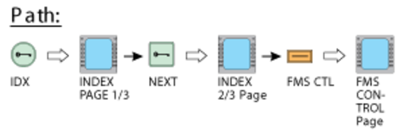
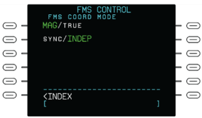
FMS CONTROL Page
Pushing the FMS CTL line select key on the INDEX page shows the FMS CONTROL page. The FMS CONTROL page lets the flight crew set the FMS to operate in the independent or synchronized mode. The flight crew can push the FMS COORD (coordination) MODE line select key to set the INDEP mode or the SYNC mode of operation. The FMS COORD MODE can be changed from INDEP to SYNC any time that the flight plan edit is not in operation. When an active flight plan and route plan synchronized source is set, the system starts the SYNC mode. If there is an exit from the page and no selection was made, the system goes back to INDEP mode.
In INDEP mode, the two FMS systems operate independently. Each system keeps different flight plans, initial values, and selection data. The data does not automatically move between systems.
In SYNC mode, the two FMS systems automatically use the same data. This gives synchronized control of the flight plans and the data for the initial values and selections.
When a flight plan is changed and put into operation, the system automatically makes a copy of the flight plan. The flight plan copy is then given to the opposite-side FMS. The types of data that the system automatically gives to the other FMS are the initial position values and the selection for the database. Also given are the selections for the data sources (navaid/sensor) that the system is not permitted to use at this time.
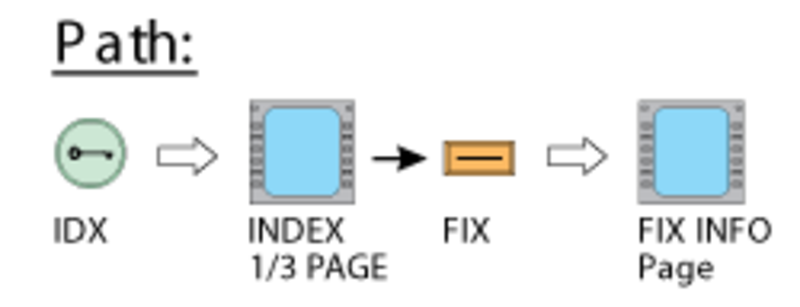
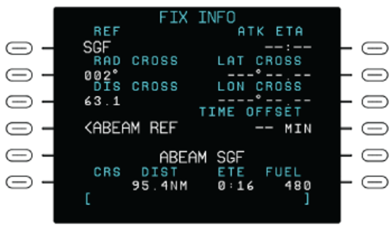
FIX INFO Page
Pushing the FIX line select key on the INDEX page shows the FIX INFO page. The FIX INFO page makes a pilot-specified waypoint at a point that is along the flight.
Note:
The FIX INFO page data on the two FMCs are not related. The effect of minor position differences can be seen as non-synchronized flight plan sequencing. Some startup data and selections are not synchronized between the FMCs. Personnel must enter this data first into one FMC and then into the other FMC.
The pilot-specified way point is related to some other way point as follows:
- The pilot-specified way point is on a bearing from the other way point
- The pilot-specified way point is some distance from the other way point
- The location of the pilot-specified way point is at right angles to the other way point
- The other way point cannot be a pilot-specified way point. It must be a way point on the flight plan (flight-plan way point)
To create a pilot-defined way point with the FIX INFO page, the flight crew must first record into the scratchpad line, one of the possible entries that follow:
- Reference (REF) way point identification
- Latitude crossing (LAT CROSS) data
- Longitude (LONG CROSS) data
The flight crew must then push the applicable REF, LAT CROSS, or LONG CROSS line select key to move the recorded data to the related data field.
The data fields below the DIRECT TO legend will show the CRS (course), distance (DIST), ETE (estimate time en route), and FUEL data in relation to the REF way point. Also, the REF way point will show on the MFD map as a way point that has a circle around it.
To make a pilot-defined way point, the FMS must have one of the three values that follow:
- A bearing from the REF way point
- A distance from the REF way point
- A location that is at right angles to the REF way point
To record a bearing from the REF way point, the flight crew must first record the bearing data into the scratchpad line. Then, the flight crew must push the RAD CROSS line select key. This will cause the FMS to calculate and show DIST, ETE, and FUEL values that are for the (first) intersection of the bearing radial line and the track line of the flight plan. Also, the MFD map will show the intersection and the bearing radial line form the REF way point.
To record a distance from the REF way point, the flight crew must first record the distance data into the scratchpad line. Then, the flight crew must push the DIST CROSS line select key. This will cause the FMS to calculate and show DIST, ETE, and FUEL values that are for the nearest intersection of the distance circle and the flight-plan track line. Also, the MFD map will show the intersection and a distance circle around the REF way point.
To record a location that is at right angles to the REF way point, the flight crew must push the ABEAM REF line select key. This will cause the FMS to calculate and show DIST, ETE, and FUEL values that are for the (first) point that is along the track line and at right angles to the flight plan track line. Also, the MFD map will show the intersection and the radial line from the REF way point.
If a FIX way point cannot be calculated from the recorded data, a NO INTERSECTION message shows on the scratchpad line.
A calculated FIX way point or data on the INFO page can be erased with the use of the CLR/DEL key on the CDU. The flight crew must first push the CLR/DEL key to record DELETE into the scratchpad. Then, the flight crew must push the applicable line select key to erase the data. The erase functions of the line select key are different:
- The use of the RAD CROSS line select key or DIS CROSS line select key, will erase almost all of the FIX way point data (the REF way point and the CRS/DIST data are not erased)
- The use of the REF, LAT CROSS, or LON CROSS line select key will erase all of the data from the FIX INFO page
ACT FPLN HOLD Page
Holding patterns can be defined for a flight plan by loading the holding patterns as part of SID, STAR, or approach procedures. Also, holding patterns can be added to a flight plan and holding parameters can be edited with the use of CDU pages that are opened with the HOLD line select key on the INDEX page.
Pushing the HOLD line select key shows one of the following pages:
- ACT LEGS page, if the flight plan contains no holding patterns
- ACT FPLN HOLD page, if the flight plan contains one holding pattern (that is not the missed approach or alternative flight plan)
- ACT HOLD LIST page, if the flight plan contains more than one holding pattern (or at least one that is the missed approach or alternative flight plan)
The ACT HOLD LIST, ACT LEGS, and ACT FPLN HOLD pages are similar. They can be used to record holding pattern parameters or to add a new holding pattern. The ACT FPLN HOLD page is described as an example.
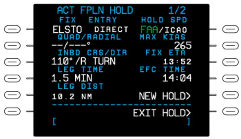
On the ACT FPLN HOLD page, the hold FIX and ENTRY identifications show on the top data line of the ACT FPLN HOLD page. The QUAD/RADIAL data field show entered/calculated quadrant and radial reference data that sets the holding pattern position in relation to the hold way point.
The inbound course/direction for the hold shows below the INBD CRS/DIR legend. To record a new course/turn direction, the flight crew must first enter the data into the scratchpad line. The applicable left line select key is then pushed to move the new course/turn direction from the scratchpad line to the INBD CRS/DIR data field.
Correct display patterns for the INBD CRS/DIR data are DDD, DDD/L, or DDD/R, where DDD is degrees and /L or /R shows a left or right turn pattern. If no turn direction is given, the turn is to the right.
Holding speed (HOLD SPD) (strapped for FAA or ICAO speeds), MAX KIAS, and LEG TIME values show on the display. These values are related to the altitude. It is possible to change one or the other of the two values.
The length of the inbound flight leg can be set with a LEG TIME or LEG DIST entry. When one or the other LEG parameter is recorded, the data field for the other parameter contains dash symbols.
If a hold is in operation, the FIX ETA data field shows the ETA to the hold fix. This time is calculated again at each cycle of the holding pattern. The EFC time (EFC TIME) is recorded on this control/display page. The display pattern is HH.MM, where H is hours and M is minutes.
When a hold is in operation, the ACT FPLN HOLD page shows an EXIT HOLD in the label field related to the lower-right line select key. If the EXIT HOLD line select key is pushed, this label will change to EXIT ARMED. Then, the EXEC key must be pushed to accept an exit from the holding pattern. The FMS then moves the aircraft to the hold fix.
After it moves through the hold fix, the FMS moves to the subsequent flight leg in the flight plan. The aircraft is moved immediately out of a holding pattern, if the flight crew uses a direct-to change.
The NEW HOLD line select key is used to enter a new holding pattern. If pushed, this key will give access to the ACT LEGS. The ACT LEGS page will have a HOLD AT display that tells the flight crew to supply the necessary input data to define the hold fix.
With the HOLD AT function on the ACT LEGS page, the flight crew can set the positions that follow as the hold fix:
- Present position (PPOS)
- A flight plan way point
- An off-plan way point
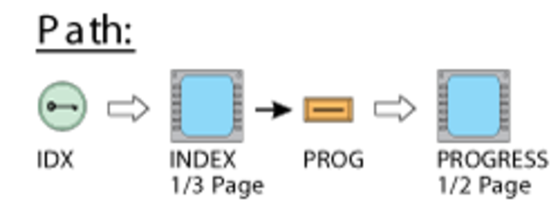
PROGRESS Pages
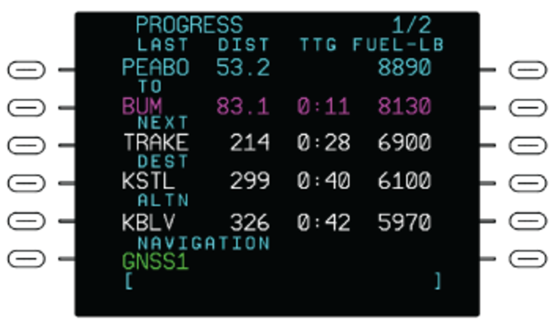
The PROG line select key on the INDEX page, when pushed, shows the PROGRESS page. The PROGRESS 1/2 page shows flight plan and performance data. In the PREDICTED performance mode, the performance data is based on the performance database for the aircraft and the planned speed schedule. In the MEASURED performance mode, the data is based on the measured fuel flow and ground speed. The page title changes to MEASURED PROGRESS when the MEASURED mode on the FUEL MGMT 1/3 page is selected. In the MANUAL performance mode, the data is based on the pilot entered fuel flow and/or ground speed on the FUEL MGMT 1/3 page. The page title changes to MANUAL PROGRESS when the MANUAL mode on the FUEL MGMT 1/3 page is selected.
The LAST waypoint is the last waypoint passed in the flight plan. Distance (DIST) shown for the last waypoint is the distance from that waypoint. FUEL-LB is the fuel remaining at that waypoint. The TO waypoint is the active waypoint.
Dashes show for the TO waypoint if there is no active waypoint due to a discontinuity, or after passing the last waypoint at the end of the flight plan. DIST is distance from the current position of the aircraft around the holding pattern to the fix. Time To Go (TTG) is the estimated time it will take to get to the TO waypoint. FUEL-LB is the current remaining fuel.
The NEXT waypoint is the waypoint following the TO waypoint in the flight plan, except when the TO waypoint is a holding fix. If the leg following the TO waypoint is a hold, the NEXT waypoint is the waypoint that follows the holding fix. DIST for the NEXT waypoint is the distance from the current position of the aircraft to the NEXT waypoint. TTG for the NEXT waypoint is the estimated time en route to the NEXT waypoint. FUEL-LB is the projected remaining fuel upon reaching the NEXT waypoint.
The DEST waypoint is the same as the DEST airport on the ACT FPLN page. If no destination airport is entered, dashes show for the DEST waypoint. DIST, TTG, and FUEL-LB are projected for the DEST airport, or runway threshold if an arrival runway has been selected, and are calculated from the current position of the aircraft along the flight plan route.
The ALTN waypoint is the same as the ALTN airport of the ACT FPLN page. If no alternate is entered, then dashes show for the ALTN. DIST, TTG, and FUEL-LB are projected for the ALTN airport and are calculated from the current position of the aircraft to the ALTN airport.
The navigation sensors used by the FMS are annunciated under the NAVIGATION title. The annunciations are based on the equipment installed in the aircraft. The list that follows shows the possible annunciations:
- DME/DME – (indicates two or more DME are being used).
- VOR/DME1 – (indicates that DME/DME is not being used and that the VOR and DME on side one are being used).
- VOR/DME2 – (indicates that DME/DME is not being used and that the VOR and DME on side two are being used).
- GNSS1 – (GNSS shows as the only sensor when being used for positional information and does not blend other sensors). This is the default when the GNSS is available with SBAS information.
- GNSS2–(same as GNSS1).
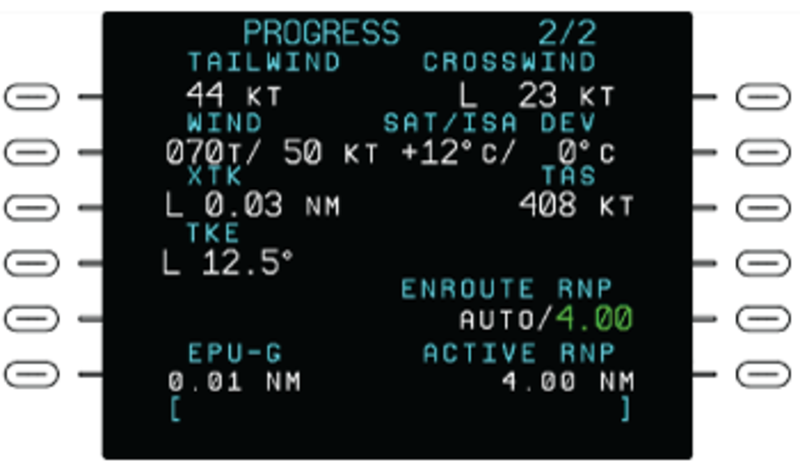
The PROGRESS 2/2 page shows the wind and temperature effects on the aircraft. The data is based on the measured fuel flow and ground speed. In the MANUAL performance mode, the data is based on the pilot-entered fuel flow and/or ground speed on the FUEL MGMT page. The page title changes to MANUAL PROGRESS when the MANUAL mode on the FUEL MGMT page is active. The PROGRESS 2/2 page shows:
- HEADWIND or TAILWIND and CROSSWIND components.
- WIND direction and speed. The related L or R label shows a left or a right wind direction. If wind speed is less than 5 kts, the wind speed display is zero and the L/R wind direction display contains no data.
- Static Air Temperature (SAT) and ISA temperature Deviation (DEV).
- Cross Track (XTK) direction and distance in nautical miles. The display includes an L or R label. This label shows that the aircraft is left or right of the flight plan track line.
- True Airspeed (TAS).
- Track Angle Error (TKE).
- EPU-G – Estimated position uncertainty (NM) and the Navigation mode indicator. Navigation modes: G – GNSS, I – IRS only, R – DME/DME or VOR/DME, or DR – Dead Reckoning (no navigation sensor updating the FMS).
- ENROUTE RNP – AUTO or 4.00 selections available. AUTO mode selects the RNP from the flight plan legs or phase of flight when outside the terminal area. Push the LSK to change mode.
- ACTIVE RNP – Computed value for display only. The RPN is entered by the pilot or calculated by the FMS. The POS ACCURACY is an indication for the FMS position error in relation to the RNP. If the expected position error is greater than the RNP value, the message LOW POS ACCURACY shows on the CDU.
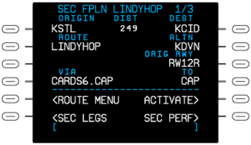
SEC FPLN Page
The SEC FPLN pages show the same type of information as the ACT FPLN pages. Also, in dual FMS installations, the SEC FPLN page with the last waypoint or route entry shows a LSK for SEC TRANSFER FROM XSIDE, which is used to transfer the secondary flight plan from the cross-side FMS. Like the active/modified flight plan, the secondary flight plan is complete when it includes both the lateral and vertical segments, plus the expected flight conditions required for time and fuel calculations. Unlike the ACT/MOD FPLN, the SEC FPLN does not use sensor data to estimate time, fuel, and weight calculations (estimates are based on the performance database of the aircraft). Manual changes affect the secondary flight plan performance calculations.
The second flight plan can include:
- Airways
- Standard instrument departures (SIDs)
- Standard terminal arrival routes (STARs)
- Approaches
- Holding patterns
- Direct flight legs
- Origin airport and destination airport
- Pilot-specified way points
The first data line contains the ORIGIN and DEST (destination) airports and the flight plan DIST (distance) between the two. The second data line contains the ROUTE name and the ALTN (alternative) destination selection.
The ORIGIN, DEST, and ALTN data fields let the pilot/copilot record the origin airport, destination airport, and alternative airport (KCID/KDEN for example). This lets the system show specified runway data that can be changed and made a part of the flight plan.
The ROUTE data field lets the pilot/copilot record a company route. The route can contain an origin airport, destination airport, arrival/departure runways, and flight legs that connect.
The pilot/copilot records ROUTE, ORIGIN, DEST, or ALTN data on the scratchpad line. Then, a line select key is pushed to move the data to the applicable data field. Flight plans are flight legs that go directly between way points or runways (direct legs).
Each entry below the VIA label field shows a direct flight leg. The direct flight leg has an end at the way point shown in the related TO data field.
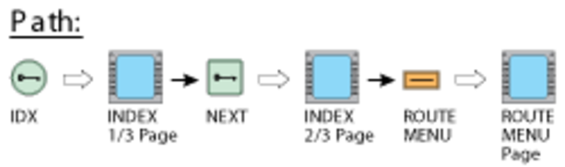
ROUTE MENU Page
The ROUTE MENU line select key on the INDEX page, when pushed, shows the ROUTE MENU page. The ROUTE MENU page gives access to the PILOT ROUTE LIST or to the DISK ROUTE LIST.
The PILOT ROUTE LIST line select key, when pushed, shows the PILOT ROUTE LIST page. All route names in the PILOT ROUTE LIST show in an alphabetical sequence, and have a colon symbol between the origin and destination. On the PILOT ROUTE LIST page, the pilot/copilot pushes the line select key adjacent to a name to download that route. If the selection of a route for download is done, the FMS will automatically show the SEC FPLN page that will includes the new route data.
The DISK ROUTE LIST line select key is used to read the flight plans that are on a diskette/USB memory drive that is put in the DBU. When this key is pushed, the DISK ROUTE LIST page shows. If there is no diskette/USB memory drive in the DBU, the message NO LOADABLE FILES shows in place of the flight plan list. If the USB memory drive does not contain any flight plans, the message NO LOADABLE FILES shows on line 6 in place of the flight plan list. The operator can change the USB memory drive in the DBU and push the READ DISK line select key to examine another USB memory drive.
The ACT STORE and SEC STORE line select keys are used to keep in memory route data for active flight plan and second flight plan respectively.
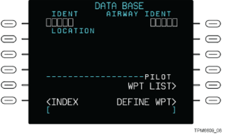
DATA BASE Page
Pushing the DATA BASE line select key on the INDEX page shows the DATA BASE page. The DATA BASE page shows the data kept in the navigation database and also defines pilot waypoints. When the DATA BASE page first shows, the line below the IDENT label contains dashes. To show specific data, the operator must enter an applicable identification code in the scratchpad line. Pushing the IDENT line select key moves the identification code to the IDENT data field line and < shows the related data stored in the database.
The identification entry can be that of:
- Pilot waypoint
- Enroute waypoint
- Nondirectional beacon
- Navaid
- Airport
An identification entry shows the following applicable data:
- Location and ICAO country code
- Navaid data (navigation system type, frequency, and magnetic variation)
- Airport data (runway data, elevation, and magnetic variation)
The DATA BASE page illustration shows, as an example, a pilot waypoint entry. The data for the applicable pilot waypoint includes:
- Identification (INDENT) data and the type of entry (PILOT WPT)
- LOCATION data for the pilot waypoint
- Magnetic (MAG) variation data
- Place bearing/distance (PLACE BRG/DIST) data
The DATA BASE page has a WPT LIST line select key which, when pushed, shows the PILOT WPT LIST page.
The PILOT WPT LIST page shows the pilot-specified way points that are saved in the data base. The line select key near a way point identification, when pushed, lets the flight crew do the selection of that way point. Also, the flight crew can do the selection of a pilot way point from the opposite-side FMS with the use of the TRANSFER FROM XSIDE line select key.
The DATA BASE page has as DEFINE WPT line select key which, when pushed, shows the DEFINE PILOT WPT page. This display/control page is used to define pilot way points. When the DEFINE PILOT WPT page first shows, the IDENT data field and the way point position data fields contain dash symbols. The flight crew can make an entry of a way point identification or a position in the scratchpad line and then push the IDENT line select key to show the applicable way point data.
The pilot way point parameters on the DEFINE PILOT WPT page, show in terms of position (LATITUDE/LONGITUDE), bearing/bearing data (PLACE BRG/PLACE BRG) or bearing/distance data (PLACE BRG/DISTANCE). The data can be entered/changed with new entries in the scratchpad line and the use of the line select key adjacent to the applicable parameter. A new way point specification is not saved until the pilot pushes the STORE WPT line select key.
DATA BASE OPS Page
The DB OPS line select key on the INDEX page (2/3), when pushed, shows the DATA BASE OPS page. The DATA BASE OPS page is used to load the FMS databases, or to copy routes and waypoints to a storage device. The data is uploaded from the universal serial bus (USB) memory drive into the FMC system memory.
The FMC can keep a first navigation data base (the data base in operation) and a second navigation data base. The route data base and pilot-specified way point data base can be downloaded to a USB memory drive from the FMS. Data is downloaded first to one FMC and then to the other.
Note:
A database load or write routes or waypoints operation can be done only when the aircraft is on the ground.
The navigation data base contains way point data on VORs, DMEs, en route intersections, non-directional beacons, and airports (this includes airport reference points, airport runway thresholds, and airport terminal way points). The contents of the data bases are adjusted to contain what is necessary to the flight crew.
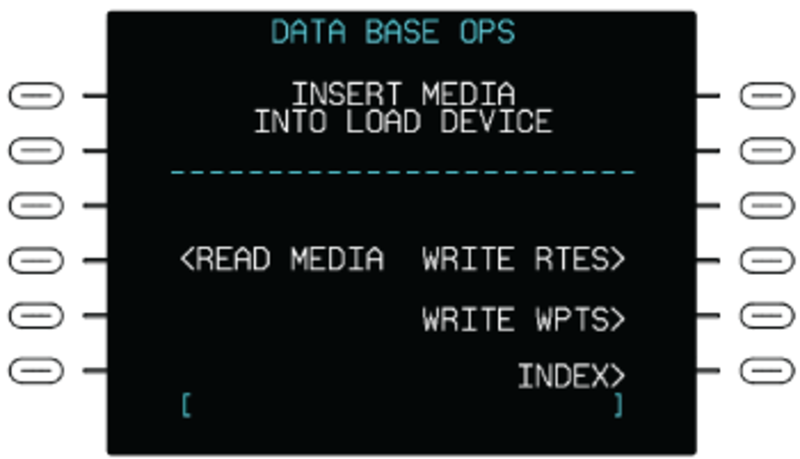
When the DB OPS line select key is pushed, the CDU first shows a control/display page that has an INSERT MEDIA INTO LOAD DEVICE message. The message tells the pilot/copilot to put a data base USB memory drive into the DBU. Load the storage device into the DBU, wait until the LED is green, then push the appropriate LSK on the page. Once the read or write function is selected, the CDU function keys will not operate until the load is complete or the process is canceled. If a navigation data base is found, a control/display page shows on the CDU to let the operator make a selection of the data (NAV, PERF, VSPD) to load into the system.
READ MEDIA
Used in loading a database into the FMS. The CDU shows various status pages while a database is loading. When a database has finished loading, the display indicates that the load is complete, then shows the STATUS page.
WRITE RTES
Used to copy routes in the database to the storage device in the DBU.
WRITE WPTS
Used to copy waypoints in the PILOT WPT LIST to the storage device in the DBU.
INDEX
Selection shows the INDEX 1/3 page.
After the data base is downloaded, a COMPLETE message will show for 5 sec. Then, the STATUS page will automatically show. This control/display page shows the period for which it is permitted to use the data base.
If a data base read operation is not successful, an error message will show on the CDU annunciation line and/or the MESSAGES page. The error messages include the messages that follow:
| MESSAGES | DESCRIPTION |
|---|---|
| NO NAV DATA BASE | The data base is not fully downloaded. Remaining data base is erased |
| NO LOADABLE FILES (white) |
Shows when the devices in the DBU does not contain any loadable files |
| DISK ERROR (white) |
A read error is found. Try again from INDEX page |
| DBU NOT RESPONDING (white) |
Shows when the DBU is not responding to commands from the FMS |
| DISK DRIVE NOT READY (white) |
Shows when no storage device is inserted in the DBU |
| FILE NOT FOUND (white) |
The files found by the DBU are not a data base file |
| LOAD DEVICE COLD | The DBU is too cold for operation |
| UNABLE TO READ USB (white) |
Shows when an action requires reading a database on the USB memory stick or the media is not recognized |
| USB REMOVED (white) |
The USB memory stick was remove while the FMS was accessing it |
| OTHER LRU USING DBU | The DBU is in use by another LRU |
| FMC FAULT | The data base cannot be saved. The FMC found a fault |
DEFAULTS Pages
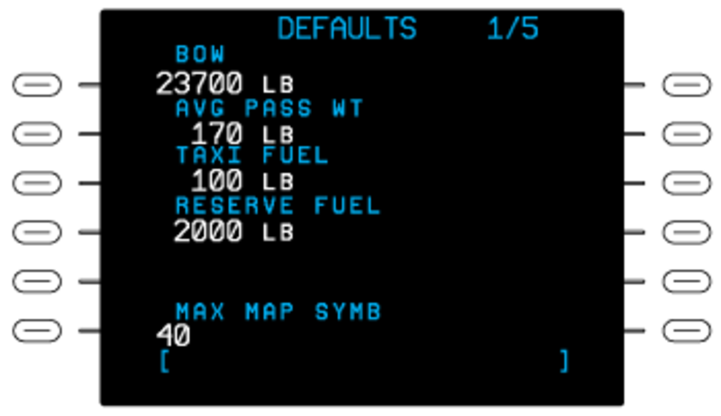
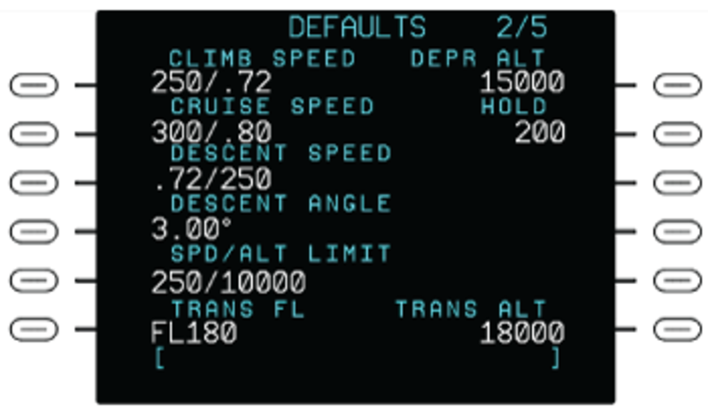
Pushing the DEFAULTS line select key on the INDEX page shows the DEFAULTS page. The DEFAULTS page sets the initial values for many performance, vertical navigation, and V-speed related quantities. When a new flight plan is downloaded, the initial system values are automatically downloaded. However, these values can be changed on a flight while not changing the initial system values for a subsequent flight.
The initial system values can be set for the items that follow:
- Basic operating weight (BOW)
- Average passenger weight (AVG PASS WT)
- TAXI FUEL weight
- RESERVE FUEL weight
- MAX MAP SYMB (maximum map symbols)
- CLIMB SPEED targets (IAS/Mach)
- CRUISE SPEED targets (IAS/Mach)
- DESCENT SPEED targets (IAS/Mach)
- DESCENT ANGLE
- Speed/altitude limit (SPD/ALT LIMIT)
- TRANS FL – Transition Flight Level (TRANS FL) is the flight level that the pilot sets the barometric altimeter to a local setting. The TRANS FL and TRANS ALT are separate altitudes
- DEPR ALT – Depressurization Altitude (DEPR ALT)
- HOLD – Shows the holding airspeed
- TRANS ALT – Transition Altitude (TRANS ALT) is the altitude that the pilot changes the barometric altimeter to a standard setting. Above this altitude all altitudes are expressed as a Flight Level (FL).
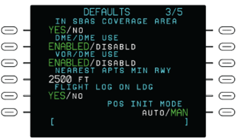
The DEFAULTS 3/5 page shows default settings for VOR and DME sensor usage by the FMS when it is calculating the position. Use the DEFAULTS 3/5 page to change the individual default settings for:
- DME USAGE.
- VOR USAGE.
The selected setting on the DEFAULTS 3/5 page affects the setting on the VOR/DME CONTROL page.
Use the IN SBAS COVERAGE AREA selection (YES/NO) to turn off the SBAS message. This message is triggered sometimes when between coverage areas (for example, crossing the ocean).
The DEFAULTS 3/5 page is also used to set the minimum runway length for the NEAREST APTS page. The NEAREST APTS page shows a list of the nearest airports that have runways that meet or exceed the length of the minimum runway length value designated in the NEAREST APTS MIN RWY field on the DEFAULTS 3/5 page.
The DEFAULTS 3/5 page also shows default setting for display of the FLIGHT LOG after landing (FLIGHT LOG ON LDG). Use the DEFAULTS 3/5 page to change the individual settings for automatic display of the FLIGHT LOG page.
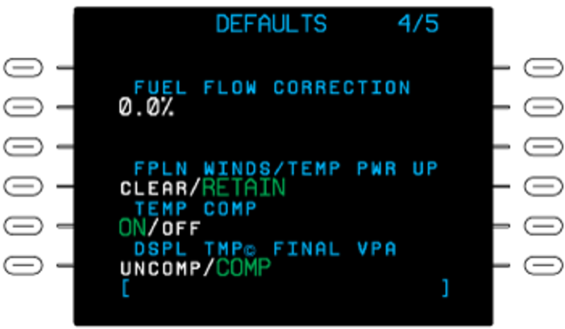
The DEFAULTS 4/5 page shows default values and settings for performance related information. Use the DEFAULTS 4/5 page to change the default values/settings for:
- FUEL FLOW CORRECTION – Used to set the default fuel flow correction factor that is used for fuel calculations.
- FPLN WINDS/TEMP PWR UP – Controls the option at system power up to CLEAR or RETAIN wind and temperature data previously entered into a flight plan.
- TEMP COMP – Controls the option at system power up to have the optional temperature compensation function ON or OFF.
- DSPLTMP© FINAL VPA – Controls the option to have the Vertical Path Angle (VPA) for the final approach segment to be shown as either an Uncompensated (UNCOMP) or Compensated (COMP) value. Changes to the FUEL FLOW CORRECTION default value cause an immediate change to the FUEL FLOW CORRECTION value that shows on the PERF INIT 3/3 page.
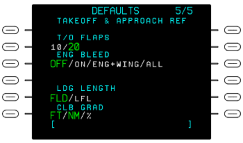
The DEFAULTS 5/5 page shows default values and settings for the Vspeeds values that show on the TAKEOFF REF and APPROACH REF pages. Use the DEFAULTS 5/5 page to change the default values/settings for:
- Flaps set for take off (T/O FLAPS).
- Engine Bleed (ENG BLEED) configuration.
- Landing Length (LDG LENGTH) display format as either Landing Field Length (LFL) or Actual Landing Distance (ALD). A Landing Factor (LDG FACTOR) data line shows when ALD is selected.
- Climb Gradient (CLB GRAD) display format as either Feet per Nautical Mile (FT/NM) or as a percentage (%). Fields on the TAKEOFF REF and APPROACH REF pages are also set to their selected default settings after a FMS cold start.
ACT ARRIVAL DATA Page
Pushing the ARR DATA line select key on the INDEX page shows the ACT ARRIVAL DATA page. The ACT ARRIVAL DATA page shows the approach data at the arrival airport as available in the database.
The ACT ARRIVAL DATA page supplies the flight crew with the following data:
- Arrival airport (ARR AIRPORT) identification
- Approach FREQ (frequency)
- Approach (APPR) data:
- ILS identification
- GS (glideslope) ANGLE value
- LOC (localizer) TRUE BEARING value
- RWY (runway) THRESHOLD distance
If no destination airport has been entered, all display fields are blank. If no approach is selected, only the four-letter ICAO airport identifier shows. If a non-precision approach has been selected, the approach designation and runway, and runway threshold altitude also show. If an ILS approach is selected, the glide slope angle, localizer true bearing, and localizer frequency show in addition to the information already described. Both approach types will indicate if the airfields are WGS-84 compliant. The information presented on the ARRIVAL DATA page is for display only. To change the display, select a new approach at the destination airport through the ARRIVAL page.
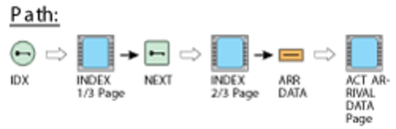
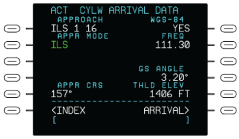
TEMP COMP Page
Barometric altimeters are calibrated to indicate true altitude only under ISA conditions of temperature and sea level pressure. In cases where the temperature is higher than ISA, the true altitude will be higher than the altitude indicated by the altimeter. Conversely, when the temperature is lower than ISA, the true altitude will be lower than indicated. The FMS flies VNAV on a non-precision approach using the barometric altimeter for the altitude sensor. On a day when the temperature is lower than ISA, the true altitude/VPA flown by the aircraft will be below the published altitude/VPA unless the appropriate constraint altitudes and vertical path angles are compensated to account for the below ISA temperature condition.
The FMS Temperature Compensation (TEMP COMP) feature supplies the pilot with a mechanism to have the FMS automatically compensate the altitude constraints and vertical path angles associate with the approach, the approach transition, and the missed approach.
The Outside Air Temperature (OAT) value must be entered before temperature compensation can be computed. A valid OAT is in the range from –55 °C to 70 °C. The OAT entered and shown is the aerodrome temperature that is associated with the airport that is selected through the SEL APT LSK. Upon initial entry of a new OAT value, the FMS will calculate ISA DEV using the value entered for OAT and the elevation of the associated airport. When ISA DEV is equal to or less than 0 °C (cold temperature), the OAT value is accepted for temperature compensation and calculations are shown. The OAT value is shown in large white font. The calculated ISA DEV is shown in small white font.
When ISA DEV is greater than 0 °C (hot temperature), the OAT value is shown in large yellow font and the calculated ISA DEV is shown in small yellow font. The message CORRECT APPR ALT DOWN? and the options CONFIRM and CANCEL are shown in large white font. Pushing the CONFIRM LSK will cause the FMS to accept the OAT value for temperature compensation calculations and show OAT and ISA DEV in white font. Pushing the CANCEL LSK will cause OAT and ISA DEV to be returned to their previous states.
Note:
The CORR APPR ALT DOWN? prompt refers to the indicated altitudes and not the true altitudes.
When TEMP COMP is active, the FMS adds a copyright symbol (©) to signify when temperature compensation has been applied to a waypoint constraint altitude or VPA. If a compensated altitude constraint is shown in other places on the CDU or MFD display (for example, the VNAV window), then the copyright symbol will be shown there as well. TMP© shows in white on the bottom CDU annunciation line while TEMP COMP is active and being applied to appropriate altitude constraints.
If TEMP COMP is ON and the FMS has all the information it needs to calculate temperature compensation, any VPA or altitude constraint that is loaded from the navigation database as part of an approach procedure, an approach procedure transition, or missed approach procedure, will be temperature compensated automatically. Exceptions that result in TEMP COMP not being applied include altitude constraints that are above the flight level transition altitude, and manually entered altitude or VPA constraints.
Note:
Temperature compensation is not applied to altitudes above the flight level transition altitude. But when the FMS is applying TEMP COMP to an altitude below the transition altitude, it is possible that the resulting altitude can be above the transition altitude. These situations will result in a flight level altitude with a copyright symbol (©), which indicates a temperature compensated flight level altitude. Since flight level altitudes are rounded to the nearest hundredths, the indicated altitude is not the corrected true altitude.
Note:
The temperature compensated VPA display on the ACT/MOD LEGS pages is the value that results from the temperature compensated altitude and is not the actual VPA that the aircraft will fly. When temperature compensation is active, the aircraft will always fly the actual VPA contained in the database for that approach.
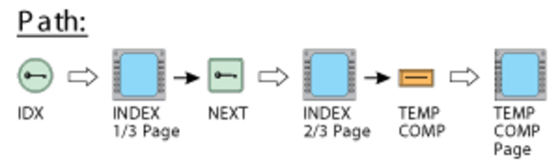
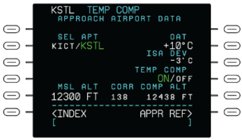
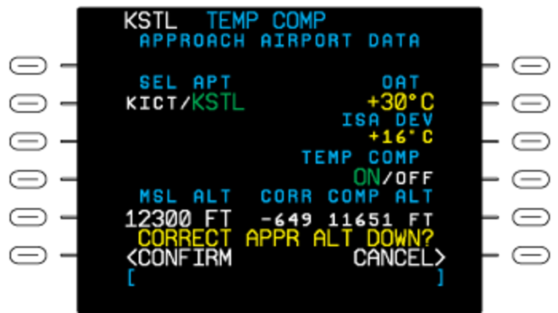
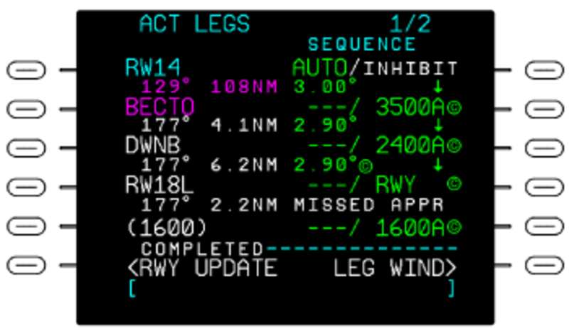
LRN POS DATA Page
The LRN POS DATA line select key on the INDEX 3/3 page, when pushed, shows the LRN POS DATA page. Page 1/2 displays the current computed positions of each installed GNSS long range sensors and the FMS. When FREEZE is selected, all data displayed is frozen. When UPDATE is selected all data on the page is updated. The default is UPDATE when this page is accessed.

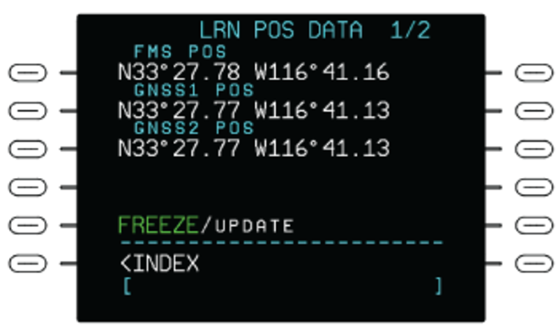
Page 2/2 displays the current computed positions of each installed IRS and the FMS. When FREEZE is selected, all data displayed is frozen. When UPDATE is selected all data on the page is updated. The default is UPDATE when this page is accessed.
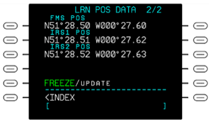
02/02/16
CDU Pages (Access with the Function Keys)
The CDU pages show when a CDU function key is pushed. The CDU pages access control and display functions of the flight plan in operation. These CDU pages supply the following:
- Active flight plan data (FPLN, LEGS, DIR, and DEP/ARR keys)
- Operation and performance data (PERF key)
- FMS messages (MSG key)
- Radio control functions (TUN key)
- MFD display control functions (DSPL MENU, MFD DATA, and MFD ADV keys)
The primary CDU pages opened with the CDU function keys and the related data are described in the following sections.
ACT FPLN Page
Pushing the FPLN key on the CDU shows the ACT FPLN (active flight plan) page. The ACT FPLN pages show display/control functions related to the active flight plan. The active flight plan can include:
- Airways
- Standard instrument departures (SIDs)
- Standard terminal arrival routes (STARs)
- Approaches
- Holding patterns
- Direct flight legs
- Origin airport and destination airport data
- Pilot specified waypoints
- Parallel offsets
If personnel have not put a flight plan into operation, the FPLN key makes the selection of the first flight plan page. Only the active flight plan can then supply the outputs of FMS flight-guidance steering-commands.
The first data line contains the ORIGIN and DEST (destination) airports and the flight plan DIST (distance) between the two. The second data line contains the ROUTE name and the ALTN (alternative) destination selection.
The ORIGIN, DEST, and ALTN data fields let the pilot/copilot make entries for the origin airport, destination airport, and alternative airports (as KCID/KDEN). The ROUTE data field lets the pilot/copilot make an entry of a route name. The route can contain an origin airport, destination airport, arrival/departure runways, and flight legs that connect. ROUTE, ORIGIN, DEST, or ALTN data is recorded on the scratchpad line. Then, a line select key is pushed to move this data to a data field.
On the ACT FPLN page, the entry immediately below the VIA label, shows a flight leg that goes directly to the way point shown in the related TO data field. The flight plan in operation automatically sequences as the aircraft moves along the flight path. It does this if FMS is set as the navigation source for the flight. Flight-plan way points are saved as history data as the aircraft moves through them.
The other line select keys, on the ACT FPLN page, supply the functions that follow:
- The COPY ACTIVE line select key is used to make a copy of the active flight plan into the second flight plan (SEC FPLN)
- The SEC FPLN line select key, when pushed, gives access to the SEC FPLN page
- The PERF INIT line select key, when pushed, gives access to the PERF INIT (performance initialization) page of the active flight plan
To make or change a flight plan, the pilot/copilot first makes an entry of a way point identification on the scratchpad line. Then a right-side line select key is pushed to move the identification to the applicable data line. This data line sets a flight leg that goes directly to the way point. The pilot/copilot must do this procedure again for each way point in the flight plan. Way point identifications (KCID, KFNB, etc.) are saved in the system navigation data base. The CLR/DEL key erases a display line of the flight plan.
If the flight plan that is in operation is changed, the system makes a changed copy of that flight plan, and the flight-plan page title changes to MOD FPLN (modified flight plan). The change is made on the MOD FPLN page.
Note:
The MOD FPLN page is similar to the ACT FPLN page. Only the function of the left bottom line select key is different: in the MOD FPLN page, it supplies a cancel modification (CANCEL MOD) selection that can be used to cancel the changes.
There is no access to the flight plan that is in operation when there is a changed flight plan. The changed flight plan lets the pilot/copilot change the flight plan and see the results before the change is put into operation. To put the changed flight plan into operation, personnel must push the EXEC key. This causes the first way point of the changed flight plan to become the way point in operation. The pilot/copilot must make sure that this way point is correct before the change is put into operation.
The dual FMS system operates in the SYNC mode by default, changes to a flight plan that is not in operation, immediately moves to the opposite-side FMS. But, changes to the flight plan that is in operation moves to the opposite-side FMS only after the EXEC key is pushed.
The dual FMS system does not operate in the INDEP mode.

ACT LEGS Page
Pushing the LEGS key on the CDU shows a flight plan LEGS page. The flight plan LEGS pages give details of each flight plan leg.
The title line on the flight plan LEGS page can be LEGS, ACT LEGS, or MOD LEGS:
- If no flight plan is in operation, the LEGS key is pushed to show the (first flight plan) LEGS page
- If a flight plan was put into operation, the LEGS key is pushed to show the ACT LEGS page
- If there is a changed flight plan, the LEGS key is pushed to show the MOD LEGS page
The ACT LEGS pages show navigation data for each flight leg in the flight plan. The ACT LEGS page shows the flight leg on which the aircraft moves as the first flight leg. Flight legs can be changed on this display page (the title changes to MOD LEGS page). The change procedure is almost the same as that given for the flight plan pages.
Note:
The MOD LEGS page is similar to the ACT LEGS page. Only the function of the left bottom line select key is different: in the MOD LEGS page, it supplies a cancel modification (CANCEL MOD) selection that can be used to cancel the changes.
The active leg data is magenta. The from way point is cyan, and the other way point data is white. The flight leg distance is the great circle distance from the aircraft to the way point that is in operation.
The SEQUENCE line select key on the ACT LEGS page, lets the flight enable automatic leg sequencing or inhibit leg sequencing. AUTO is the default selection. With the AUTO selection, the FMS automatically sequences active flight plan legs. When the selection is set to INHIB, the FMS inhibits leg sequencing.
The ACT LEGS page contains a display line for each flight leg of the flight plan. This display line shows the way point identification for that flight leg with course and distance data. Each display line also contains two data fields (adjacent to the right line select keys) that are used to make an entry for airspeed and/or altitude limits at that way point. These values are for flight crew only and the FMS does not use them for calculations. The right line select keys move the data entered in the scratchpad line to the related data field.
The LEGS page has LEG DATA and LEG WIND selections that give access to more data on the legs in the flight plan. Also, the LEGS page will have a HOLD AT display if the access to the page is from the ACT FPLN HOLD page to enter new holding-pattern data.

ACT DIRECT-TO Page
Pushing the DIR key on the CDU shows the ACT DIRECT-TO page. This page allows a direct-to change or a course change on a flight leg. The pilot/copilot can do a direct-to change or a course change only on the flight leg of the flight plan that is in operation.
The ACT DIRECT-TO page is almost the same as the LEGS page. It has the lateral way points on the left side and vertical data on the right side of the display. The entry (on the scratchpad line) of a way point (that is off of the flight plan) and a selection of the top left line select key, makes a direct-to course to the diversion way point. A selection of the other left line select keys does a lateral direct-to the adjacent flight plan way point.
The selection of a right line select key does a vertical direct-to the altitude at the related lateral way point.
The vertical direct-to keeps the initial lateral path, but causes the aircraft to move immediately up or down to the vertical point selection.
A direct-to change to the flight plan makes a flight leg that is a great circle path from the aircraft position to a way point. The calculated great circle path makes a sufficient area to turn the aircraft from its heading to the necessary heading.
The line select key adjacent to a way point on the ACT DIRECT-TO page (RWF for example), when pushed, shows the MOD LEGS (modified legs) page on the CDU display. The course angle above the way point shows the course between the current aircraft position and the way point. The INTC CRS (intercept course) data shows the course angle that the flight plan entered the way point.
The INTC CRS course angle can be changed through a new course-angle input in the scratchpad. The INTC CRS line select key, when pushed, sets the course angle for the direct-to way point. The EXEC key, if pushed, will change the active flight plan and the ACT LEG page will show the new direct-to leg.
If the direct-to way point selection is on the flight plan, all way points between the previous active way point and the direct-to way point are removed from the display. These way points are moved to the history memory buffer. If the direct-to way point selection is not on the flight plan, a discontinuity is recorded after this way point.

DEP/ARR INDEX Page
Pushing the CDU DEP/ARR key shows one of the following control/display pages:
- DEP/ARR INDEX page
- ARRIVAL page or DEPART page, as applicable
The DEP/ARR INDEX, ARRIVAL, and DEPART pages let the flight crew put a SID, STAR, or runway into the flight plan. If the DEP/ARR key is pushed while the SEC FPLN or SEC LEGS page is shown on the display (or if origin or destination airports are not specified), the DEP/ARR INDEX page shows.
The DEP/ARR INDEX page shows names of the origin/destination airports (if on the flight plan pages) for the active flight plan and the second flight plan. This page shows a list of airports for the active flight plan (below the ACT FPLN label) and for the second flight plan (below the SEC FPLN label).
The flight crew can use the left and right line select keys on this control/display page to open and set a departure page or an arrival page for an airport that is on the list. Also, the pilot/copilot can add an another airport to the list shown on the DEP/ARR INDEX page. The new airport name is entered in the scratchpad line and then the bottom DEP or ARR line select key is pushed to move the name to one of the data fields below the OTHER label.
On the DEP/ARR INDEX page, the flight crew can push the DEP line select key adjacent to an airport name to show a DEPART page for that airport. The DEPART page gives a list of the names of available SIDs in alphabetical sequence, and the available runways in numerical sequence.
To put an SID or runway into the flight plan, the pilot/copilot does the selection of the applicable SID/runway and then pushes the EXEC key.
On the DEP/ARR INDEX, the flight crew can push the ARR line select key adjacent to an airport name to show the ARRIVAL page for that airport. The ARRIVAL page gives a list of the names of available STARs in alphabetical sequence, and the available approaches or runways in numerical sequence.
To put a STAR or runway into the flight plan, the pilot/copilot does the selection of the applicable STAR/approach/runway and pushes the EXEC key.
If the DEP/ARR key is pushed while the SEC FLPN or SEC LEGS is not shown on the display, then the DEPART or the ARRIVAL page of the active flight plan will show.
One of these two pages will show (in relation to the aircraft position) as follows:
- If the aircraft is on ground, the DEPART page of the origin airport will show
- If the aircraft is in flight, the ARRIVAL page of the origin airport or the ARRIVAL page of the destination page will show in relation to the flight phase
When the aircraft is in flight, the applicable ARRIVAL page shows (in relation to the flight phase) as follows:
- The ARRIVAL page of the origin airport shows, if the aircraft is less than half of the distance to the destination airport and less than 50 NM from the origin airport
- The ARRIVAL page of the destination airport shows, if the above condition is not true

PERF MENU Page
Pushing the PERF key on the CDU shows the PERF MENU page. The PERF MENU page lets the flight crew set/show parameters related to the aircraft performance, fuel management, vertical navigation, and flight log functions. The flight crew pushes the PERF INIT line select key on the PERF MENU page, to see the ACT PERF INIT (active performance initialization) page.
The ACT PERF INIT page lets the flight crew record a cruise altitude, transition altitude, or flight level. This page shows data below the following labels:
- BOW (basic operating weight)
- PASS/WT (average passenger weight)
- CARGO
- FUEL
- CRX ALT (cruise altitude)
- ALTN CRZ ALT (alternative cruise altitude)
- ZFW (zero fuel weight)
BOW and PASS/WT are set to the initial system values. ZFW is recorded directly or calculated from the basic operating weight, number of passengers, passenger weight, and cargo weight. Gross weight is recorded directly or calculated from the zero fuel weight entry after the fuel weight has an initial value.
The flight crew can record an altitude on the scratchpad line, then push the CRZ ALT line select key to set cruise altitude. An entry can be as altitude (–1,300 to 65,000 ft) or as a flight level (FL0 to FL650). The alternative cruise altitude is given for planning functions.
The flight crew pushes the FUEL MGMT line select key on the PERF MENU page to show the FUEL MGMT (management) page 1. Pushing the NEXT key shows the FUEL MGMT page 2. The FUEL MGMT page 1 and page 2 show data for fuel that is on the aircraft:
- FUEL (total in lbs)
- FUEL FLOW (measured total fuel flow or pilot-specified fuel flow in lbs/hr)
- RESERVES fuel allocation (in lbs)
- GND SPD (measured/pilot-specified ground speed)
- TIME TO RESERV (time to reserves fuel)
- RNG TO RESERV (range to reserves fuel
- SP RNG (range in NM/lb)
- Measured FUEL FLOW for each engine (lbs/hr)
- FUEL USED for each engine (lbs)
- TOTAL fuel flow (lbs/hr)
Pushing the NEXT key again shows the PERF TRIP page. The PERF TRIP page supplies the functions of time, distance, and fuel calculator. The flight crew records the FROM waypoint and TO waypoint to find estimates of:
- DIST (in NM)
- ETE
- FUEL FLOW (in pounds/hour)
- FUEL REQ (fuel quantity that is necessary between locations)
Values for ground speed (GND SPD) and FUEL FLOW show on the display. The flight crew can override these values. The PPOS function records the location in a latitude/longitude display pattern as the FROM waypoint in the calculation. Pushing the VNAV SETUP line select key on the PERF MENU page shows the ACT VNAV CLIMB page. The PREV key or NEXT key shows the ACT VNAV CRUISE page and ACT VNAV DESCENT page.
The TGT SPEED for each part of the flight can be changed on the VNAV pages for the flight plan in operation. It is possible to change or erase the SPD/ALT LIMIT for the climb and descent parts of the flight.
Pushing the FLT LOG line select key on the PERF MENU page shows the FLIGHT LOG page. The FLIGHT LOG page gives a summary of the flight until power is removed or the aircraft takes off for another flight. To delete related fuel data, record DELETE or zero in the scratchpad line and push the line select key adjacent to FUEL USED label (no other data entry is permitted).
The ENABLE/DISABLE line select key on the PERF MENU page, makes/cancels the selection of the advisory VNAV displays. The data field adjacent to the KT legend gives the VNAV planned reference speed (dashes show when VNAV is not valid).
The SEC PERF line select key on the PERF MENU page, sets performance initialization for a second flight plan.


MESSAGES Page
When there is a message related to the FMS functions, a MSG annunciation shows on the PFD/MFD. This indicates additional information on the MESSAGES page. The FMS annunciations are described in the PFD/MFD FMS displays section.
Pushing the MSG key shows the MESSAGES page. The MSG key also accepts new messages.
New messages are shown below the NEW MESSAGES line. Messages that have shown before are below the OLD MESSAGES line. All messages that are on the MESSAGES page are accepted. These messages are put into position below the OLD MESSAGES line when the MESSAGES page is shown again.
When the MESSAGES page shows and the messages are accepted, the CDU page that was on the display immediately before, shows on the display again. The CDU annunciation line and/or the MESSAGES page can contain the FMS messages and indications that follow (messages are shown in amber or white, in relation to the priority of the message).
| MESSAGES | DESCRIPTION |
|---|---|
| AFIS FPLN LOADED(white) | The flight crew made a selection for AFIS flight plan but has not had a view of the selection |
| ALT(white) | Shows when the aircraft is unable to meet altitude constraints during a climb or descent |
| APPR FOR REF ONLY(white) | This is an approach that is not approved for FMS guidance |
| BOC (bottom of climb)(flashing white) | Shows when the aircraft is 5 sec prior to the BOC |
| BOC (bottom of climb)(steady white) | Shows when the aircraft is 1 min prior to the BOC |
| CHECK FPLN ALT(white) | Possibly there is an error in the altitude limits that show in the flight plan |
| CHECK LOC TUNING(white) | The ILS approach is set, the FMS tried to tune the localizer, and cannot tune the localizer |
| CHECK NAV SOURCE(white) | The EFIS NAV source is not FMS or LOC after FMS locks on to ILS |
| CHECK NAV TUNING(white) | The radio navigation (RNAV) approach is set, the FMS has tried to tune the reference navaid, and cannot tune the reference navaid |
| CHECK ALT SEL(white) | The preselector is not set to another altitude 45 sec before it has the vertical switch point |
| CHECK SPEED(amber) | The airspeed is too high for the holding pattern or the VNAV speed limit |
| CHK DATA BASE DATES(white) | The active data base date of the opposite-side FMS is not the same as the active data base date |
| CHK PERF DATA BASE(white) | The FMS performance data base configuration is not related to the aircraft type, or same-side and opposite-side configurations are different |
| CHK POS(amber) | The FMC finds that the position precision is less than the precision necessary for the certification of this part of the flight |
| CRS REVERSL IN FPLN(amber) | The flight plan has a course reversal of more than 160 degrees at the TO way point |
| DISCONTINUITY(white) | Shows in the middle of the HSI display when the active leg of the flight plan is a discontinuity |
| DME-FMS DISAGREE(amber) | The FMS finds that the DME measurements are not the same at all times |
| EXEC FPLN MOD(amber) | There is a changed flight plan and the flight crew does not use the CDU keyboard for 15 sec |
| FMS DR(amber if in flight more than 2 min, otherwise white) | The FMS is in dead reckoning mode because it cannot find position sensor data |
| FMS DR FOR 5 MIN(amber) | The FMS is in dead reckoning mode for more than 5 min while airborne |
| FMS-FMS DISAGREE(amber) | The opposite-side FMS position is different from the same-side FMS position |
| FMS INDEPENDENT OP(white) | The related operation of the two FMSs in a system is disconnected while airborne |
| FMS NAV INVALID(amber) | The FMS is in the dead reckoning mode for too much time |
| FPLN DISCONTINUITY(amber) | The flight plan has moved through a way point to a flight plan discontinuity |
| GPS DISABLED(amber) | The system cannot use GPS data because the flight crew sets this condition on the GPS CONTROL page. This condition can prevent accurate navigation |
| GPS-FMS DISAGREE(amber) | The GPS used to calculate an estimate for position has data that is different from the data in the FMS |
| GPS NOT AVAILABLE (amber if in destination terminal area, otherwise white) | The GPS position measurements are not used in the FMS position solution |
| GPS ONLY(white) | Shows when the navaids or IRS sensors are not available for use by the FMS, and the approach is not SBAS (LPV or L/V) |
| HALF-BANK SELECTED(amber) | The half-bank mode is set and the aircraft will go through the hold fix in less than 1 min |
| HOLD(white) | Shows when the holding pattern is active |
| HOLD EFC EXPIRED(white) | The flight crew did not get clearance from air traffic control (ATC) in the correct time limit to make an exit of the holding pattern |
| INITIALIZE POSITION(amber) | It is necessary to set initial position for the inertial navigation unit |
| IRS ONLY(white) | The FMS only uses position data from the IRS sensors and the calculated position error exceeds 0.442 NM |
| LAST WAY POINT(amber) | The aircraft moves through the last way point of the flight plan |
| LOSS OF INTEGRITY(white) | Shows when the aircraft is above 400 feet AGL after takeoff even when the GNSS sensor is enabled |
| LOSS OF INTEGRITY(amber) | Shows when the GNSS sensor is disabled and the aircraft is above 400 feet AGL |
| LOW ALTITUDE(amber) | Shows when the current GNSS height is lower than the desired GNSS height at the FAF by more than 50 meters + vertical altitude limit (VAL) |
| NO APPR GPS RAIM(white) | The approach GPS RAIM is not available |
| NO FLIGHT PLAN(white) | There is no selection made for the flight plan that is in operation |
| NO GPS RAIM (white) | The GPS receiver autonomous integrity monitoring (RAIM) is not available |
| NO NAV DATA BASE(white) | There is no navigation data base saved in the FMC |
| NO PERF DATA BASE(white) | There is no performance data base saved in the FMC |
| NOT ON INTERCPT TRK(amber) | The FMS gives steering commands to move the aircraft back to the flight leg. But, the flight track will not move through this flight leg of the flight plan.This message can also give an indication that the FMS is armed for capture. But, at this heading, the aircraft path will not move through the flight leg. |
| OFFSET TERMINATED(white) | Cancels steering commands to a parallel offset path |
| OFFSET WILL END(white) | The system will stop steering commands to a parallel offset path in 2 min |
| PERF OUT OF RANGE(amber) | Estimates for performance conditions such as airspeed, weight, or the altitude is more than the maximum limit of performance data base contents |
| PROGRAM DIFFER(white) | The two FMCs have different software programs or have software programs that cannot operate together |
| RE-ENTER SET POS(amber) | It is necessary to give initial values or other long range navigation (LRN) functions (or give the initial values again), and the SET POS was done |
| RESET INITIAL POS(amber) | It is necessary to update the position with the POS INIT page |
| SPD(amber) | Shows when the following conditions are true: VNAV is valid and the current speed limit is associated with a holding pattern that is active within 2 minutes VNAV speed limit due to a speed constraint exists and the speed is more than 20 knots IAS or 0.03 Mach above the VNAV computed required speed |
| TOD (top of descent)(flashing white) | Shows when the following conditions are true: the active VNAV sub-mode is VPATH and the level sub-mode is active VPATH conditions are for capture are satisfied bottom of current descent path is below barometric altitude VNAV reference altitude equals altitude constraint at the bottom of the descent path hold pattern is not between aircraft and TOD time to dynamic TOD is less than or equal to 5 seconds to capture the descent path a vertical direct-to command has not been received with the last 10 seconds |
| TOD(steady white) | Shows when the following conditions are true: the active VNAV sub-mode is VPATH and the level sub-mode is active VPATH conditions are for capture are satisfied bottom of current descent path is below barometric altitude VNAV reference altitude equals altitude constraint at the bottom of the descent path hold pattern is not between aircraft and TOD time to dynamic TOD is less than or equal to 60 seconds to capture the descent path a vertical direct-to command has not been received with the last 10 seconds |
| UNABLE CRZ ALT(white) | The performance estimates show that the aircraft cannot move to the cruise altitude |
| UNABLE FPLAN ALT(amber) | The performance estimates show that the aircraft will take too much time to move to the climb altitude limit or descent altitude limit |
| UNABLE NEXT ALT(amber) | The aircraft will move to an altitude that is more than an altitude limit |
| UNABLE TO SEQ FPLN(white) | The FMS cannot move through the flight plan because the end of the flight leg is not found |
| UNABLE VHF NAV TUNE(white) | The FMS cannot automatically tune the ILS approach station because the related VOR/DME radio is set as an active navigation source |
| USE LNAV MINIMUM(amber) | Shows when the LPV navigational accuracy does not support LPV minimums but will support LPV minimus as published. This condition exists when ALL of the following conditions are true: the FMS is in SBAS-VNAV approach mode the LNAV level of service is authorized for the selected approach |
| V/D ONLY(white) | Shows when the FMS is using a single VOR/DME for position estimation and the navaid is less than 40 NM away from the present position |
| VNAV SENSOR FAIL(white) | Important VNAV sensor data is not available |
| VOR/DME DISABLED(white) | The VOR CONTROL page is set so that the system does not use VOR data and DME data. This can prevent accurate navigation |
| VOR/DME DIST > 75 NM(amber) | The FMC does the navigation in the terminal area and uses one VOR/DME station that is greater than 75 nmi |
| VOR-FMS DISAGREE(amber) | The FMC finds that all received VOR measurements are not the same as the position estimate |
| XTALK FAIL(white) | There is a fail condition in the cross-talk communication in a system that has two FMSs |

TUNE Pages
Pushing the TUN key on the CDU shows the TUNE page. The TUNE pages tune the communication and navigation radios and/or control their operation modes. The TUNE pages also accesses other CDU pages that give more radio control/display functions. The control/display functions shown on the TUNE page 1/2 and TUNE page 2/2 and other related radio control/display pages are described in the applicable sections that follow:
- VHF communication system for COM1, COM2, COM3, PRESET, RECALL, and ADF functions
- HF communication system for HF1, HF2, and HF3 functions
- SELCAL system for the SELCAL function
- DATALINK
- TCAS system for the ATC/TCAS function
- VHF navigation system for NAV1 and NAV2 functions
- DME system for DME1 and DME2 functions
- ATC transponder system for ATC1 and ATC2 functions


MFD Display Control Pages
The CDU keys that access the display control functions are the DSPL MENU key, MFD DATA key, and MFD ADV key. These keys are used in relation to the CDU pages that allow control of the MFD text and map displays. These are:
- DISPLAY MENU pages
- DISPLAY ADVANCE pages
DISPLAY MENU Pages
The DSPL MENU key on the CDU, is used to show a menu of display options for the MFD. When pushed, the DSPL MENU key shows the
(LEFT or RIGHT) DISPLAY MENU page which gives one of the menus that follow:
- MAP DISPLAY menu, if the MFD display is a plan map or a position map
- TEXT DISPLAY menu, if the MFD display is a text data page
Note:
The SIDE L/R line key on the DISPLAY MENU page is used to set which MFD (left [L] or right [R]) is to be controlled.
If the MFD does not show a map or text data display, and the DSPL MENU key is pushed, the DISPLAY MENU page for the position map will show. The MAP DISPLAY menu page gives a list of available background map symbols. The list also shows functions related to the plan map or position map. On the MAP DISPLAY page, the items for which a selection is made, show in large green symbols.
The MAP DISPLAY menu (page 1/2) gives the following list of items:
- HI NAVAIDS
- LO NAVAIDS
- INTERS (airway intersections)
- ARPTS (airports)
- TERM WPTS (terminal waypoints)
- NDBS (nondirectional beacon system)
- ETA (estimated time of arrival at waypoints)
- SPEED
- ALTITUDE
- MISS APPR (missed approach)
This menu page also contains a WINDOW line select key. Pushing this line select key to alternatively shows and does not show the MFD data window. Pushing the NEXT function key selects page number 2 of the MAP DISPLAY menu. The selections on the MAP DISPLAY menu (page 2/2) are as follows:
- RNG: ALT SEL (range-to-altitude selection)
- LRN POS (long-range navigation position)
- ALTN FPLN (alternative flight plan)
The TEXT DISPLAY menu page gives the list of the available text-data pages. The selected items show in large green symbols.
The TEXT DISPLAY menu contains the following text page selections:
- FPLN PROG (flight plan progress)
- NAV STATUS (navigation status)
- POS SUMMARY (position summary)
- POS REPORT (position report)
- SEC FLPN (second flight plan)
- VOR STATUS
- LRN STATUS (if LRN sensors are installed)
The MFD DATA key on the CDU, is used to control which DISPLAY MENU page shows on the CDU. The available DISPLAY MENU pages are the MAP DISPLAY MENU page and the TEXT DISPLAY MENU page.
Each time the MFD DATA key is pushed, it alternately does the selection of one of the two DISPLAY MENU pages. The MFD DATA key shows data on the same-side MFD.

DISPLAY ADVANCE Pages
The MFD ADV key on the CDU moves through MFD text pages or moves the FMS plan map center point on the FMS map plan. Pushing the MFD ADV key shows the LEFT DISPLAY ADVANCE page or the RIGHT DISPLAY ADVANCE page.
Note:
The SIDE L/R line key on the DISPLAY ADVANCE page, sets which MFD (left [L] or right [R]) is to be controlled.
The LEFT or RIGHT DISPLAY ADVANCE page can show one of the following two menus:
- PLAN MAP CENTER menu (sets a waypoint as a map display center)—If the MFD shows a plan map or present position map
- TEXT DISPLAY menu (shows previous or next page)—If the TEXT DISPLAY on the MFD has more than one control/display page
The PLAN MAP CENTER menu has the following line select keys:
- PREV WPT
- NEXT WPT
- TO WPT
The PREV WPT line select key, when pushed, moves the way point, that was used before, to the middle of the MFD display.
The NEXT WPT line select key, when pushed moves the subsequent way point to the middle of the MFD display.
The TO WPT line select key, when pushed, moves the TO way point to the middle of the MAP display.
Also, the flight crew can record a way point identification below the CTR WPT label. Then, if the adjacent line select key is pushed, it will move that way point to the middle of the MAP display.
On the TEXT DISPLAY menu page,
- The flight crew can push the PREV PAGE line select key to change the MFD text page. The text page changes to the text page that was shown on the display immediately before.
- The flight crew can push the NEXT PAGE line select key to change the MFD text page to the subsequent display page. The NEXT PAGE line select key does not operate if the text data contains one display page.

02/02/16
PFD/MFD FMS Displays
The FMS supplies functions that can show:
- FMS map and text displays
- FMS annunciations on the PFD and MFD
- Different FMS navigation data on the PFD and MFD
FMS Map and Text Displays
The FMS supports the display of present position map (PPOS) on the PFD. It supports PPOS and plan maps (two-dimension and optional three-dimension) on the MFD. When the PFD data is the selection, map data is shown on the PFD and text data is not available. The FMS supports the display of several text pages on the MFD. The selection of a specific text page for display on the MFD is done on the LEFT/RIGHT DISPLAY MENU page.
FMS Annunciations
The FMS annunciations show on three display lines located between the top and bottom areas of the PFD and MFD displays on the right side. The FMS annunciations can show in amber or in white in relation to the annunciation priority and/or the flight data type. When an FMS annunciation shows on the top line, it first flashes for 5 sec and then stays stable. The FMS annunciation shows only if the FMS is the navigation source shown on the applicable PFD.
When there is a message related to these FMS annunciations, MSG shows in the second line to indicate additional information on the MESSAGES page. Two types of annunciations can show on the second line:
- Clearable annunciations that can be removed when the MESSAGE page is opened.
- Non-clearable annunciations that cannot be removed until the related condition becomes not true.
The third line is for annunciations that give operational status of the FMS.
Navigation Source
The first line of the active navigation source data identifies the navigation source (VOR1, VOR2, LOC1, LOC2, FMS1, FMS2, or FMS). If the navigation source is FMS, FMS1, or FMS2, its color is magenta. When EFIS energizes, it uses the last navigation source that was set when it was previously operated.
Course/Desired Track
The second line of the active navigation source data identifies the course/desired track selection. When the FMS is the navigation source, DTK (desired track) or HDG (heading) shows on this line. The FMS controls selection of HDG or DTK. A 3-digit course or track value shows to the right of the HDG or DTK identifier. If FMS HDG or DTK data becomes incorrect, the digital course/desired track value changes to dashes (---).
Active Station or Waypoint Identifier
The third line of the active navigation source data shows the active station or waypoint identifier (KCID, for example). The identifier can have a maximum of seven letters/digits.
Time-To-Go
The fourth line of the active navigation source data shows the time-to-go (TTG) with the time (in minutes and seconds) to the station or waypoint. The time is removed (not the TTG legend) if the TTG data word is not there or the TTG data word SSM (sign status matrix) bits give a fail indication. The time shows as --.-- if the TTG data word SSM bits give an NCD (no computed data) condition.
Distance to Active Station/Waypoint/Runway
The fifth line of the active navigation source data shows the distance to the active station, waypoint, or runway (if LOC). If the navigation source is FMS, distances of 0 through 9,999 nm can show. Dashes (----) show in place of the FMS distance when the value is more than 9,999.
Bearing Sources
On A/C Pre SB 350-34-001, the possible number 1 bearing-pointer selections are FMS1, VOR1, ADF1, or OFF. The possible number 2 bearing-pointer selections are FMS2, VOR2, or OFF.
On A/C Post SB 350-34-001, the possible number 1 bearing-pointer selections are FMS1, VOR1, ADF1, or OFF. The possible number 2 bearing-pointer selections are FMS2, VOR2, ADF 2, or OFF.
The bearing-source indications show in the lower left corner on the PFDs and MFDs. The number 1 bearing-source indications shows in cyan, and the number 2 bearing-source indications shows in white.
The bearing identification shows the station identifier or frequency of the VOR or ILS, the way point of the FMS, or the frequency of the ADF. The bearing identification shows below the bearing source annunciation. The letter T follows the bearing identification when the bearing source is VOR and true heading is set.
The bearing icons are small bearing pointer symbols that are used to relate the bearing source annunciations to the individual pointers. A one-line bearing icon shows adjacent to the number 1 bearing-source annunciation. A two-line bearing icon shows adjacent to the number 2 bearing-source annunciation.
The distance to the FMS or VOR bearing source selection shows when the bearing source is not the same as the active navigation source. The bearing distance indication shows to the right of the bearing icon.
When the PFD shows unusual attitude, the distance indications of the number 1 and 2 bearing-pointer go off.
FMS Flight Plan Target Altitude
The vertical navigation functions of the FMS include the display of the FMS flight plan target altitude (FPTA). The FPTA is the next vertical command of the current flight plan. The FPTA supplied by the FMS shows in cyan to the right of the preselect altitude indication, above the altitude scale. The FPTA shows when the FMS is the active source.
FMS V-Speed Advisory Bug
A magenta open circle shows on the VS (vertical speed) scale that marks the minimum average VS required to climb (or descend) from the present position to the next climb (or descent) altitude constraint. This bug shows when an altitude value has been entered on the VNAV ADVISORY page of the CDU.
The specific conditions under which the FMS V-speed advisory bug shows are controlled by the FMS. The FMS must be the active navigation source for the bug to show.
Lateral Deviation Scale/Pointer
The lateral deviation pointer and scale display also show on the PFD for FMS navigation sources. They show when the bottom display format selection is PPOS and aircraft heading is less than 100 degrees from the lateral/crosstrack pointer position. The lateral deviation pointer is star-shaped (waypoint symbol) for FMS lateral deviation display.
Drift Track Pointer
The drift track pointer is a green open circle-shaped pointer that shows on the compass rose, heading tape, and PPOS displays. The FMS calculates the aircraft track in relation to the aircraft heading. The angle between the track pointer and the aircraft heading (lubber line) shows the drift angle. When the track pointer is below the lubber line, the aircraft is on track.
The FMS supplies track data to the PFD when the FMS is energized. Selection of the FMS as the navigation source is not necessary. If the track pointer data becomes incorrect or there is a heading display fail-condition, the track pointer is removed.
Distance/Time Between FMS Waypoints
Distance and time between programmed FMS waypoints show on the MFD FMS display. Distance in nautical miles and time data show to the left of the applicable waypoints.
Ground Speed
GS (ground speed) data shows in knots. The source of the GS data is the same-side FMS except if the opposite-side FMS is set as the active navigation source.
Wind Magnitude and Direction
Winds are automatically calculated by the FMS. The FMS supplies wind speed and direction to the PFD. An FMS navigation source is not necessary. A green arrow, to the left of the navigation source data, shows the direction of the wind in relation to the aircraft. A three-digit display (also green) above the arrow shows wind speeds from 5 to 255 kt. The wind speed and direction display is removed for the following conditions:
- Wind speed is <5 kt or >255 kt
- Wind speed data becomes inapplicable
Nav-to-Nav Capture
Nav-to-nav capture lets an ILS be set to help the pilot control the aircraft after an FMS flight plan ends. The preselect navigation data is cyan-colored and shows on the PFD below the active navigation source data. When the aircraft is approximately 30 NM from the preselect navigation source, the FMS tunes the onside localizer receiver to the reference frequency. It then sets LOC as the navigation source on the PFD. If the FMS cannot automatically tune the navigation radio, LOC WILL BE TUNED shows above the aircraft symbol for 30 sec. Then CHECK LOC TUNING shows above the aircraft symbol if the FMS cannot tune the navigation radio. If the aircraft is in reception range of a waypoint, a cyan-colored preselect course pointer and lateral deviation bar show on the compass. This only occurs if the display format is not PPOS.
The preselect lateral deviation bar shows the preselect course position in relation to the aircraft. The preselect course pointer and lateral deviation bar are similar to the active course pointer and lateral deviation bar (above). But the pointer and deviation bar have two dashed lines. When the aircraft completes the last leg of the FMS flight plan, the localizer replaces the FMS as the active navigation source.
The preselect lateral deviation scale and pointer (between the attitude ball and compass rose displays) show when the preselect LOC navigation source is in reception range. If the navigation source is an ILS, the vertical deviation scale and pointer also show on the PFD. They show between the attitude ball and the altitude displays.
The pointers on the preselect lateral and vertical deviation scales are cyan-colored diamond symbols.
FMS Plan Map
The FMS plan map is a true north-up map that graphically shows the active flight plan. The plan map center is the position or waypoint that is set by the flight crew through the FMS. If the aircraft is in display range limits, an aircraft symbol is shown on the plan map in correct position and orientation in relation to the flight plan and the aircraft heading. The aircraft symbol moves as the flight progresses. The flight plan legs, waypoints, and background symbols do not move.
The FMS map source legend is green when the same-side FMS is the map source. It is yellow when the opposite-side is the map source. It is white when the NAV source is not the same as the map source. The flight plan legs are shown as solid lines between the waypoints. The active flight plan leg and the TO waypoint are green, yellow, or white in relation to the map source color. The flight plan legs other than the active leg/waypoint are white.
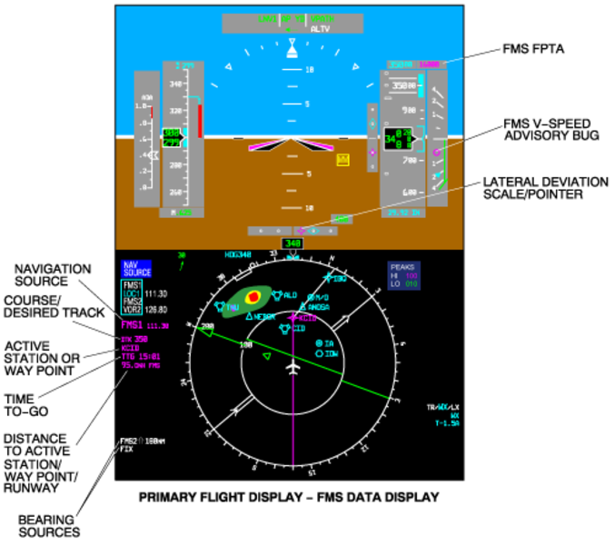
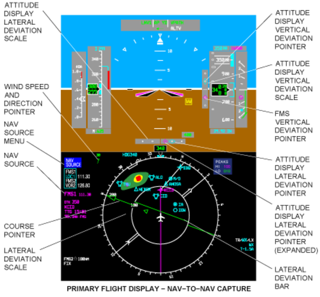
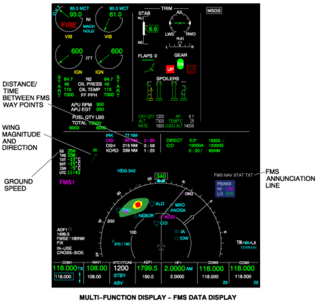
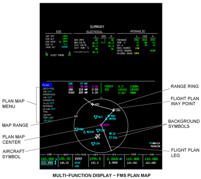
02/01/16
System Interface
The flight management system supplies its functions through internal interfaces between its components and external interfaces with other aircraft systems (IOCs, EFIS, RSS, and MDC).
Internal Interfaces
Pilot CDU/ Copilot CDU
The pilot and copilot CDU give control signals to each other with ARINC 429 high-speed (HS) data buses (L-CDU-3, R-CDU-3). These data buses determine the CDU that has control of the systems. The buses give frequency and navigation control signals to the systems.
CDU/FMC
The pilot or copilot CDU receives bus data input signals from the FMC (L-FMC-3, R-FMC-3). Then control signals return to the FMCs (L-CDU-1, R-CDU-1).
FMC/DBU
The FMC No. 1 and No. 2 control data flow to and from the DBU with ARINC 422 low-speed busses (L-FMC-5, R-FMC-5, DBU-1, DBU-2). These data busses control the input of navigation, performance and V-speeds data used by the FMS.
External Interfaces
FMC/IOC
FMC No. 1 and No. 2 control data flow to the IOCs (on L-FMC-1 and R-FMC-1 data busses) and from the IOCs (on L-IOC-4 and R-IOC-4 data busses).
FMC/EFIS
Control data goes to the EFIS from FMC No. 1 and FMC No. 2 on L-FMC-2/L-FMC-6 and R-FMC-2/R-FMC-6 data busses respectively.
CDU/IOC
The CDUs give/receive data to/from the IOCs with ARINC 429 HS data buses as follows:
- CDU No. 1 and No. 2 give frequency and navigation control data to the IOCs (on L-CDU-6 and R-CDU-6
- Each CDU receives GPS data from IOC No. 1 (on L-GPBUS-1) and from IOC No. 2 (on R-GPBUS-1). The IOCs get this data from the radio interface units (RIUs).
CDU/RSS
The pilot CDU and copilot CDU give frequency and navigation control data to the left and right radio-sensor systems (RSS No. 1 and RSS No. 2) with ARINC 429 HS data busses (on L-CDU-6 for RSS No. 1; on R-CDU-6 for RSS No. 2).
DBU/MDC
The MDC (in the IAPS card-cage (ICC)) sends fault history data to the DBU for download to a diskette/USB memory drive. Data is transmitted to and from the DBU with RS-422 data busses (MDC-6, DBU-3).

System Monitoring
Deviations in operating conditions and fault conditions (real and potential) are shown to the flight crew on the CDU, PFD, and/or MFD displays.
The CDU shows all the fail-condition messages related to the FMS. Some of the FMS messages are automatically shown on the PFD and/or MFD on the FMS annunciation lines.
On the top line, the amber messages have priority over the white messages. On the second line, the annunciations can be clearable (lower priority) or non-clearable (higher priority). Also, if there are more than one annunciation for the third line, the annunciation that has the highest priority shows.
02/02/16
System Test
The FMC includes self-test functions. After a short power loss (less than 2 minutes in duration), the FMC continues operation (warm start) at the situation that existed before power was lost. There are no observable effects, other than possible CDU blanking because of the power loss. The flight plan and all selections stay unchanged.
If the power loss stays more than 2 minutes, the FMC does a self-test. That includes RAM (random access memory) and ROM (read only memory) tests and battery level test. Before operation (cold start), copyright page can show. Subsequently, the CDU shows the STATUS page.
After long power interrupts, the changes that follow can occur:
- Scratchpad is cleared
- Active flight plan becomes a modified flight plan
- History points used for MFD PLN HISTORY screen are cleared
- Original flight plan used for MFD PLN PROGRESS and HISTORY screens are cleared
- If on ground:
- Sensor selections are reset to default selections
- NAV radio tune mode (AUTO/MAN) is set to MAN
- REF waypoint specified on FIX page is cleared
Also, the CDU monitors its own operation and the status of the buses connected to it. If the CDU finds fail conditions in these systems, the fail condition status is reported through a CDU diagnostic word.
11/10/20
Component Location Index
| Component Location Index | |||
|---|---|---|---|
| IDENT | DESCRIPTION | LOCATION | IPC REF |
| - | FLIGHT MANAGEMENT COMPUTER (FMC NO. 1) | ZONE(S) 222 | 34-61-01 |
| - | FLIGHT MANAGEMENT COMPUTER (FMC NO. 2) | ZONE(S) 222 | 34-61-01 |
| A69 | CONTROL DISPLAY UNIT (CDU) (RH) (STANDARD INSTALLATION WITH SINGLE CDU ON RH ONLY) |
ZONE(S) 212 | 34-61-05 |
| A69 | CONTROL DISPLAY UNIT (CDU) (LH) (INSTALLATION WITH DUAL CDU'S) |
ZONE(S) 211 | 34-61-05 |
| A68 | CONTROL DISPLAY UNIT (CDU) (RH) (INSTALLATION WITH DUAL CDU'S) |
ZONE(S) 212 | 34-61-05 |
| A191 | DATA LOADER | ZONE(S) 221 | 34-61-09 |